


Fuselage About midway through
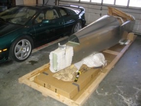
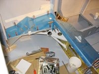
Parts. During the unpacking process. This was a lot of work to organize and inventory. There's lots and lots of stuff.
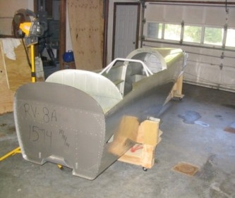
(7/23/05) Since there are no explicit plans for quickbuilders, you walk throught the normal slow build instructions, checking off things that are done. Van's logic is that this is a good way to learn the structure. He's probably right, but I would sure like some outline of a suggested sequence since you clearly do some things in a very different order for the QB versus the slow build.
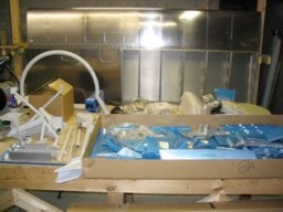
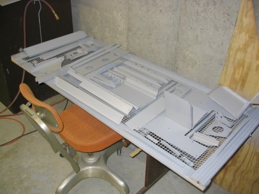
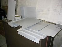
(8/28/05) I've been spending time preparing the smaller parts prior to assembly in the fuselage. They're starting to accumulate so it's almost time to break out the priming gear. This is about half of the stuff that's queued up, including repriming the baggage floor and removable bulkhead (I hate Van's wash primer).
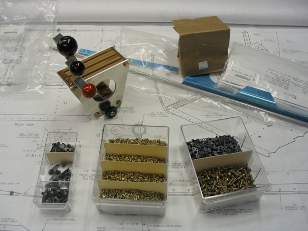
(8/28/05) I received an order from Van's yesterday which included a bunch of nutplates for the floor, and the throttle quadrant. I thought I had ordered the fancy one with the engraving and the larger throttle handle, but I kind of like the simplcity of this one. Also visible is the rear seat throttle lever kit. I want basic flight capability from the back seat.
The rivets are NAS 1097 type in various lengths. After scouring the incredible rich source of various people's web logs, it seems like these are the nads for nutplates, only requiring a very shallow countersink.
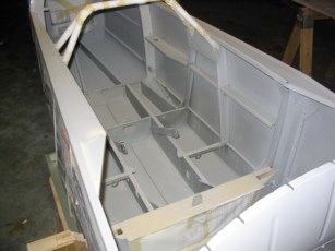
Next up is engineering the floor split. I will be cutting the floor and making most of it removable. Only the section under the flap actuator weldment will be permanently riveted down (after the step is installed, of course).
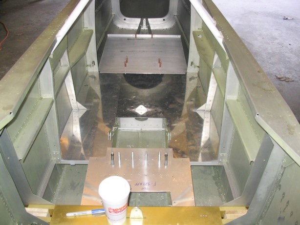
(9/11/05) Spent a few evenings last week trimming the floors. The floor panels have to be installed and removed quite a few times during the process of fitting. This has got me to thinking that perhaps removable floors may not be all that practical. With the stiffeners riveted on the forward portions of the F830 and F831 panels, I am not sure that the panels could be deformed enough to get them in and out without damaging something. They could probably be loosened, but getting them out will be tricky to say the least.
As with most things like this, I will spend some time scouring the web to see what others have done. Certainly many people have installed the nutplates and screws for the floor panels, but I have not seen many follow-ups on how much utility they REALLY serve.
There seems to be another camp that says why bother with all that work. If there is nothing active under there, just go pop rivets. If access is REALLY needed, drill out the rivets.
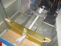
(11/09/05) Control Stick torque tube bolted in place. Tricky bugger to line up exactly and get drilled so that there is no side play on the bearings. You can really feel it when there is any binding at all. It will probably shift a bit when fully snugged up. I am sure that can be extra fine tuned by playing with the snugness of the bolts.
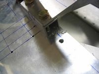
So there I am, finishing up the floor nutplate hole drilling late at night, and I grab the right angle drill since this hole is under the right side seat belt bracket. Forgetting that I had just changed bits (to 5/32, I think) a split second later I had drilled this one too much, much larger than my usual #17 or #18 for screw holes. This will warrant a call to Vans. It's probably OK, but it pays to be sure.
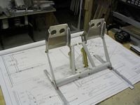
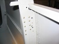
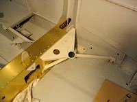
Note the many lines used as reference for making sure the control weldment bracket is straight on either side.
A lot of stuff has been going on that I didn't fully take pictures of. My son keeps leaving the camera batteries dead after taking pictures of himself and his friends (cheesy excuse). I fit the flap weldment and UMHW blocks, built up the front seat back, and the rear seat back. The upper seat fiberglass was trimmed. I am sure I'll trim this down more once the needed canopy handle clearance is measured. I also fitted the front baggage compartment pieces. A lot of work with no photos.
I called Van's to ask about the best type of screws for removable floors, stainless, or the AN815 type used in a lot of other places. Ken's response was, "The plans don't call for removable floors. Why would you go and do a thing like that?" I guess they stick pretty close to the party line about not endorsing modifications. In the end he did admit that it didn't really matter since any screw was likely to be stronger than the aluminum pop rivets called for in the plans.
I was initially very gung-ho about removable floors, but at this point I wonder about their true value. If I keep all the electronics and stuff in accessible areas I am seriously doubting that I'll spend the effort with the nutplates and such. Of course I only come to this point after buying all the nutplates and two different types of screws. If I scrub them out and prime well, there should be no corrosion problem in my lifetime that would cause me to need to remove them.
I still dislike the wash primer, so once the interior pieces are all fitted I will be cleaning and scrubbing down the interior with IPA and shooting primer in there as well, probably all the way back to the bulkhead behind the baggage compartment.
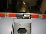
Being a EE I am a proponent of single point grounds, so a rear mounted battery will mean I run two cables forward for positive and negative. There is ultimately a weight penalty, but since it is rearward biased weight, it gives me flexibilty on the prop choice. If I were to use the heavier Hartzell it would not penalize the CG envelope as much.
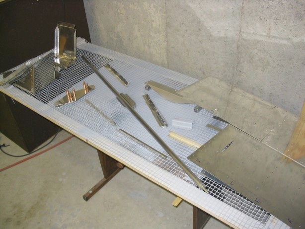
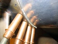
The left side console holds the throttle quadrant. This piece is the throttle/mixture/prop cable bracket. It's fashioned from a big honking chunk of angle. There's nothing like taking a big piece of rough stock and forming and shaping it until it comes out as a beautiful piece that is pleasing to the touch.
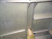
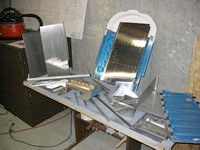
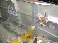
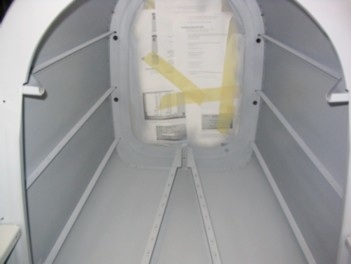
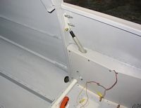
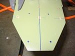
Before fitting the side consoles, the channel caps should be fit over the F804C formers. As you can see, these are quite wavy in their relaxed state. Any pressure or leaning on the side of the fuse exacerbates this. I make a point of never leaning on the side of the fuse, but here it is anyway.
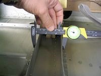
You can also see that they are way too close together to fit under the F804 channel cap, the interior span of which is 3 inches. The relaxed span of the F804C plates is about 2.8 inches. Persuasion with a seamer helped a very little, but not nearly enough to hold the caps while drilling.
Hey, FAA! That's my hand. I've got to remember to get some pictures of myself building this thing.
These are still a hair too wide now as they make the flanges of the channel cap bow out slightly. Just a hair more needs to come off.
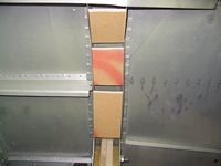
Even well into the project I am finding uses for bits of the shipping crate, which are still in a pile waiting for burning day.
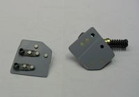
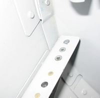
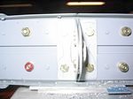
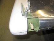
(12/03/05) I am making the rear baggage floor removable, which means the rear of the floor mounts, which share a fastener with the front of the baggage floor, will need nutplates. The outboard two holes do not have enough room for nutplates, so I had to fabricate these spacer plates to mount the nutplates. You'll see how these mount in the next photo.
I've settled on making the complete baggage area removable, including the floor, but riveting the cabin floors in place. That way I'll have complete access to the rear of the plane for inspection, and anything I mount under the baggage floor. I have convinced myself that I don't need to have the remainder of the floors removable.
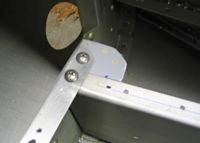
Sorry about the crappy picture. My camera chose to focus on the leaf that's visible through the step mounting hole. You can see the Nutplate thingy screwed in place. There is one rivet hole drilled toward the front of the thingy. I drilled another directly in between the screw holes. These are small rivets, but all they have to do is hold the plate in position until the screws are snug. The other side (right) looks the same only flipped 180 degrees.
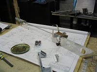
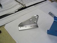
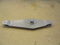
(12/28/05) Put everything together for front quadrant and rear throttle on the bench. I purchased the Van's quadrant and decided that the inboard mounting bracket could be replaced by the plate with the 3 holes (I forget the F# right now). It'll save maybe 3 ounces. 100 things like that and I'll have some impact.
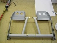
This is the co-pilot throttle mounting bracket. I fabricated spacers and riveted them to the front side of the plate so it would not require deforming the mounting bulkheads at all. This matches the actual thicknesses of the mounting parts. I'm not sure why this is not part of the plans for the assembly.
Adding those spacers gives you something to relieve to fit flush behind the bulkhead flutes, which otherwise would be squeezed flat when the throttle mounting plate is screwed in. More work, I know, but it seemed like obvious changes to make it right. The rear spacer is actually made of 2 .040 aluminum strip to exactly match the gap. The front has a single thickness.
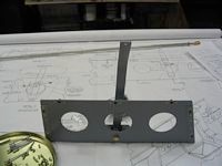
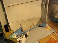
The whole mess mounted in the plane. Van's provides templates as starting points for the connecting pushrod holes. You use those to define a starting position for the holes on the bulkheads, then run a string between the rod attach points on the two levers and trim the holes so all sides are cleared by the radius of the rod plus a 16th for clearance at all positions of the levers. Since the levers move radially, the holes end up oblong.
The front quadrant got installed and removed maybe 6 times in total to get the fit right. Mine are probably slightly larger than they need to be by a 16th or so. Better safe than sorry. No binding allowed. This is critical.
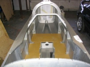
Wow. Is that fuse getting messy. I'm just about as far as I can go with fitting things before cleaning up, wiping up the wash primer and shooting the inside of the fuse. When you wipe up the wash primer with IPA, all the green color comes off pretty easily, but there is definitely a coating left on the metal. It is not ALL removed by the IPA. I am going to try the rear baggage compartment panels first with a wipe down, then priming with Marhyde.
I've read where folks complain about Marhyde not being very durable and scratching easily, but I have found that if you clean the surface well, scothbrite it, and alodine (unless it previously had Van's wash primer applied, then just clean well with IPA) it seems to hold up well. It is very, very important to let it cure fully though. I have had it display easy scratching and chipping if working with primed parts with less than week to let the stuff fully "cure". Your mileage may vary.
Since I actually like the color of the grey Marhyde primer, I may chose to have that be the final interior color. Doesn't get much lighter or easier to repair than that. I'll see how I like it after the whole interior is primed.
Bench assemble the rudder pedal assembly. The pedals themselves are nice welded aluminum pieces by Van's. The edges are a bit rough, and take quite a bit of cleanup to look finished. The weld quality is outstanding, having firsthand experience messing up aluminum welding in the past. Took some sanding of the welded rudder pedal axle tubes and pedal brackets to get them buttery smooth in operation.
I was missing my 2 sheets of UHMW plastic from which you are to make bearing plates for the outsides of the rubber pedal brackets. Called Van's and was expecting to have to pay for this stuff since I am well outside the 30-day inventory shortage replacement window. They were totally fair and tossed the parts in for free if I paid the postage. Granted that these are only $1.50 part (2), but they could have been weiners about it and they weren't.
I may grouse and complain about nitpicky things from time to time regarding Van's plans or terse instructions or delivery time for parts, but all-in-all they are an outstanding company that shoots square and fair and we builders should all be incredibly thankful that a company of this integrity exists for us. The experimental aircraft business is filled with dreamers, schemers, and fly-by-night operators. Van's is not one of them.
I called Van's and suggested that I simply relieve ALL the rivet head clearances into the angle and add another LP4-4 in front of the rivet that was to be drilled out. Scott said they've looked at this a lot since it is a fairly common question regarding the alignment issue. He said my plan should work out OK and was an acceptable modification.
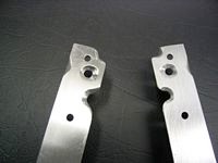
These are the front of the rudder base mounting angles with reliefs cut out for the existing rivet heads and my "extra" hole in front of them. I still have a touch of polish and cleanup to do. With all that metal hogged out for the rivet head clearances, the strength of the angle in front is probably very compromised, but I can't imaging that it is under much stress at all. From my perspective the angle could be an inch or so shorter and skip the whole interference issue altogether.
In looking at it, the angle experiences a small downward force from the weight of the pedal assembly, then some amount of fore and aft shear force from the pivot of the rudder pedal axle. There are 13 other rivets that can assume this shear force. My only guess as to the front rivet is included is to tie the rudder support angle into the crossmember at the base of the firewall.
(1/8/06) Well, I finally got to the point where there was almost nothing else I could do without priming the interior and the huge stack of parts that has built up waiting for priming. I made sure every hole in the fuse was deburred and cleaned it out, vacuumed well, and started the endless wipedown of the interior wash primer. It took the better part of a day to wipe off the green wash primer. IPA in a squirt bottle was the main tool. A squirt, wait a second for the primer to soften, then wipe it off with a clean rag. The anodized spar, firewall, and powder coated parts were then masked off.
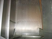
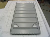
After the first interior coat. I used the touch up gun with Marhyde and it seems to have worked out OK. Two light coats gave pretty good coverage. The color is good. The finish quality is OK. I have no preconceptions that this is going to be a show winner, but light and servicable is the name of the game.
Two light coats seemed to cover well. The camera flash always seems more critical than what can be seen with the naked eye.
The baggage area was done with Marhyde in rattle cans up to the bulkhead behind the baggage area. Rattle cans were just easier than using the gun with the hose in a small enclosed area. The overspray with the gun gets intense. Further aft will remain Van's wash primer.
(1/15/06) I used the long weekend to prime all the parts that had built up. Batch after batch after batch. I will not let the pile build up that large again. There are even more stacked elsewhere (on all that exercise equipment that never seems to get used any more). I think it's time for new cartridges in my respirator after this weekend.
(1/16/06) It's been so long since I've riveted anything permanently, I thought I would start with something easy. This is the elevator bellcrank. Cake. It feels good to put stuff together that I know is not coming apart again.
It really hits you just how light aluminum construction is when the clecos are out and the part is complete. This seat back is strong and weighs about nothing.
I also had to sand the inside of the tubes and grind off a hair on the inside faces of the big clevis pin tubes (adjacent to the nuts) to allow the nut to bottom on the threads enough to fit the cotter pins. The non-sliding tube interiors were primed, and the bearing surfaces all got cleaned and a good coat of lithium grease before going together. A lot of little things to get this assembly together.
(4/17/06) The nutplates for the flap block bolts gave me some trouble. There was no way I could get a gun in there and none of my squeezers fit. I ended up using pop rivets to affix the plate then carefully filing off the top so they were perfectly flush. According to Mike draper a "no-hole" yoke on the squeezer would have worked, but I don't have one of those and didn't want to wait.
(4/20/06) Once the nutplates were on, it was an easy matter to get in the floors, and UMHW blocks and mount up the flap motor. It took a little grinding of the armrest to get the flap arm to run interference-free. It's pretty cool to wire it up and run the motor up and down and actually see the first powered piece of the fuse run.
(4/30/06) I riveted a .040 stiffener to the back side of the bulkhead just for some peace of mind. I was working out there and thinking about the air loads of the flaps all concentrated on that relatively thin bulhead piece. This should distribute the loads a little bit. Some folks tie into the skin by using an angle instead of a plate. I didn't feel like making more holes in the skin in this area.
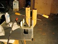
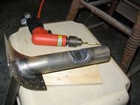
(5/5/06) Here is a truly Rube Goldberg setup for clamping the tail tie down block while drilling. Hey, whatever works. I was tackling little odds and ends in the fuse this day and this was a little diversion from the interior. Check out the funky drill arangement I hacked together to get those buried holes. That silver piece is a screwdriver extension. I tapped the receiver for a set screw and filed a flat on the 90 degree drill and it works. It wobbles a bit, through, so I would only use it slowly and for pilot holes. You really need a third hand to run it, though.
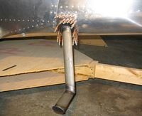
You have to get the flat part flush, but also make sure the angle of the support tube inside the plane is not at too severe an angle such that the support block can still be mounted on the interior rib. A lot of fiddling and diddling. I still see no way to avoid interference with the rudder cable.
Despite my best tweaking efforts I still ended up with a shim. Had I pushed the bottom part in more, the interior tube angle would have been too high. Also, the step itself would have been on a slightly downward angle. I am sensitive to this now, and when I look at other folks steps, I can see that it is actually at a somewhat too steep an angle, so they probably didn't agonize over this as much. The fit is actually better that this camera angle leads you to believe.
I took the tube over to Harvard Machine shop, a small local outfit, and explained what I wanted. My only specification were some Sharpie lines drawn on the tube and a verbal description of the solution. The owner is an ex-plane owner and understood exactly. A couple of hours later he acually showed up at my house to deliver the part. He was curious about the plane and wanted to look for himself, so I gave him a tour.
His professional interest led him to the welded parts and he commented that the weld qualities on Van's parts are about as good as he has seen. He was also pretty impressed by the matched hole process whereby both ribs and skins are prepunched and actually line up. Kudos to Van's. Thank you Harvard Machine.
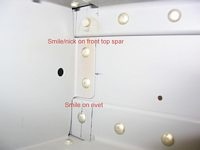
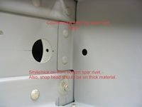
(6/20/06) Oh those F***ing weldments! After opening up the LG holes in the fuse, you first see how things fit. In my case, and on both sides of the fuse, the forward skinny tubes had to be bent inward slightly as they were keeping them from resting flat on the spar. and lining up with the holes. This is not easy to do as this is a pretty strong assembly.
In one of my few calls to Van's to see what they recommend, they suggested some sort of medieval process involving strong trees, a truck winch and a lot of force. The comment was that these were strong enough to land on, so a little bending tweak, unless you kink the tube, is not going to hurt them. My goal was to tweak the fit so that I did not have to file the holes much to get them to fit.
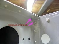
I did my bending with a heavy vice, some steel rods for leverage and some giant clamps. My son was apalled at how primitive looking a process it was. A lot of sweating and grunting involved. I still ended up doing a little filing on both sides, but not much. I did not run bolts through the spar holes yet, so we'll have to see how this works out on final assembly. Though there are only a couple of pictures here these weldments took hours and hours of installing, tweaking, removing filing, fitting, etc...
After the weldments are fitted, the consoles go together pretty quicky. It almost seems like child's play after working with the steel bits to be working with aluminum again. The edge distance for the screws on the fuse side was very tight on this side with the Van's piece, and I didn't have any gauges that I was going to put there, so I just made a flat piece out of some 0.032 and fit it myself.
(7/6/06) The right side console also goes together pretty fast once the weldments are in. I did use Van's piece here since I think I will place the CO monitor and the Hobb's meter on the instrument panel space down there.
(7/7/06) Seat Ramp going in. Nothing big here. Very straightforward.
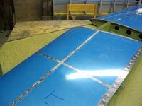
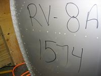
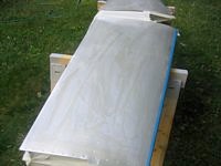
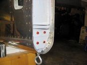
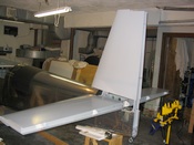
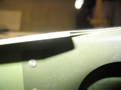
(7/9/06) Surprise time!! It's time to start the horizontal stab mount, so I went to retrieve it from the storage location in the basement. It was in a corner on some blankets, flat on the floor with various other light parts stacked up on top of it. Periodically I would check it to make sure there were no nesting mice, but I never turned it over. Holy Crap! When I did, there were these big corrosion blotches on the bottom. Close up view here.
It only got worse when I peeled back the vinyl. This is a snakey white powder-like substance that doesn't just rub off. It's in there. Just on this side and just along the spar on both sides. The only thing I can think of is that something must have leached up through the blanket from the floor and reacted with the aluminum. I have other parts on the floor over there, resting on SYNTHETIC blankets that are just fine.
What to do now? Is it trashed? Well, I am first going to try to remove the corrosion and see what it looks like cleaned up. Is the structure OK?
After a couple of hours of scotchbriting and alumaprepping, then alodyning, this is the result. Alumiprep did the best, first attacking the oxide before the aluminum, so it took most of the debris off the surface. I still had to wet sand with 150 and 220 grit with alumiprep as the liquid medium to really get it off. I probably thinned the metal a bit on one side and shaved down the rivet heads a little.
Though the surface looks OK, there is no way that every bit could be accessed in the edges around the rivet holes. Over time there may be some return around the rivets. I am looking now at the options:
-
•Options:
-
•Prime and mount: Keep monitoring it over time (yuck)!
-
•Replace the skins: Ouch. A lot of work.
-
•Build a new one: Clear conscience, much more work.
-
•Use my old HS: I actually have my HS from the first build attempt. I could use that one, but it's been so long I would have to go over it with a fine toothed comb.
I looked a little at what it would take to mount a brand new stab later. The problem is the mounting holes at the front of the stab. I am sure that the rear holes could be matched drilled at the HS811 bulkhead bars, but the front ones would be a trick. I may have to consult with Van's on this one.
(7/15/06) I consulted Van's this week. Their advice was kinda wishy-washy. Should be OK, might not if I thinned the sheets too much. Van's did confirm that it is indeed possible to match a new HSTAB to an existing set of mounting holes. Not easy, by any means, but possible. Match dilling the front angle holes is the trick. You have to come up from the bottom and that's the trick.
I also tossed the problem up to the Yahoo RV-8 group. Great group. The advice here was also all over the map, though I did learn some things. 10% compromise to the thickness of a panel is generally considered a failure. For the 0.032 sheet of the HSTAB I would have to have sanded off 2-3 mils before this would be a REAL problem. I don't think either the corrosion, or my sanding actually got that deep.
Though there is no real way to measure the actual thickness without drilling holes or cutting out test coupons, neither of which I am doing. I used the presence of the little dimples in the rivet heads for reference. They really don't look any shallower than the untouched ones, so I believe that I really didn't take off too much aluminum.
I also looked closely at my old HSTAB. Interestingly enough it was totally corrosion-free after sitting on a shelf for 5-6 years with the vinyl on. As mentioned before, it was my first instance of metal construction, and there were things I didn't like. Probably not a problem, but below my current standards.
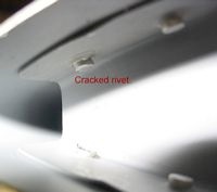
These are some of the rivet flaws I noticed on my old stab. They don't pass muster today. The cracked rivet in the tip rib is not good. I also used a countersunk rivet on one of the ribs on the front spar. I have no idea why I did this. I suspect that I boogered up a rivet then boogered up the hole on one side and countersunk to clean up all that boogering. Makes me wonder what else I did inside the stab. All that said, I do not plan to use this part. I would rather buld a new stab from scatch than use this one.
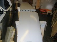

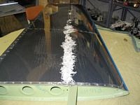
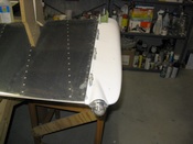
(7/15/06) Back to work. After discarding the idea of using the old horizontal stab, and convincing myself that the new one was OK to use, with the fallback being that I might later have to rework it for corrosion problems with a new skin/stab, I got to work prepping it. It's been etched, alodyned, and primed. As shown, there is little or no evidence of the corrosion and the primer has sealed the rivet heads. It was a heavier coat than I would normally have used, but this is a special case.
I used my central pneumatic HVLP gun for the first time (part number 43430). Wow! HVLP is the way to go. Gone is the enormous cloud of overspray I would get with my little touch-up gun. It is also hugely more paint efficient as a result. I consumed much, much less primer in the process. Much of the paint with a traditional gun must be lost to overspray. The result, as you can see, are not too bad, either.
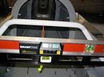
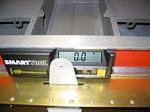
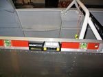
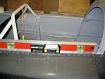
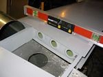
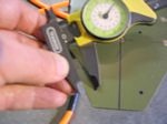
(7/23/06) With the fuselage leveled at the top longerons, spar box, and front-to back, it really looks like there is a slight twist to the fuselage. Everything is zeroed, as shown, until you get to the HS mount platform. That's 1/2 a degree low on the left side, which tranlates into almost half an inch low on the left, and half an inch high on the right at the HS tips. In order to correct for this it looks like I'll need almost an 0.040 shim on the left, which seems like quite a lot, or to shave the right 0.020 and add an 0.020 to the left. Again, something I will confirm with Van's before comitting drill to aluminum in this critical operation.
I called Mike Draper, who is a little ahead of me, and has a QB fuse received about the same time as mine, and confirmed that he, too had the same issue, but only required a single 0.20 shim to correct. Apparently Van's jigs in the Phillipines must be off a hair.
Did I mention that this is the coolest level in the world! This would have been painstaking to try to judge with a bubble level, especially with my aging eyes.
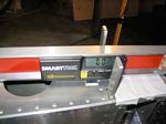
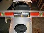
(8/05/06) After fiddling and diddling with the alignment the HS is mounted. In the horizontal I read 0.1 degrees off, but if I just rest my finger on the level, it zeroes, so it's right on the edge. Well within tolerances, certainly. I did not yet drill the interior two bolt holes on the front mount angle. I'll have to crawl inside and come up from the bottom to get those. The outsides are done and well aligned.
Once it all looked good, I reached in and marked the hole location for the lower bolts. Those holes had been pre-drilled in the tie-down bracket per the plans, and I had previously riveted the bracket to the rear bulkhead. I had then drilled the pilot holes through the bulkhead for the VS bolts.
When I pulled it apart to check the hole locations, I found that they were very low and violated edge distance to the edge of the rear VS spar. After staring at it for a while, I determined that I must have mounted the tie-down bracket too low. The only hard dimension given for this is relative to the lower edge of the VS rear SPAR. In hindsight I should have first test mounted the VS and used the VS spar to indicate where to mount the tie-down bracket. When I mounted it I placed it flush with the lower skin, based on what it "looked" like in the plans. Clearly this was wrong. Unfortunatley, as with so many mistakes in building, the clarity is only apparent in hindsight.
I can see how I made this mistake since the detail in the plans and the instructions don't generally include sequencing information. The lesson is to think more through the sequencing and implications of the steps. The easy way to deal with this is to lower the VS until proper edge distance is achieved. This approach transfers to potential issues of clearance at the fronts of the VS and front spar clearance issues.
The harder thing to do would be to drill out the tie-down bracket and make a new one with offset holes. The hardest thing to do would be to replace the entire rear bulkhead since my new offset holes would certainly be very, very close to my already drilled pilot holes and clearly a volation of hole to hole distance. I've posted my quandry to the Yahoo groups and will probably also call Van's on Monday.
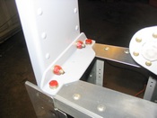
(9/16/06) After fiddling around with the alignment and mounting, I drilled the holes. That's my second vstab angle. The first was a little small. Red headed bolts are temporary bolts not to be used for final assembly. The nuts are drilled out so there are not locking. This thing looks like an airplane!
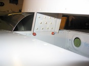
I decided to now work my way forward, starting with the rudder and elevators, then fit the appropriate stuff into the fuselage as I work toward the engine. I found a mistake made when I built up my rudder. You have to look close, but I put the fairing mount strips between the skin and the rib, instead of inside the rib. Duh! This was easy to drill out and place correctly, and boy did it help the fairing fit properly. Just that tiny change made all the difference and was a much better fit on the skin. Less chance of cracking.
Playing with fiberglass is very unlike aluminum. There is a lot of fitting and trimming to get it to sit right. I purchased some small, single-legged #6 nutplates and fit them inside the light cutout to secure it in place. It really looks nice when fit together.
The front cut is not as pretty as I'd like. I'll go back to this during the final finishing and probably tighten up that gap between the fairing and the rudder horn angle. A drain hole, sime filler, and I'll be done - for now.
Stephen D. Metzger Lunenburg, MA © 2011