


Panel & Electrical
Last updated 02/05/11
I used to have a whole mess of panel ideas presented. It’s far from settled on, though, as RV work has largely been at a standstill for a few years now. I made the mistake that everyone advises against in that I purchased a number of instruments WAY before needing them, and have rethought every single one by now. Some may get hijacked for use in the Helicycle.
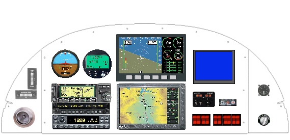
I have actually purchased a number of the elements of the panel, so there's no turning back now. I had 8 different variations in flight and this came out of top. Basic IFR, redundancy, cost, and utility were the main driving factors.
-
•Main Components:
-
•Dynon FlightDEK-180: AI/HDG/ASI/VS/ALT/Engine all-in one!-Purchased
-
•AvMAP EXP-IV: Incredible display. Blows away Garmin 396 by far!
-
•Pictorial Pilot: Autopilot and backup Turn Coordinator Purchased
-
•RMI MicroEncoder: AS/VS/ASI. Backup air instrumentation Purchased & built
-
•Garmin GNC300XL: IFR GOS & COM1
-
•Garmin SL30: COM2 & NAV
-
•Blue Screen: CDI & Other
The blue screen is an LCD display of my own design. It will display the GPS course deviation indications and message annunciations needed for IFR flight, as well as the CDI, lateral and vertical, for the SL30. I am an EE, so this will be a home brew project.
I am also constructing my own audio mixer functions. I just can't justify spending a kilobuck for that simple a function. I'll publish the design as I get closer.
My dad is currently testing the RST Engineering Marker Beacon receiver that I built. It went together pretty easily, but the alignment operation is a bit of a trick. He is an old radio guy, so this will put those skills to use.
(March 06) When the shop was cold this winter, I took the time to build up first my RST Engineering Marker beacon receiver. That went together quickly and my dad currently has it to test out. Next up was my RMI MicroEncoder. This displays Altitude, Airspeed, Vertical Speed, and some other stuff. I am planning a primary/backup electrical bus system. The Microencoder along with the Pictorial pilot and SL30 will be on the backup electrical bus for flight data when the main goes down. That coupled with the battery backup in the FlightDEK-180 should give ample flight data when there are electrical problems.
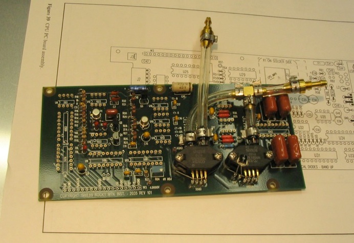
(3/10/06) The RMI documentation and kit packaging is the best I have ever encountered. The component strips have each resistor and cap laid out in the order that you use them in the instructions - amazing! A far cry from the RST Engineering MBR I put together which basically had everything loose with sketchy instructions. The PCB is good quality, and the phone support is first rate. The only deficiency in the product is that the design is a little dated. With modern components, this whole thing could probably be done with 1/4 of the components in 1/4 of the size. All in all, though it was an enjoyable diversion.
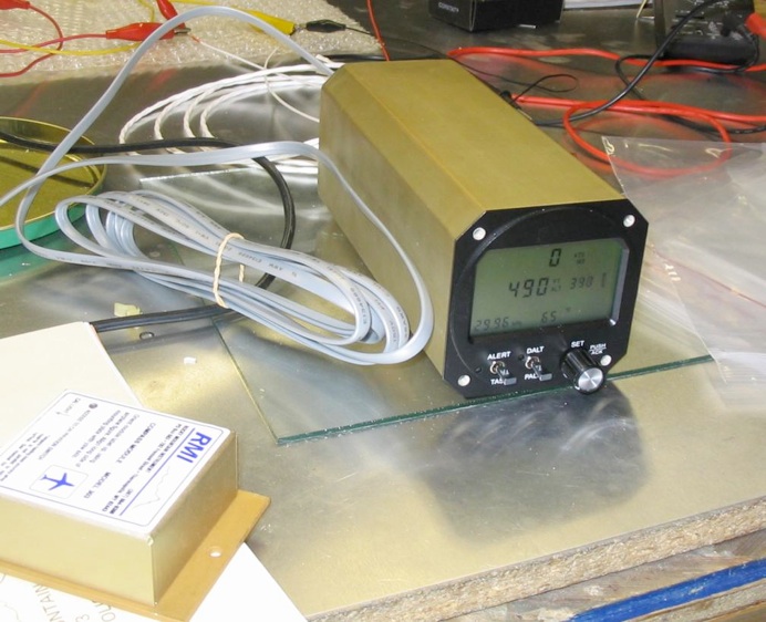
(3/15/06) The RMI powered up and lit. This is the second iteration. The first time I got nothing. I pulled it apart, touched up all the solder joints and reseated all the components and then it powered up. I think I will log a hundred hours or so before trusting this as my IFR backup, though. I built a differential column water manometer and the ASI does register, though I don't know if it is calibrated. I did opt for the compass option, so I have a backup for heading to the Dynon.
By the way, the altimeter setting is correct, and my house is really at 495 feet of altitude and the heading seems relatively correct, even in the basement, so those functions seem OK. Don't know about the airspeed yet, though.
(7/22/05) For something different, I took apart the Hobbs meter I bought at SNF to see about resetting it to zero. It was tagged as being out of a 1972 152 and had about 2300 hours showing. These are actually pretty neat little devices. Initially I hoped for the slimy method of reversing the polarity and hoping for a magic reset - no such luck!
Once you figure out the tricks, they come apart pretty easily. Unfortunately I found no easy way to remove the faceplate without bending it up. It'll take some cleanup to straighten it up on reassembly.
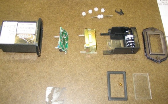
The interior assembly slides out the front as a unit. The springs on the back circuit (a simple 555 timer) contact the lug rivets at the rear of the unit. That circuit cards snaps out of the plastic carrier.
Next there is a solenoid. Two little tangs on the side of the unit are pressed and release it to slide out the rear as well. The springs on the relay make contact with two solder pads on the circuit card. No wires.
The gearshaft slides out one of the sides. The key to the mechanism is the little pawl in the upper right. The solenoid kicks the pawl, which advances the least significant reel forward a notch, then there is a fairly standard odometer-like gear train.
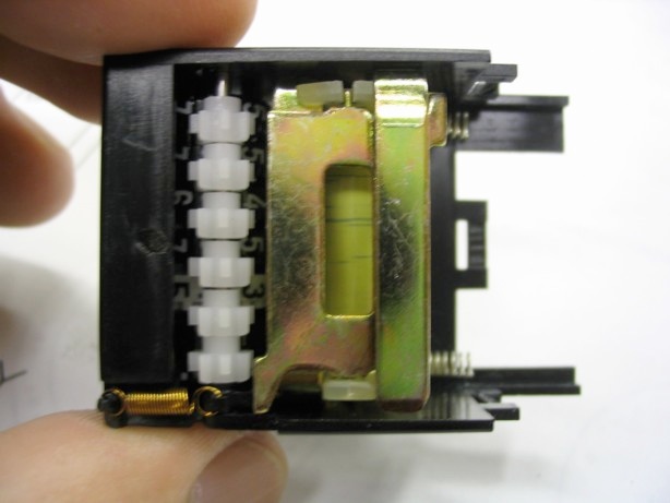
(7/23/05) With the gears out the indicator wheels spin freely. Line up the numbers, tape the indicator wheels in place while the gears are being installed, then remove the tape. Next, slide in the solenoid, and reinstall that little copper spring. Last (not shown), snap the circuit card back on behind the solenoid. I set it to 9989 and ran it for 11 hours just to make sure it was OK - it was.
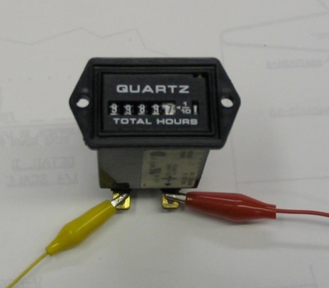
Ran for 11 hours and flipped over to 0000.0. Cool. $12 from the salvage bin at Sun-n-Fun. About an hour and a half to get it reset and working. Now I'll paint the faceplate after it's cleaned up and assembled. Arguably it wasn't worth the effort seeing as they are only $26 new from Aircraft Spruce. Oh well. This is a hobby. That's right, keep saying it - This is a hobby.
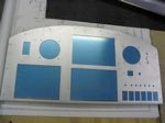
I contacted one of the suppliers we use at work (S&H Engineering) for mechanical prototyping about access to a water jet cutter. They were most accommodating and took the project to heart. I generated a detailed CAD drawing in VISIO for my instrument cutouts and within a week or two they had delivered me a pre-cut panel. I started with the RV-8 panel drawings from the Van's web site and added multiple layers for cutouts. Email me if you'd like the source. A side benefit is that they indicated that it would be easiest to start with a flat sheet, make the cutouts, then make the lower bend afterwards. The net effect is that I still have the untouched original panel blank.
Of course, after I got it back, I have found a number of errors, including the 3-1/8 inch instrument holes having the wrong screw spacing, so I will probably use this one for prototyping and then have a final one made later. Next time I will go to 0.090, as the 0.063 seems quite flimsy once the big cutouts are made.
Stephen D. Metzger Lunenburg, MA © 2011