
G0704 CNC Conversion
Having had some success with my beefed-up Shapeoko2, I recognized its limitations right away. First was strength. It is constructed of aluminum and fairly thin plate steel. The geometry of the gantry is such that if you grab the router and shake it up and down, there is a very noticeable amount of flexing.
Second, the Shapeoko being belt driven, there is always some amount of belt stretch. For engraving or wood that’s fine, but for cutting metal it just wasn’t going to be able to handle tough jobs. Just grabbing the end of the router and pulling, you can get maybe 20 mils of play from stretching without that much pressure.
Second, the Shapeoko being belt driven, there is always some amount of belt stretch. For engraving or wood that’s fine, but for cutting metal it just wasn’t going to be able to handle tough jobs. Just grabbing the end of the router and pulling, you can get maybe 20 mils of play from stretching without that much pressure.
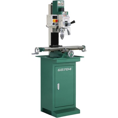
So, after a fair amount of web searching I arrived on a G0704 as a decent compromise. It is heavy enough for aluminum work (90% of what I anticipate cutting), maybe some light steel, not too expensive, and a LOT of folks have detailed their own CNC conversions on the web.
- Aluminum Cutting
- 0.001” accuracy
- Little “invention” needed for conversion
- Under $5K total investment (machine, conversion, SW, tooling)
This should be fine for my needs/wants. There are a lot of guys on the web who will say “Buy an old Bridgeport”. Who has the room or wants to make a second career of refurbing a giant old machine? This will do.
Maybe someday a Tormach PCNC1100. Maybe.
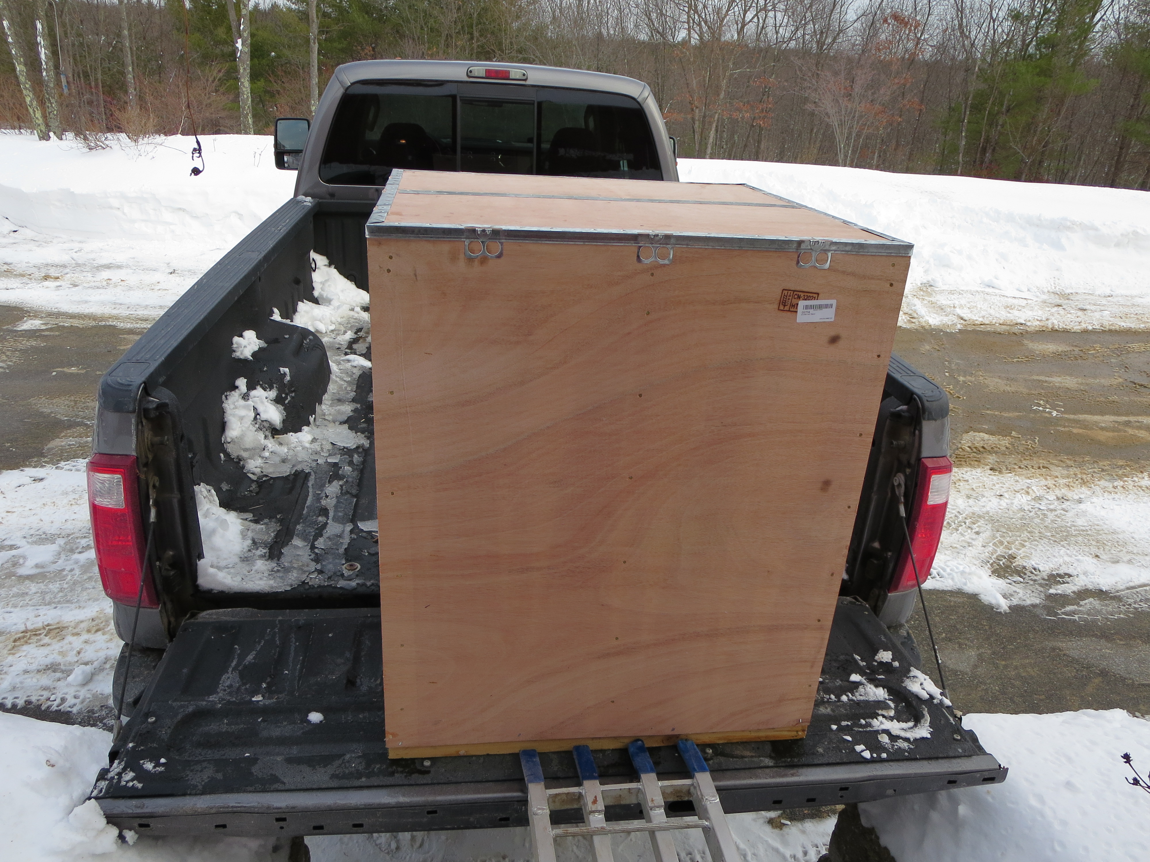
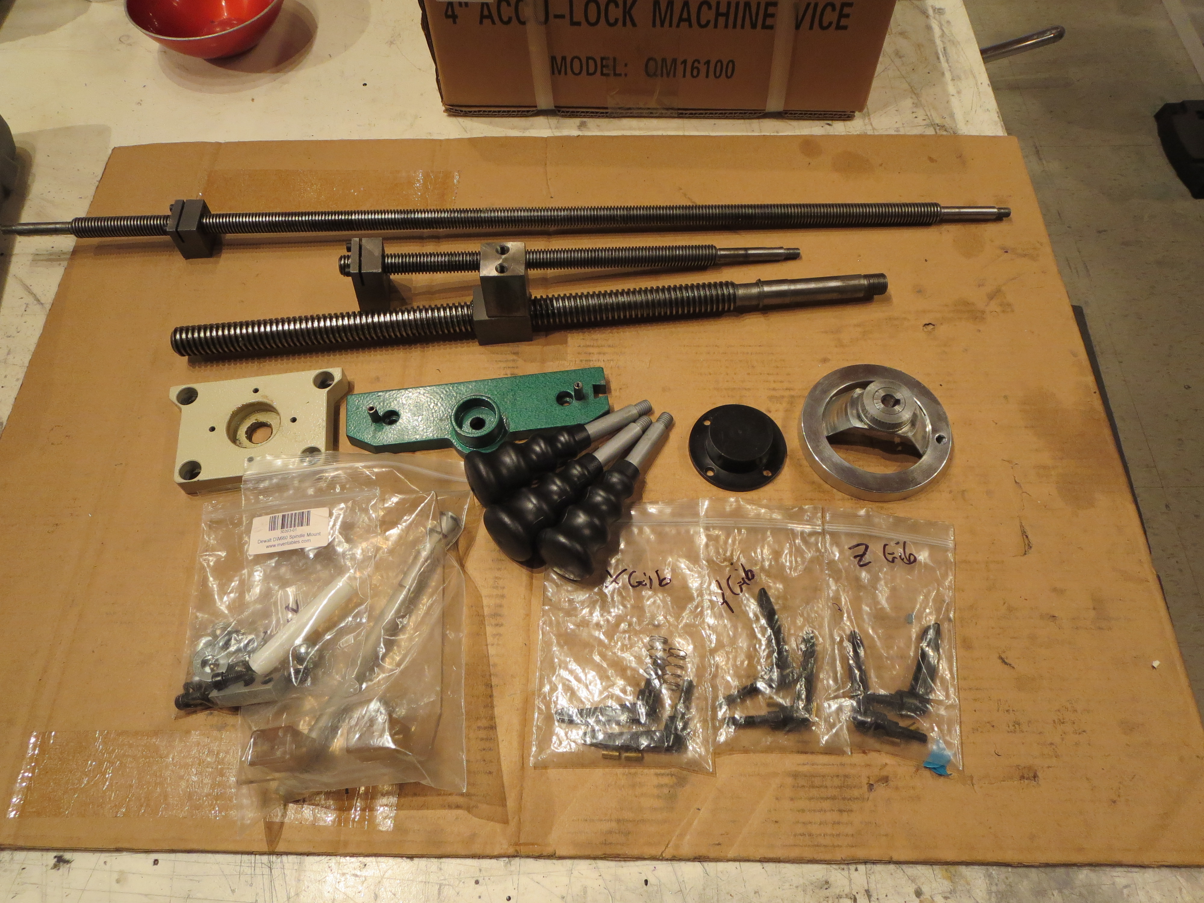
After Christmas I procured all the elements needed for the mill and conversion. I relied heavily on Automation Technologies for the lead screw kit, motors, and electronics. By getting everything all in one shot I wanted the conversion to go as quickly as possible. Some folks seem to make a hobby of the mill conversion process. I want to make parts for my helicopter.
Grizzly and Automation Technologies were outstanding. From order to delivery was just over a week for the mill and under a week for everything else.
- G0704 - From Grizzly Industrial (link)
- Conversion parts Kit - from Automation Technologies (link)
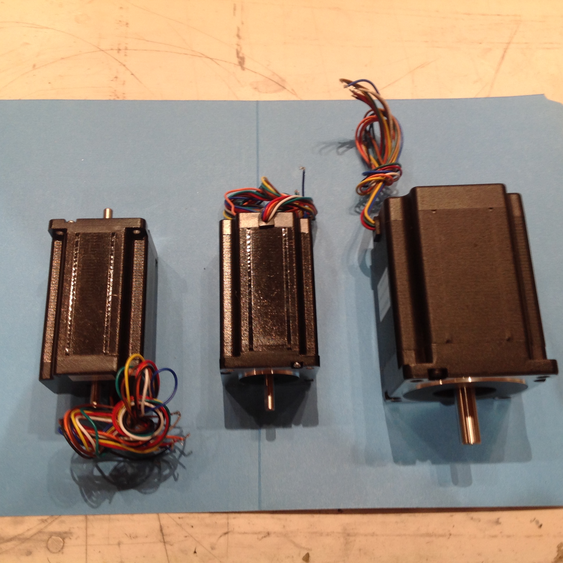
- Motors and Drivers - from Automation Technologies (link)
- Ethernet Smooth stepper from Automation Technologies (link)
- Mach3 Control software from Artsoft (link)
- Control Pendant - from eBay (this one did take 6 weeks in shipping)
- Tooling - from combination of Grizzly and Little Machine Shop.
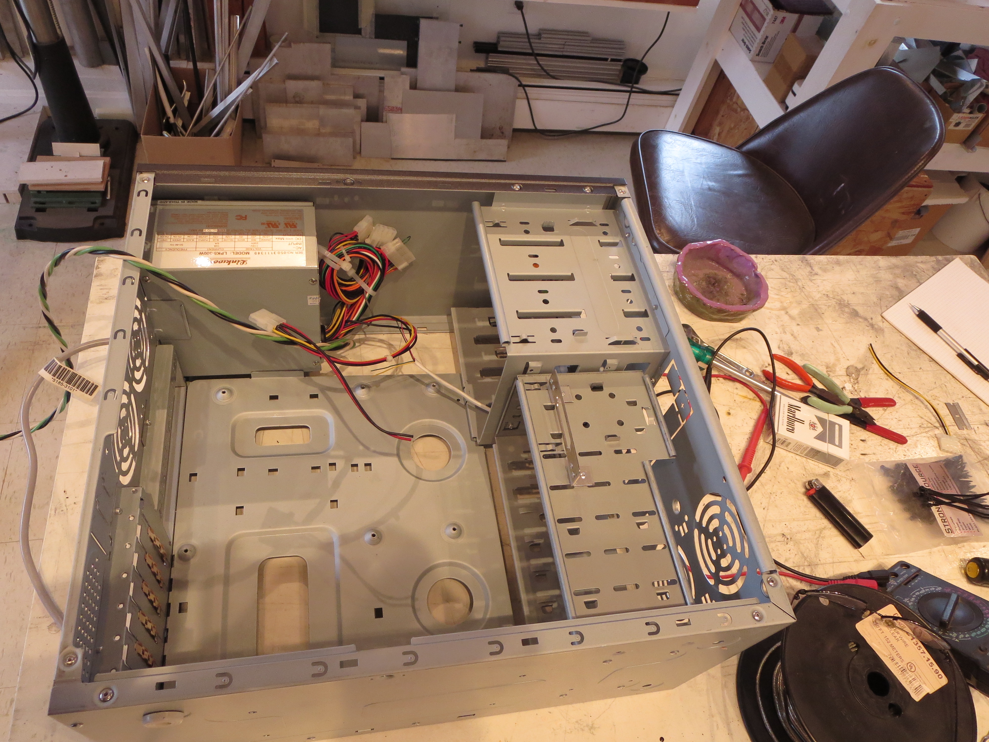
I already have a reasonably decent old PC to control the whole thing. Mach3 will be run on that machine. Commands to the machine are sent over my shop ethernet to the electronic box, which contains the power supply, Ethernet smooth stepper, and drivers. Since my shop ethernet is behind a router, there should be no other traffic on that segment. Reliability and isolation should be fine. Local control of the mill will be with the handheld control pendant for manual milling.
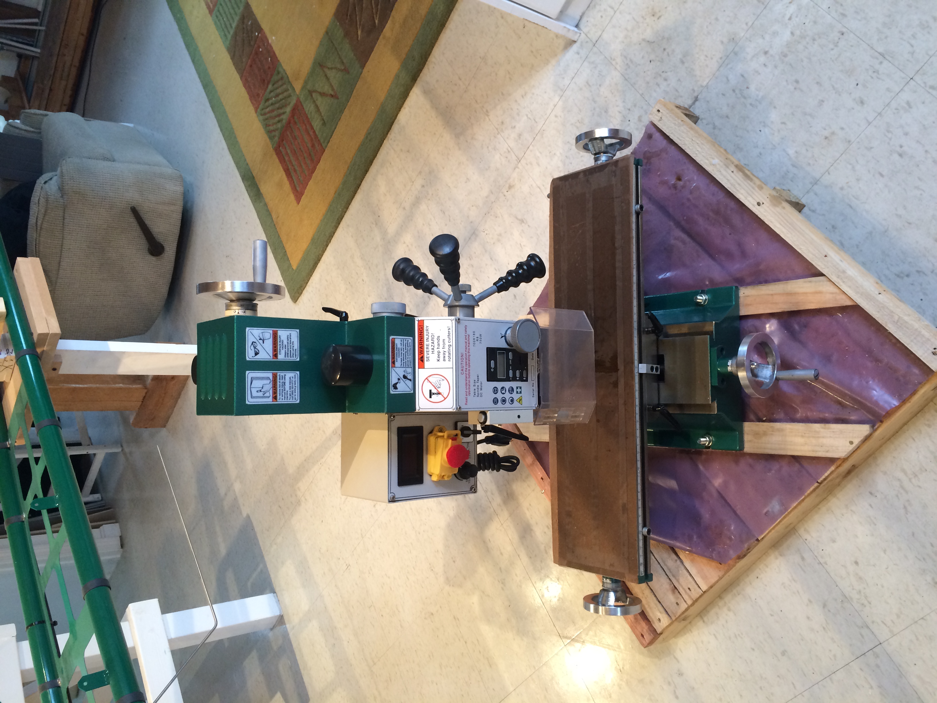
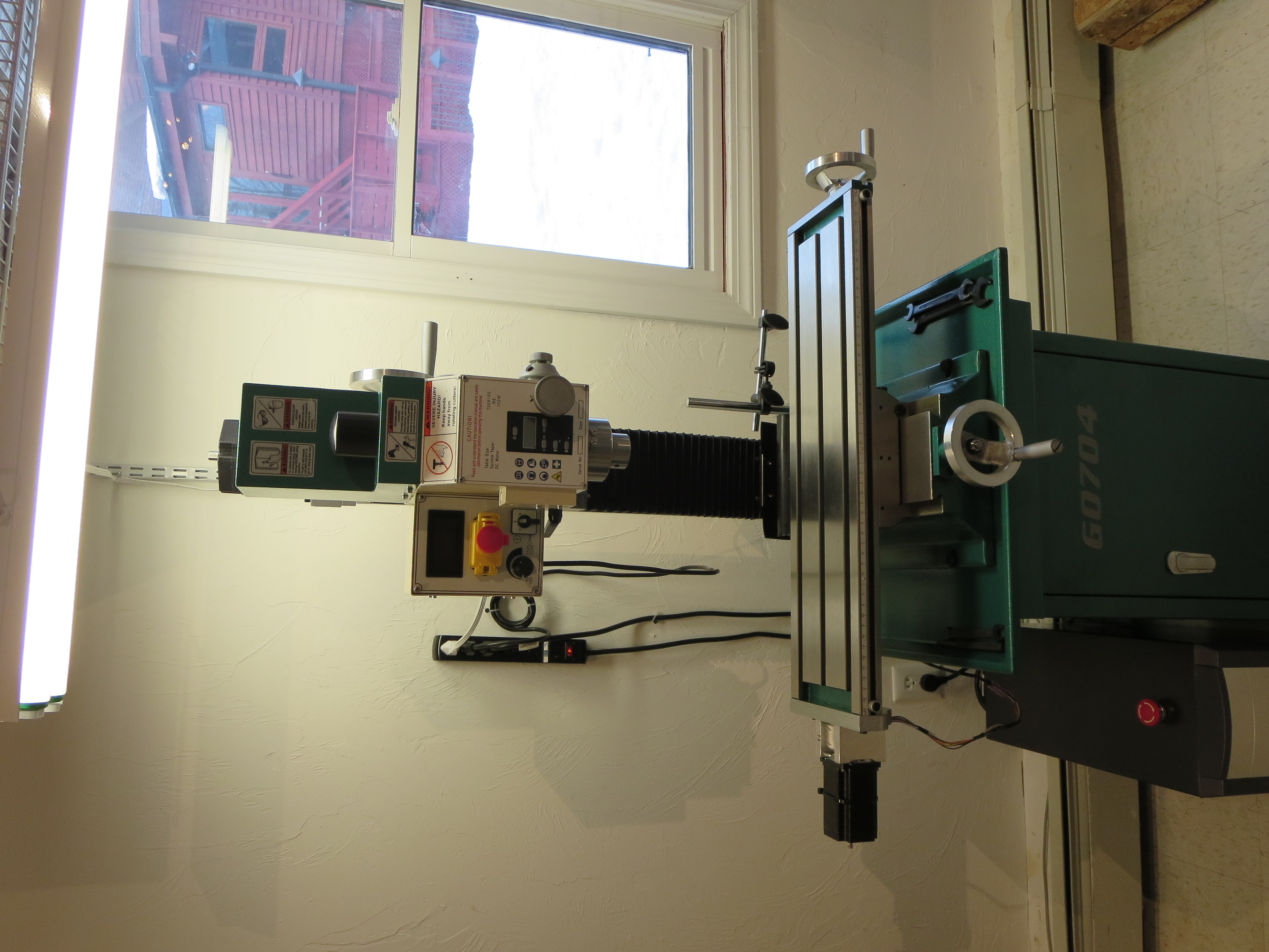
It did seem a little weird to never so much as plug the thing or turn the handles, but to straight away tear it completely apart down to the component bits. The head was removed intact, and of course the safety shield interlock bypassed. Like all Chinese machine tools it arrived covered in that waxy thick shipping grease which takes much WD40 and wiping to remove. It’s everywhere.
All the lead screws will be replaced with ballscrews and ballnuts. The left crank handle will be removed and the X-axis stepper mounted there, the Y-axis stepper will be mounted to the rear, and the Z-axis stepper to the top of the column. Should I wish to use the mill manually I will still be able to do so.
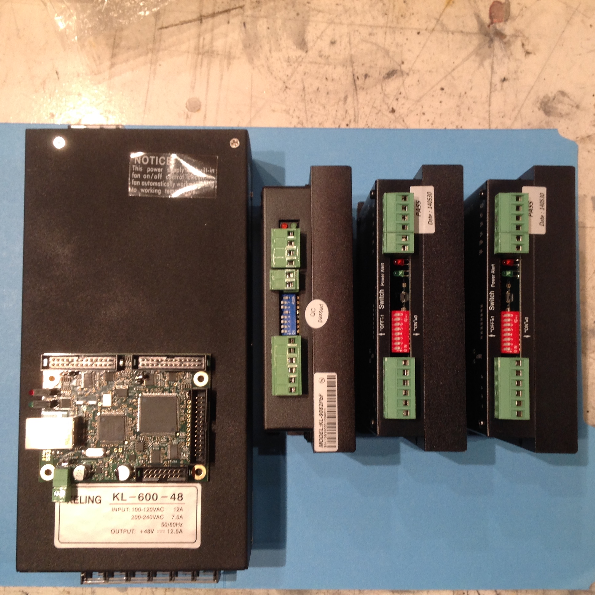
I went all through the specs and design to try to figure out why I would ever need one of the commonly used “breakout boards” sold as part of CNC driver kits, but could not come up with one. As long as voltage levels are correct and no stressful input signals applied, I can just drive the motor drivers from the Smoothstepper. That has worked well in practice.
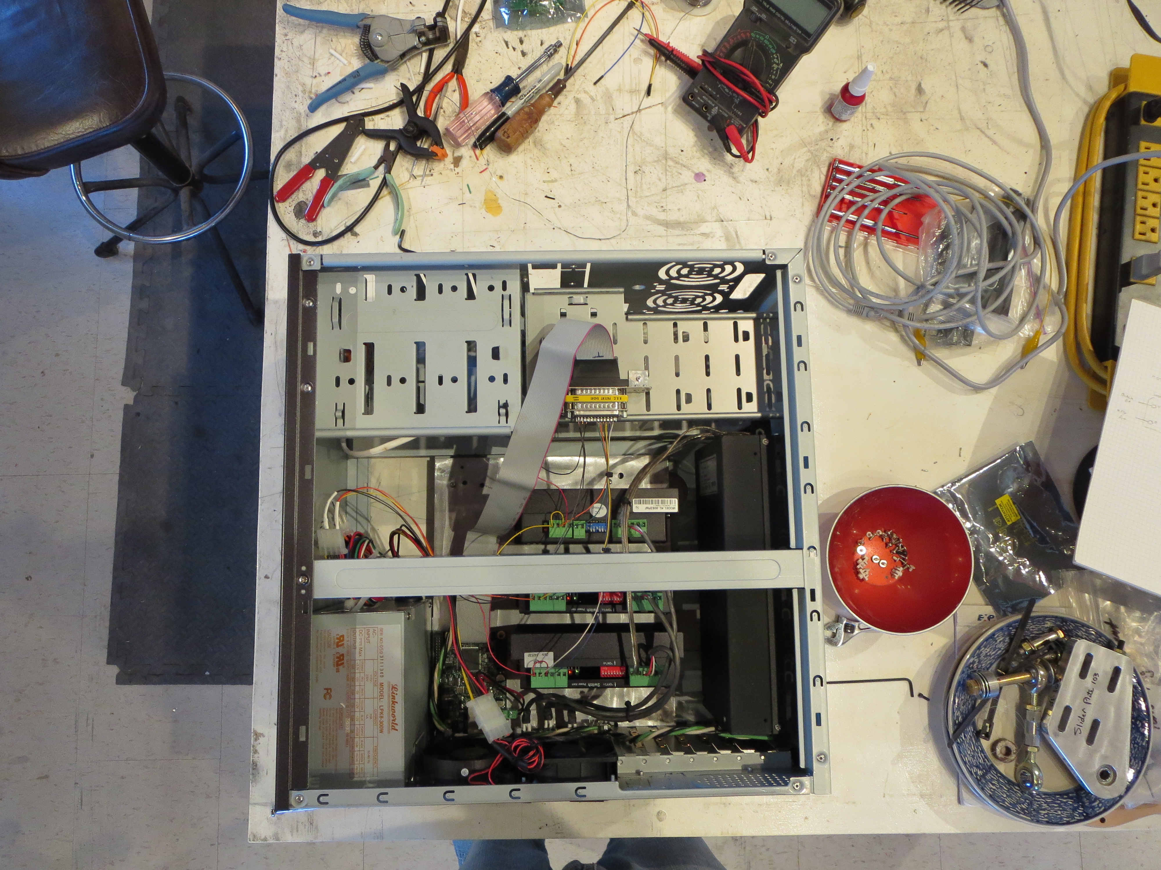
Instead of a breakout board I simply use a DB25 breakout with the wires soldered directly. The Ethernet Smoothstepper has a ribbon to DB25 cable, which is then connected to my DB25 breakout. It’s all wiring, with no discrete actual circuitry needed as long as you are careful about voltages and levels. For example, the low side of the STEP and DIR signals are connect to the SS. The high side is connected to the PC supply 5V. That way the SS is sinking current, not sourcing it, which is easier on the drivers.
I may have to add a voltage condition circuit to condition the signals when I add a Z-axis tool height detector later on.
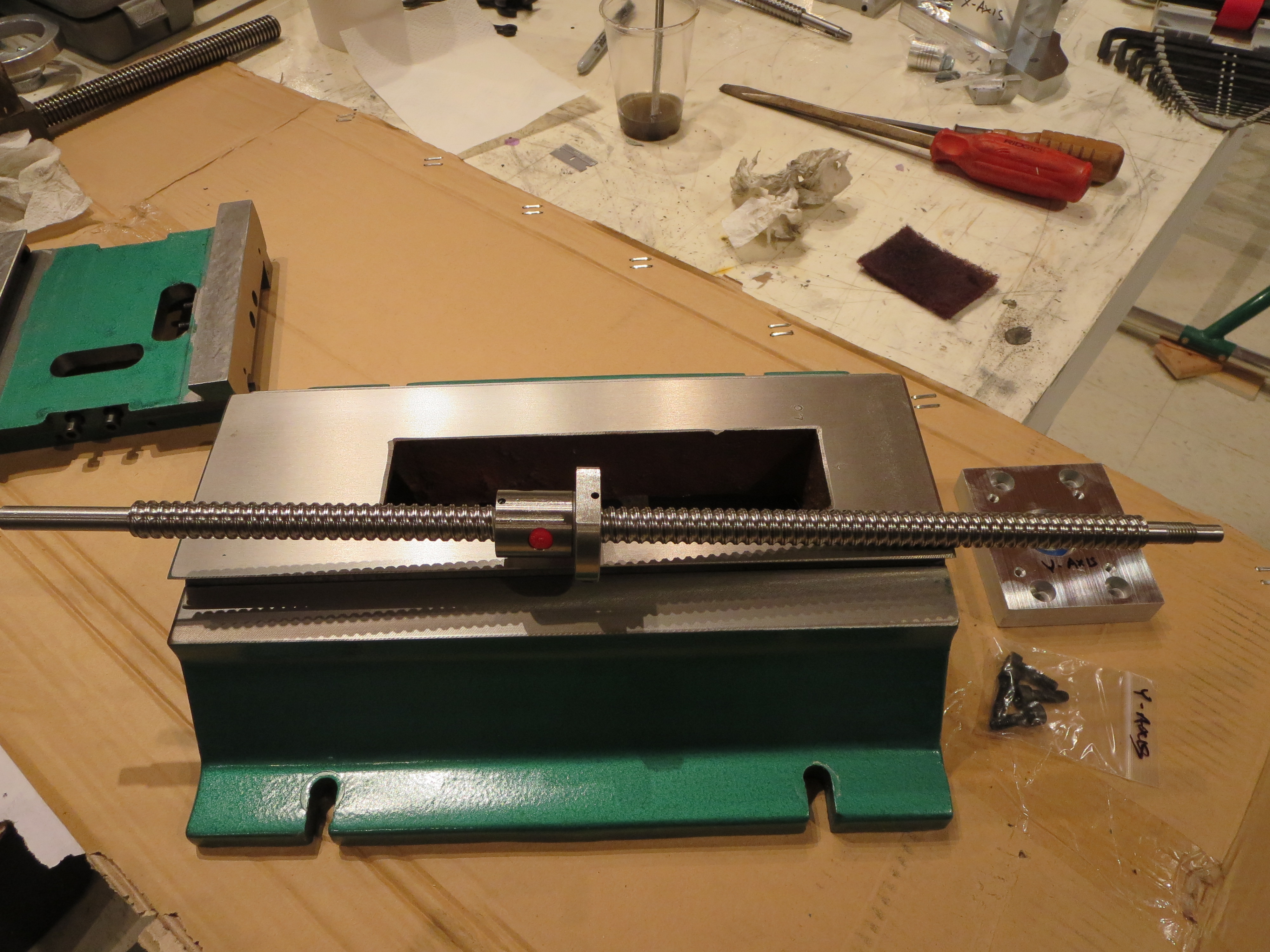
Shown in the picture to the right is the Y-axis motor mount bearing block which mounts on the rear of the casting. It’s a simple rectangular block with a bearing recessed and mounted.
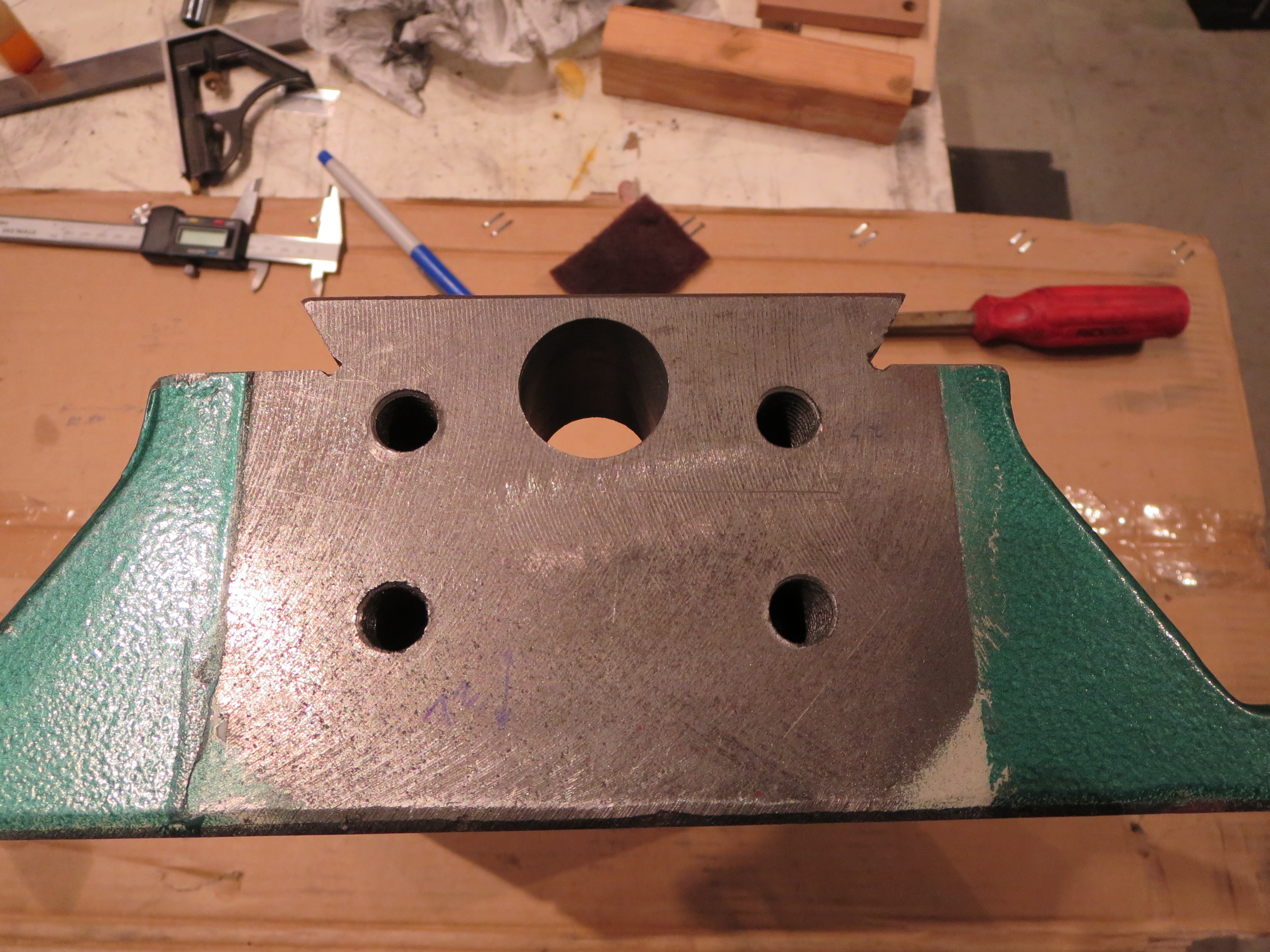
It turns out that drilling cast iron is a cinch. Drill residue is grainy, not nice curls like steel or aluminum. Drill dry, otherwise all that grit plus a lubricant would form a tool-killing abrasive. Blow out the hole often. This is a messy process.
You need a drill press and must clamp the hell out of it. Then just step up through the drills starting with maybe 1/8”. That 3/4”, then 1” bit really had my drill press working hard at low speed. Very satisfying perfectly bored and smooth hole when done.
Not shown is the matching hole that had to be drilled in the column for the ballscrew to also pass through. After drilling the base hole, the hole in the column was a stone cinch. Measure, measure, measure.
Every ten minutes of time spent measuring save hours and hours of rework, or worse; a damaged piece.
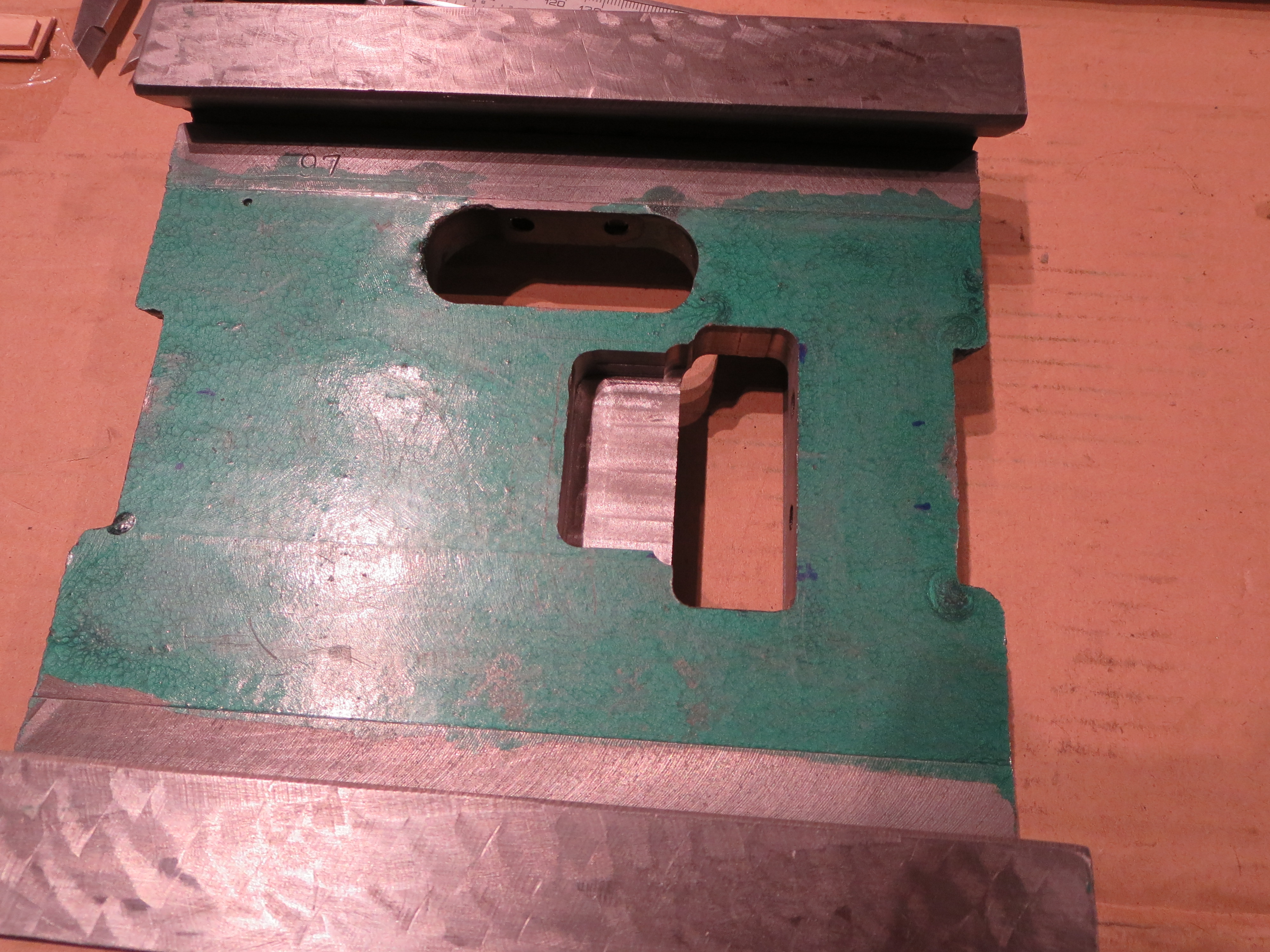
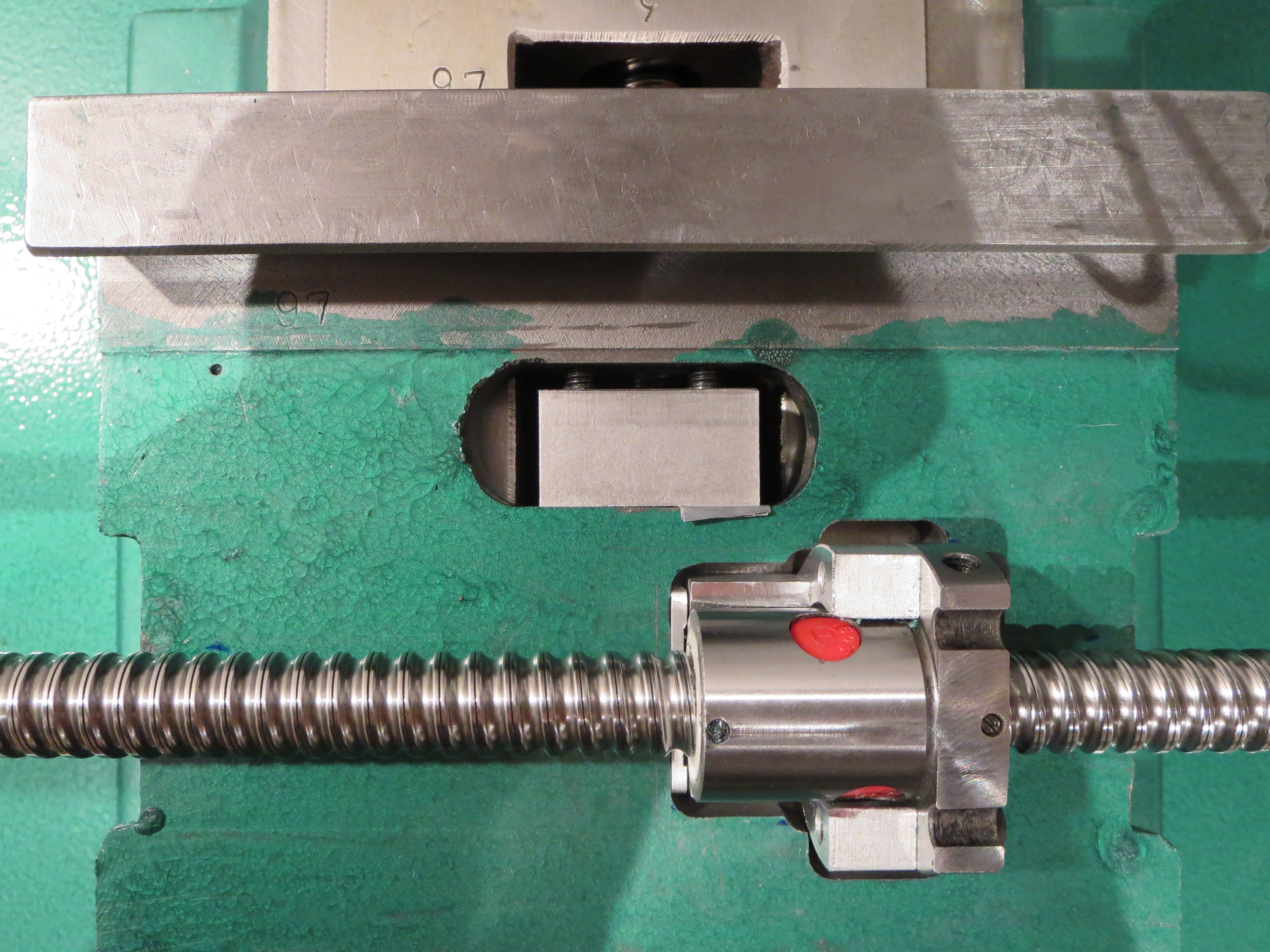
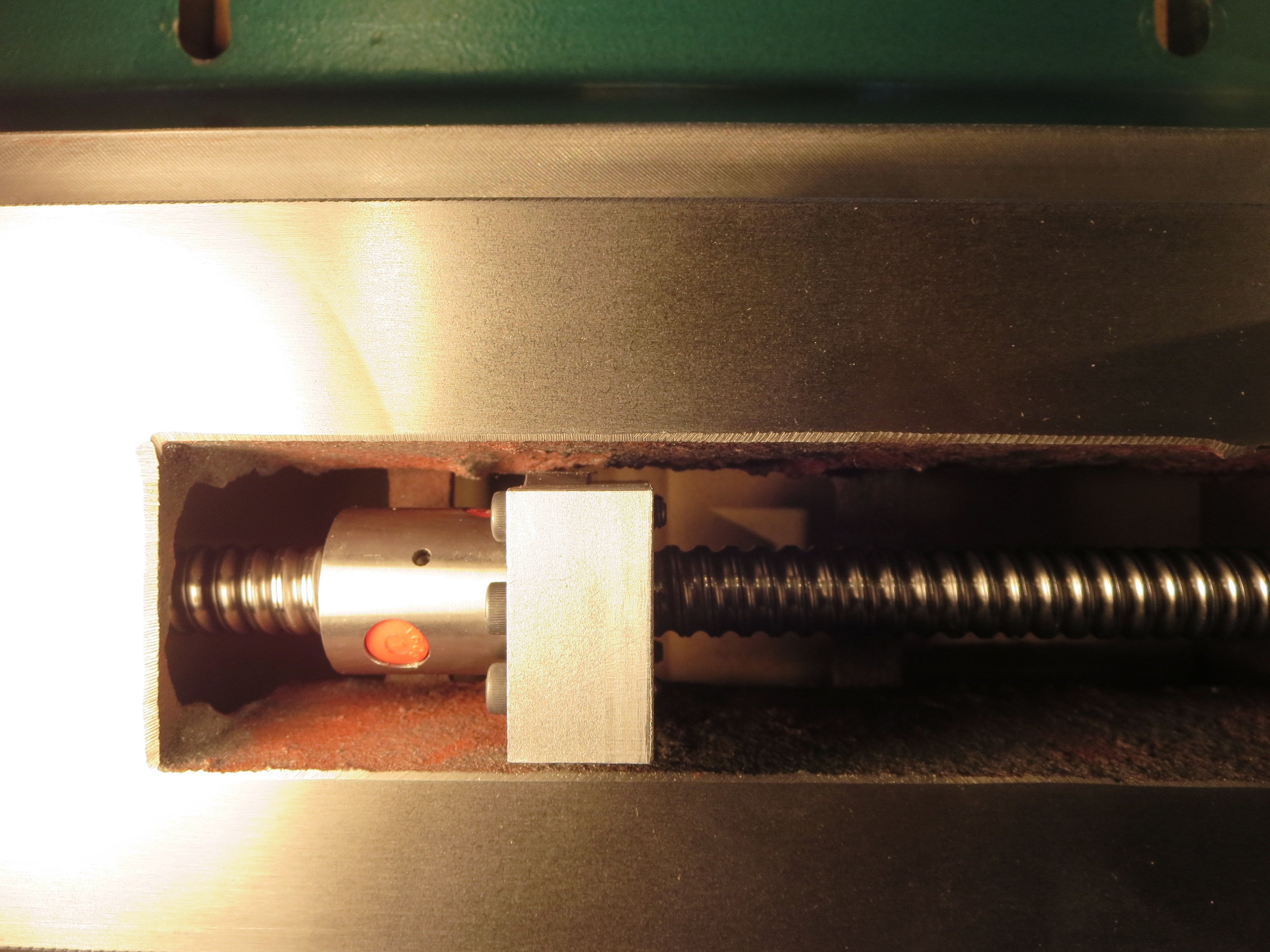
You can see a small shim to the right of the Y-follower nut. There was a bind without it as the cutout was not perfectly square as delivered from the factory. The Y-axis being short, and with 3 “hard” points, is very sensitive to alignment. Run it to all extremes and tighten one thing down at a time, dealing with any binding as it occurs. Try to visualize what is causing the bind. It is often not the last thing you changed, but a couple of steps prior, and then revealed on the last step.
Doing this with the X-Axis is a little tougher as you have to mount the table, check it, then pull the table off to adjust. You can see a little shim on the left side of the X-Axis ballnut pocket that is actually cut at a very slight angle to keep the X-screw in line.
I can’t emphasize this step enough. I went from a turn-bind-turn-bind rotation of the handles to a silky smooth binding free table motion in both X and Y. True - it took maybe10 hours of playing around to get it- but the results were very satisfying.
I also discovered (the hard way) how ballnuts are made since the first time I tried this I didn’t have the end of my plastic “keeper” square enough and a course of balls dropped through it. Thankfully I was doing this on a towel and captured all the balls. That was a three hour process to research “re-packing ballnut” on the web and then actually doing it. Just be careful and take your time. I also recommend doing that web search on those topics when you are alone. There are all types on the internet.

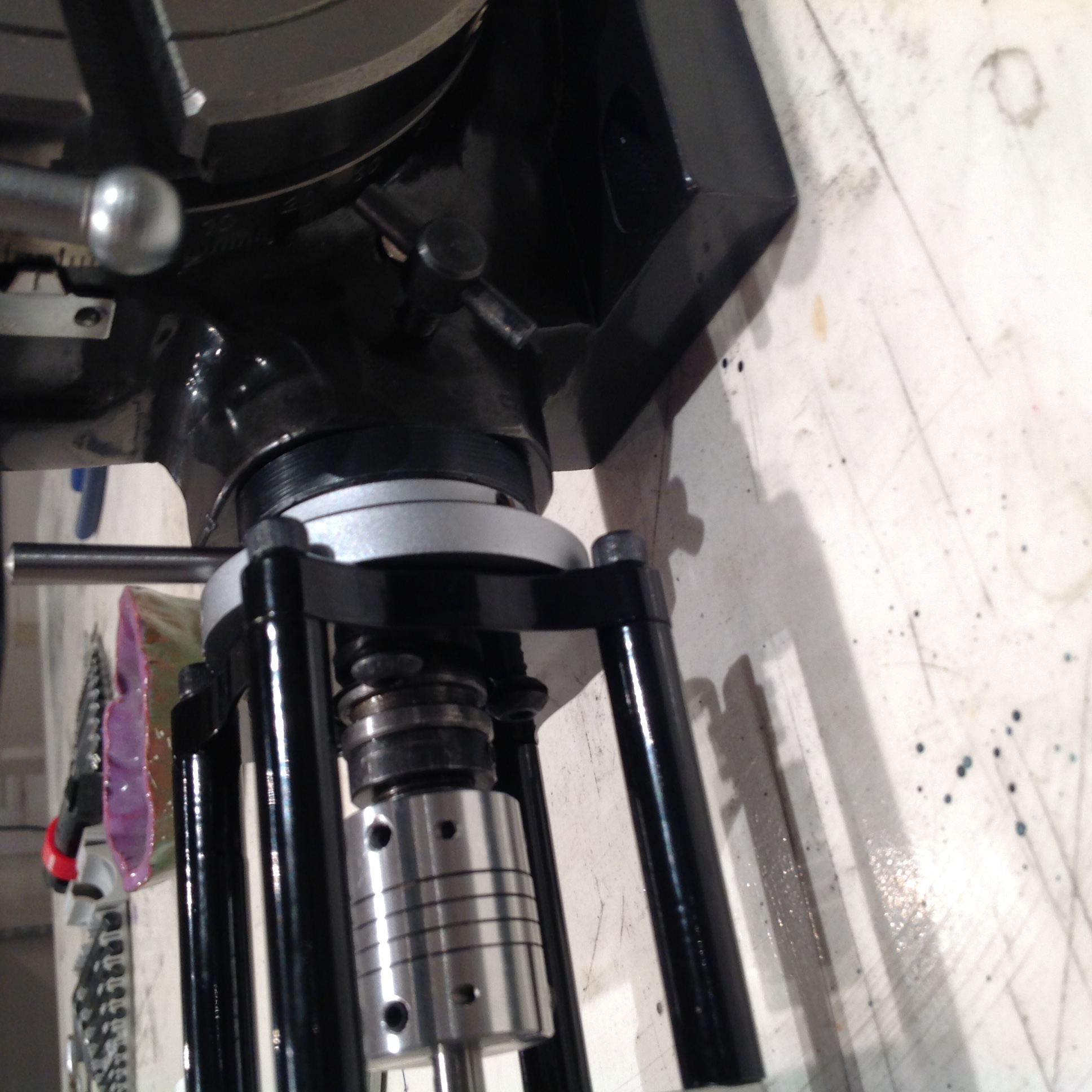
I think I am doing the “break-in” procedure in this photo.
This is all rough with the wires not dressed. Turns out I DID have to pull apart the head/Z-axis again as the astute viewer will notice that I forgot to install the black accordion-like column protector. That can’t just be “clipped on”. It has to be slipped on over the Z-ways from the top. I felt it was important enough to warrant taking it apart and installing.
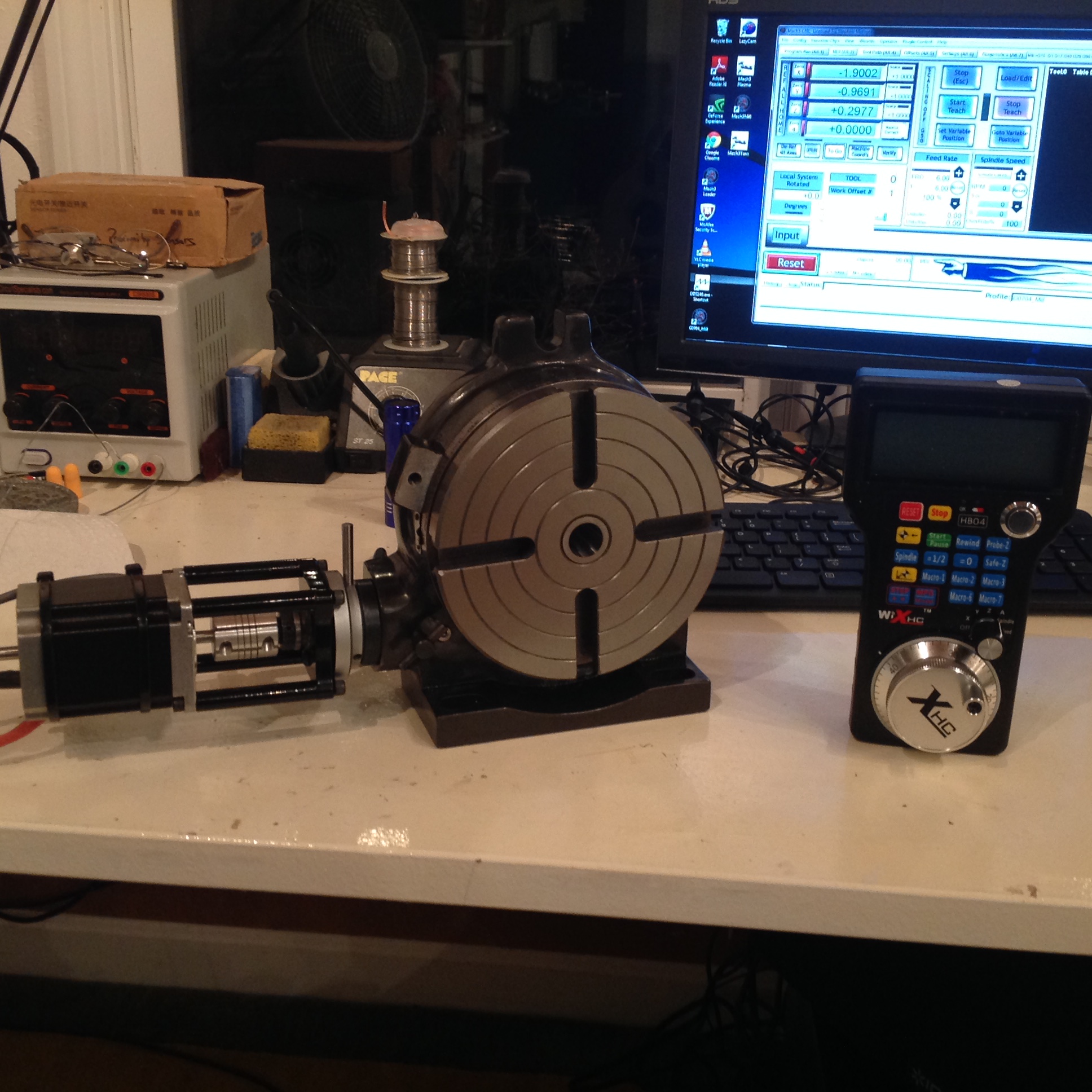
It was important to me to retain manual operation of the mill when deciding how to do the conversion. Now that I have the conversion complete, I can see that manual operation with the handles is not important at all. The handheld pendant I use allows me to “Virtually Turn” the handles and has a DRO readout on it. Manual operation is not at all necessary with that device.
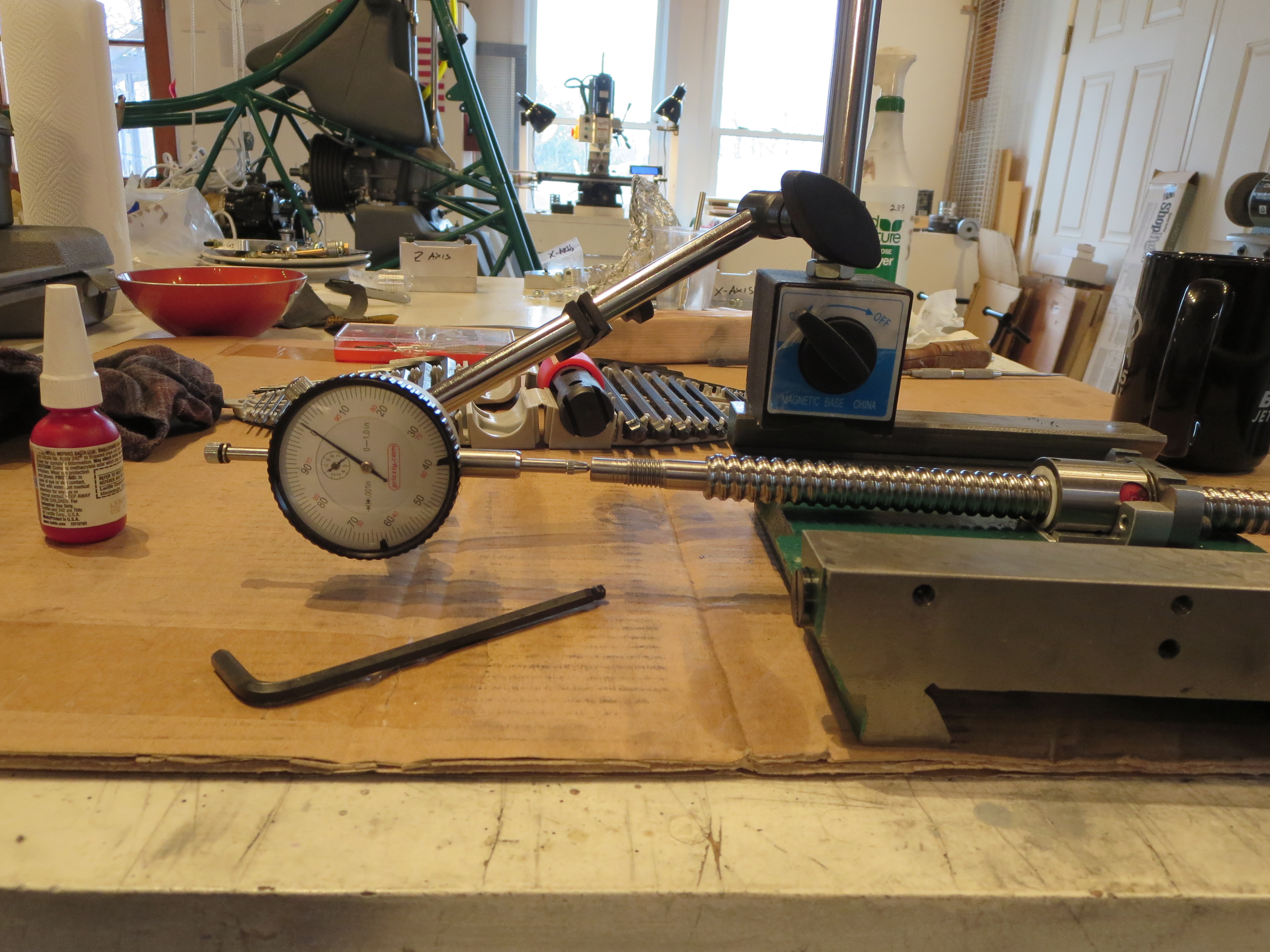
Spin the chuck (by hand) and look at the total deviation, plus and minus. Put the zero indication on the dial indicator squarely in the center of the total needle travel. It should then be on the average centerline of the shaft.
Run the head up and repeat the process. At the other end of the travel, spin the chuck and see where the center of the deviation is. It will likely not be where it was at the initial location. Loosen the head rotation nuts and bump the head. Repeat the measurements until the average centerline at one end of the travel is the same as at the other end of the travel.
Alignment is achieved and can be demonstrated by placing the need on the average centerline at one end or the other. Then, if you are in line, the needle should not move as the head is moved to the opposite end. It is like magic when, after all that fiddling and diddling, it stays on zero as the head moves up and down.
Since you are rotating the chuck to determine the average centerline, you are effectively canceling out errors by having a not uniform, or (very) slightly bent, alignment shaft. Polishing the shaft helps the needle slide up and down smoothly without a lot if jiggling back and forth.
Once the head is trammed to the column, you can then tram the Y-axis. This is WAY more involved as it means loosening the column mount bolts and shimming the column to adjust the fore-aft tilt of the column to achieve squareness. The goal is that as you move the workpiece mounted on the table from one extreme in Y to the other extreme in Y the distance between the mill bit and the table is uniform. I used both the shaft method (from above only with the indicator referenced to the table instead of the column) and the indicator as shown below in the X-tramming procedure.
The Y was actually very close to being in tram on first assembly. There was maybe a 0.0015”deviation across the Y-travel. You have to think about which side is up or down and therefore which side of the column mount needs shimming. It’ll take a bunch of tries. On my first try I way “over shimmed” and to go back to no shims to see if anything mades sense, then iterate my way to the correct amount. It took about 5 passes with different shims and different sequences of tighter in the column bolts.
I ended up with 3 layers of tinfoil as my shim between the column and the base right at the top of the base (right behind the Y-ways). That’s not a lot of displacement, but was what was required to bring the Y tram within 0.0005” across the full Y travel.
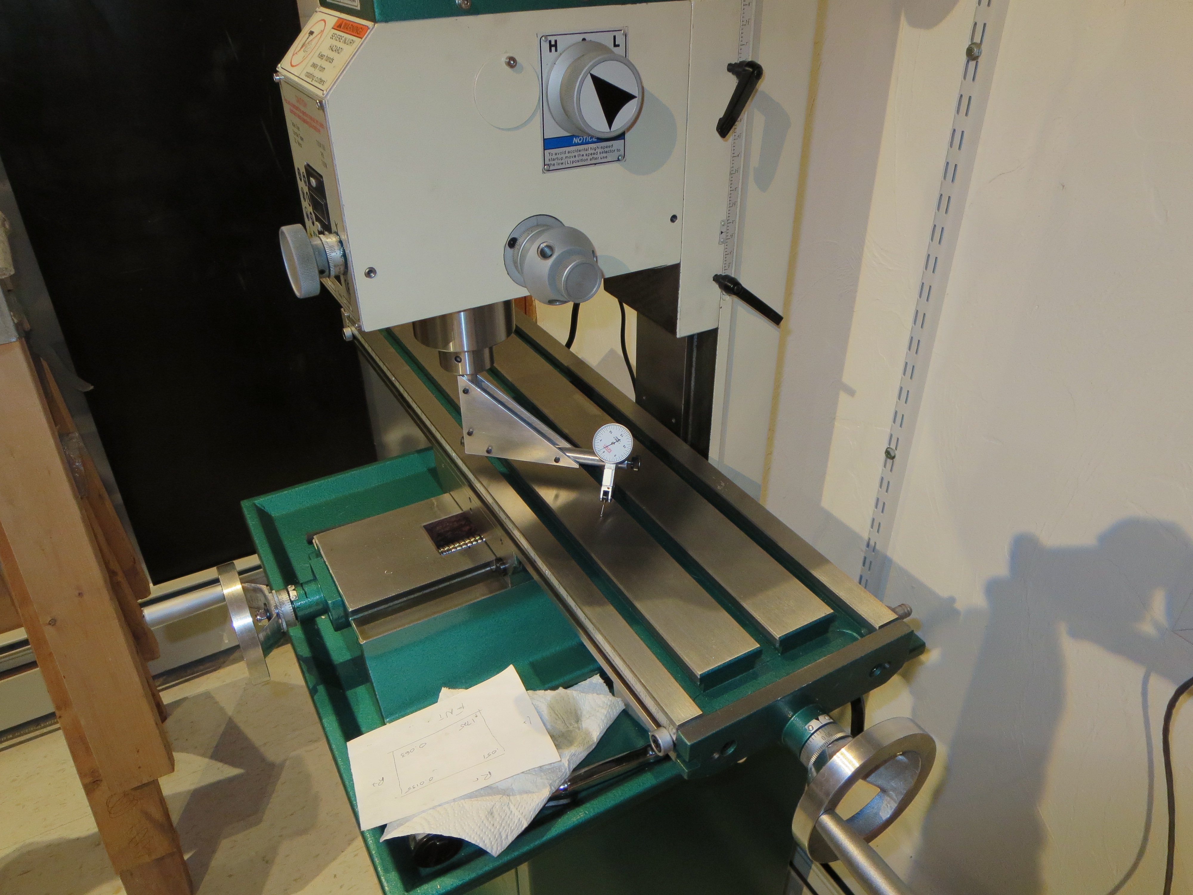
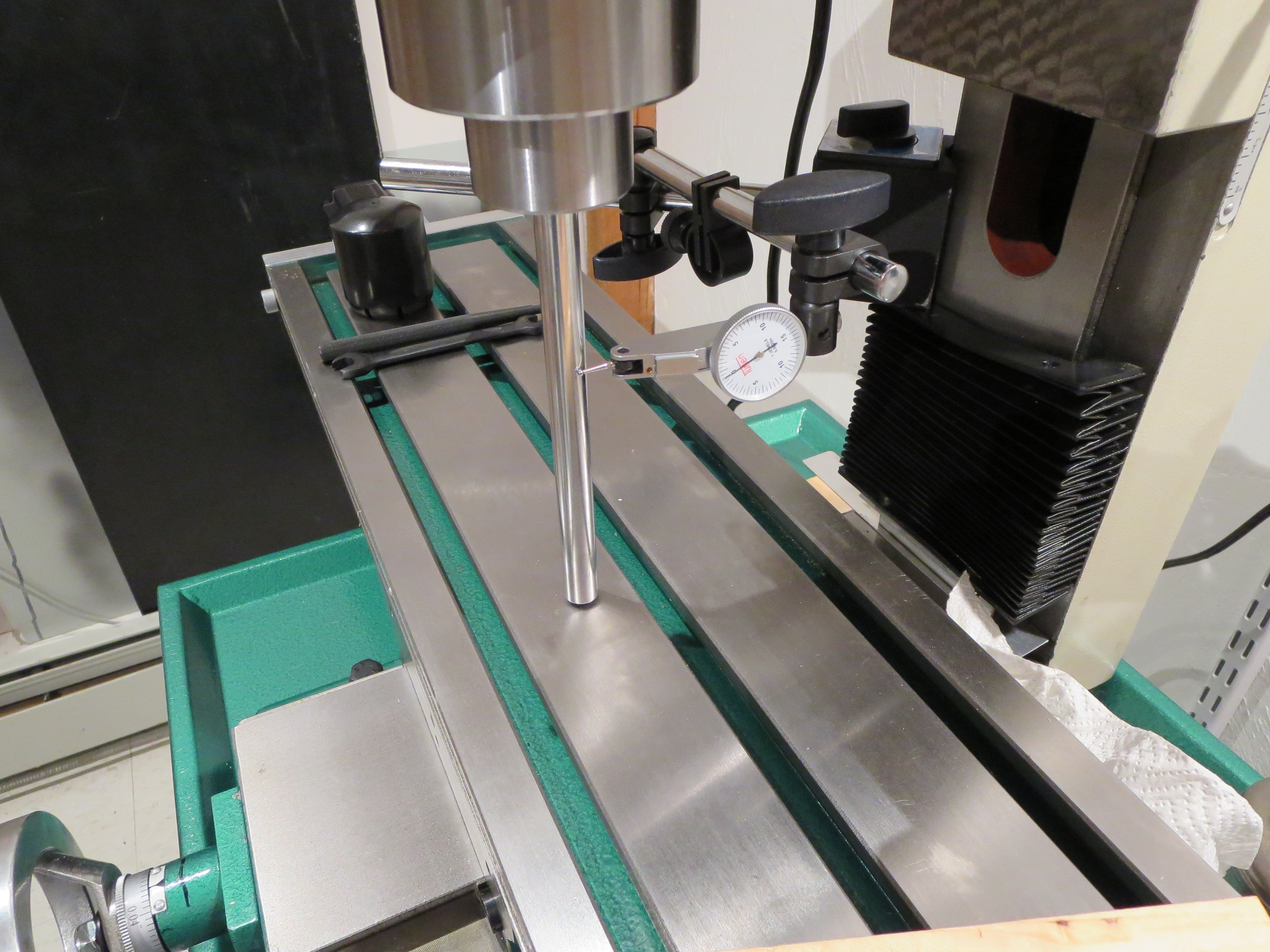
Over the roughly 10 inch span between left and right extremes of the indicator I bumped until the X-tram was less than 0.0005” different between the extremes. That’s really very little across that long a span. Any slight deviation (like asymmetric tightening of the column bolts) throws that off. Tighten everything slowly and in steps, checking the tram between each little bit.
Ready to cut metal!

My tool flow is:
- SpaceClaim - 3D design. Can’t say enough good about SpaceClaim. I am very productive with that tool.
- Spaceclaim export to VCP format through a plug-in
- Visual Mill EXP version. Visual Mill looks to be very capable. I am just learning it and am certainly not fluent or competent in it yet, but I have the flow down now after much experimenting.
- MACH3 for machine control - MACH4 is out now, but Mach3 has an enormous amount of support, peripherals, and add-ons whereas Mach4 does not.
I wanted to do a piece that would be difficult/impossible to mill by hand. There are 4 tools employed; center spotting drill, 0.196 twist drill, 0.25” flat End Mill, and a 0.25” chamfer bit.
Visual Mill placed those mounting tabs to keep the piece attached to the blank. They are only 0.100 thick and were Dremel-ed through on completion.
I am spoiling myself. In the past when I would do something like this with hand tools, there would be a lot of measuring, laying out, then fabricating; followed by a ton of fitting with a file and sandpaper and maybe re-manufacturing the parts. It would look “homemade”. With the precision of the machine tools I have now, lay it out, fabricate it, and it virtually falls together. Nice.
With the full CNC mill working well I am declaring this project CLOSED. It took almost 2.5 months of time away from the helicopter and I am feeling neglectful, but I have all sorts of widgets that I plan on making for it now that I have a very formidable new capability in the shop.