
Electronic Compass
02/10/13 17:11 Filed in: All
Detour into Electronics Land. For several months I have been tied up doing other projects keeping me away from the helicycle and then started looking into the panel instruments.
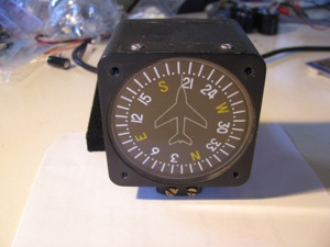
Every aircraft seems to have one of these, so I just assumed I should get one as well, so bought one from Wentworth on eBay for about $200.
It’s awful. Sticky motion and inaccurate (+/- 5 to 10 degrees). Now this one is used, and does not work as well as the one in my plane, but - damn - there has to be a better way to tell direction than sticking one off these butt -ugly devices on the top of the instrument pod.
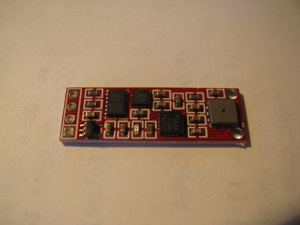
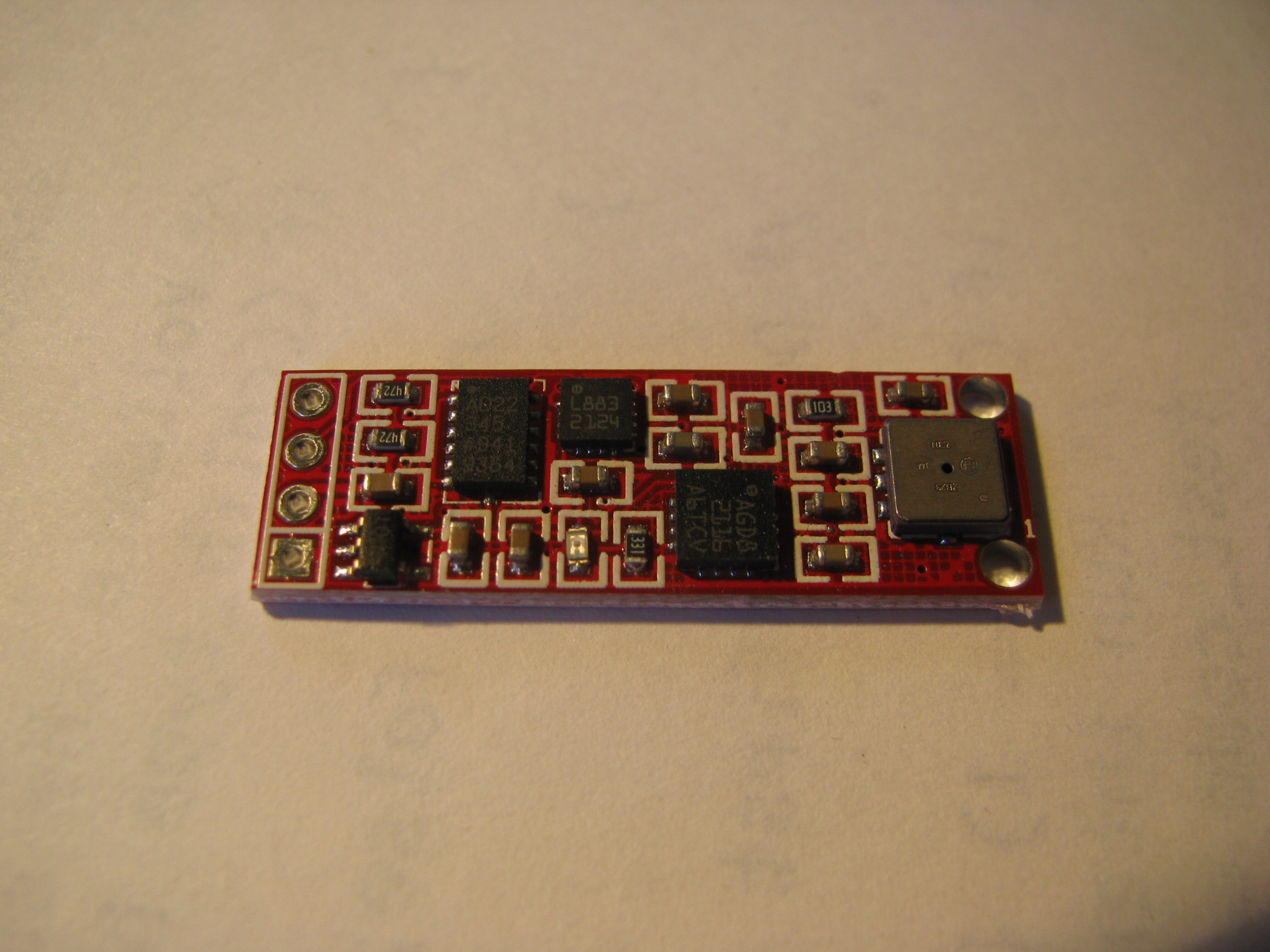
Looking around the web revealed these little gems. This is basically an inertial navigation system on a little 1.5cm x4cm card.
Onboard there is a compass chip, a 3-axis accelerometer, a 3-axis rate gyro, and a barometer that tells temperature as well. All this for <$20.
Seems like one should be able to build a compass out of this pretty easily.
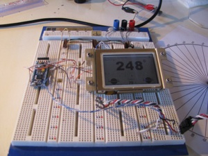
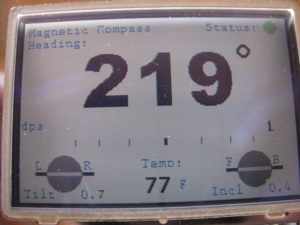
I took the opportunity to learn about the Arduino. Neat little micro - fairly self-contained with a well-developed open-source IDE. That‘s a sunlight readable LCD from EARTHLCD.
The display is driven by a serial line from the Arduino and the IMU module is interfaced via I2C. All-in-all some very simple wiring to get the whole mess working. Of course this will all get packaged up cleanly before installation for real.
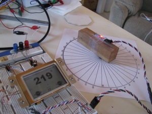
The test jig. The rose is calibrated with a fluid compass to point North. The IMU is just taped to a block of wood. It’ll be mounted up in the nose of the instrument cluster pod.
I learned a lot about the earth’s magnetic field and compasses. I did not realize that the primary magnetic force vector points 70 degrees downward at my position on the planet.
What that means is that the compass works well if level, but is WAY off if tilted by even a degree or two. The solution is to use Z-axis of the magnetic field reading and the accelerometer to detect tilt. Then do the 3-D vector trigonometry to correct and compensate for the tilt.
All of this is a lot of math and was a good challenge. It’s been years since I did matrix operations and lots and lots of trig.
In the center there is a turn rate bar that varies in proportion to the rate of angular turn. Just like in a commercial gyro, the 3dps reading is a half scale bar. The bar deflection is proportional to the rate of turn and the displacement scale is exponential. The tilt readings are displayed since I had to compute them for the compass anyway. I calibrated the tilt against my $200 digital level and it is just as accurate.
For the uber-weenies out there, the code is attached. I make no license or warrantee that this will work for you. It works for me and that’s all I care about right now.
Air_Instrument5.ino Main program with primary execution loop
ADXL_Support.ino Support routines needed for accelerometer device
AI_Support.ino General purpose routines and conversions
AI_Types.h Data type definitions for passing vectors around
BMP085_Support.ino Routines for handling the barometric and temp sensor
Compass_Support.ino Routines for initializing, calibrating & reading the Compass Device
EZLCD_Support.ino Display device routines and drawing methods
Gyro_Support.ino Routines for driving the rate gyro device
I am extra-happy with the tilt compensation. You can now tilt the device (and ultimately the helicopter) up to about 70 degrees off level in any direction and the magnetic heading is still accurate. There is NO mechanical compass I know of that has that sort of performance envelope. Along the way I learned a ton. I plan to use that knowledge to build an airspeed indicator accurate to 5mph or less.

Every aircraft seems to have one of these, so I just assumed I should get one as well, so bought one from Wentworth on eBay for about $200.
It’s awful. Sticky motion and inaccurate (+/- 5 to 10 degrees). Now this one is used, and does not work as well as the one in my plane, but - damn - there has to be a better way to tell direction than sticking one off these butt -ugly devices on the top of the instrument pod.
Looking around the web revealed these little gems. This is basically an inertial navigation system on a little 1.5cm x4cm card.
Onboard there is a compass chip, a 3-axis accelerometer, a 3-axis rate gyro, and a barometer that tells temperature as well. All this for <$20.
Seems like one should be able to build a compass out of this pretty easily.

I took the opportunity to learn about the Arduino. Neat little micro - fairly self-contained with a well-developed open-source IDE. That‘s a sunlight readable LCD from EARTHLCD.
The display is driven by a serial line from the Arduino and the IMU module is interfaced via I2C. All-in-all some very simple wiring to get the whole mess working. Of course this will all get packaged up cleanly before installation for real.
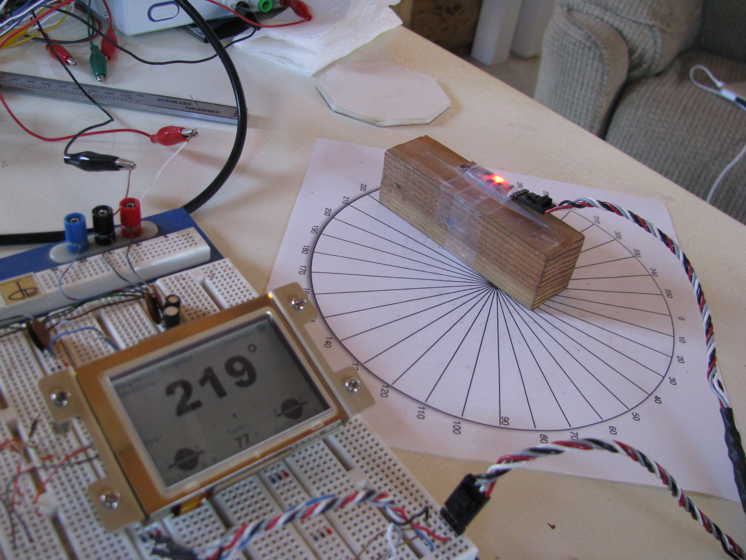
The test jig. The rose is calibrated with a fluid compass to point North. The IMU is just taped to a block of wood. It’ll be mounted up in the nose of the instrument cluster pod.
I learned a lot about the earth’s magnetic field and compasses. I did not realize that the primary magnetic force vector points 70 degrees downward at my position on the planet.

What that means is that the compass works well if level, but is WAY off if tilted by even a degree or two. The solution is to use Z-axis of the magnetic field reading and the accelerometer to detect tilt. Then do the 3-D vector trigonometry to correct and compensate for the tilt.
All of this is a lot of math and was a good challenge. It’s been years since I did matrix operations and lots and lots of trig.
In the center there is a turn rate bar that varies in proportion to the rate of angular turn. Just like in a commercial gyro, the 3dps reading is a half scale bar. The bar deflection is proportional to the rate of turn and the displacement scale is exponential. The tilt readings are displayed since I had to compute them for the compass anyway. I calibrated the tilt against my $200 digital level and it is just as accurate.
For the uber-weenies out there, the code is attached. I make no license or warrantee that this will work for you. It works for me and that’s all I care about right now.
Air_Instrument5.ino Main program with primary execution loop
ADXL_Support.ino Support routines needed for accelerometer device
AI_Support.ino General purpose routines and conversions
AI_Types.h Data type definitions for passing vectors around
BMP085_Support.ino Routines for handling the barometric and temp sensor
Compass_Support.ino Routines for initializing, calibrating & reading the Compass Device
EZLCD_Support.ino Display device routines and drawing methods
Gyro_Support.ino Routines for driving the rate gyro device
I am extra-happy with the tilt compensation. You can now tilt the device (and ultimately the helicopter) up to about 70 degrees off level in any direction and the magnetic heading is still accurate. There is NO mechanical compass I know of that has that sort of performance envelope. Along the way I learned a ton. I plan to use that knowledge to build an airspeed indicator accurate to 5mph or less.