
CyclicControls
Controls Installed
03/03/14 00:19 Filed in: All
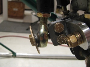
Installed the collective controls and cyclic controls in the ship for the "final" time.

Everything is torqued and safety wired. I put a dot of torque seal on the nuts after final installation. Since all the pieces had been pre-fit, it was very straightforward. The only annoyance was that one of the Grade8 bolts I had purchased pre-drilled really wasn't drilled all the way through. It demonstrated that the Loctite sets up very quickly. The portion in the threads was already gummy after only an hour or so after installation.

The control stick has almost no resistance fore and aft due to the bearings in the stick, but a slight amount in the left right since it is turning the cyclic shaft in the slider. It;s all greased well, and there is no breakout force, per se. We'll see how it all feels when the rest of the control arms and fittings are installed.

Everything is torqued and safety wired. I put a dot of torque seal on the nuts after final installation. Since all the pieces had been pre-fit, it was very straightforward. The only annoyance was that one of the Grade8 bolts I had purchased pre-drilled really wasn't drilled all the way through. It demonstrated that the Loctite sets up very quickly. The portion in the threads was already gummy after only an hour or so after installation.
The control stick has almost no resistance fore and aft due to the bearings in the stick, but a slight amount in the left right since it is turning the cyclic shaft in the slider. It;s all greased well, and there is no breakout force, per se. We'll see how it all feels when the rest of the control arms and fittings are installed.
Mixer Refit
02/16/14 22:54 Filed in: All
The original mixer (partially disassembled) looks fairly primitive next to the nicely CNC machined parts of the new one. I was never a huge fan of the single bolt in the center holding the "wings" together.

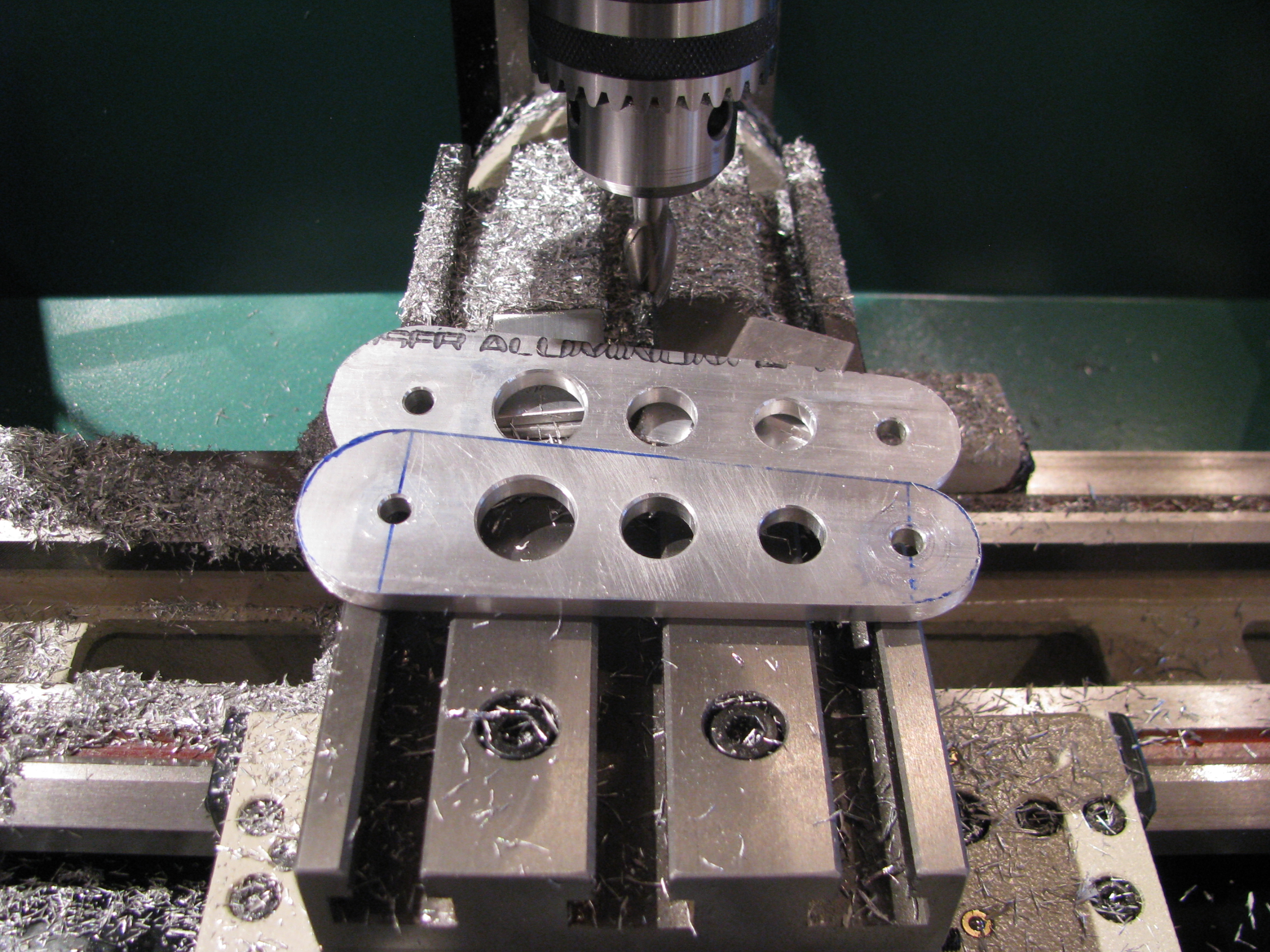
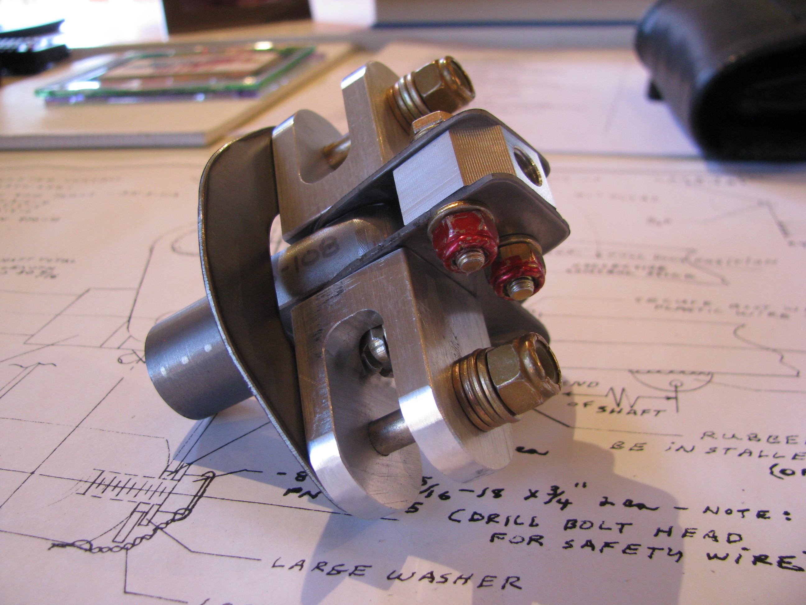
Start by drilling the hole for the safety wire on the fore/aft arm. On the collective slider I did them "free-hand". On this piece and with the mill and a couple of holding blocks this is achieved in very short order and with less hand wringing. Center punch the start location. Use a center drill to provide a "divot" so the real drill doesn't wander and away we go.
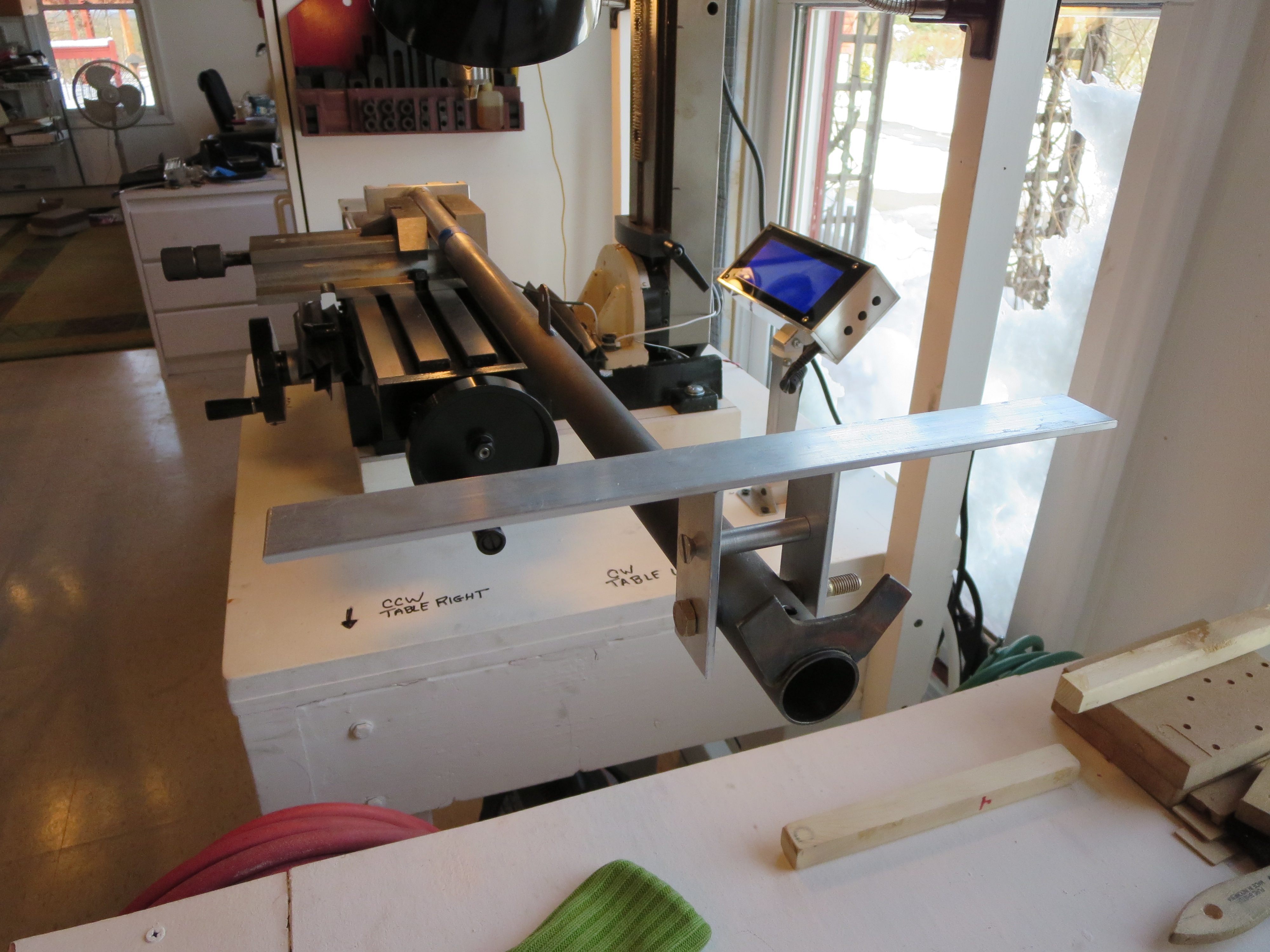
To precisely align the mixer with the control stick I made a little jig. Those two aluminum plates were machined in a stack, so they exactly match. The holes were drilled and the top edge machined to form a precise reference edge/plane. Both plates are exactly the same dimensionally. Then I made a little spacer on the lathe the exact same width as the cyclic bolt tube. Bolt 'em together and place a bar across the reference edges. My digital level was then used to get the angle between the reference and the bottom of the mixer block to exactly 0.0degrees.
Of course right when I was feeling smug and competent, BAM. The drill bit snapped off on the first hole. Crap! About half an inch into the hole. Of course you can't drill into a drill bit, so instead of boogering things up I stopped and stared at it for a while.
First I tried digging the broken bit out with a pick and needle nose pliers - no joy. Then I milled the hole slightly and the broken end of the drill bit. At least at that point I could remove the mixer block.
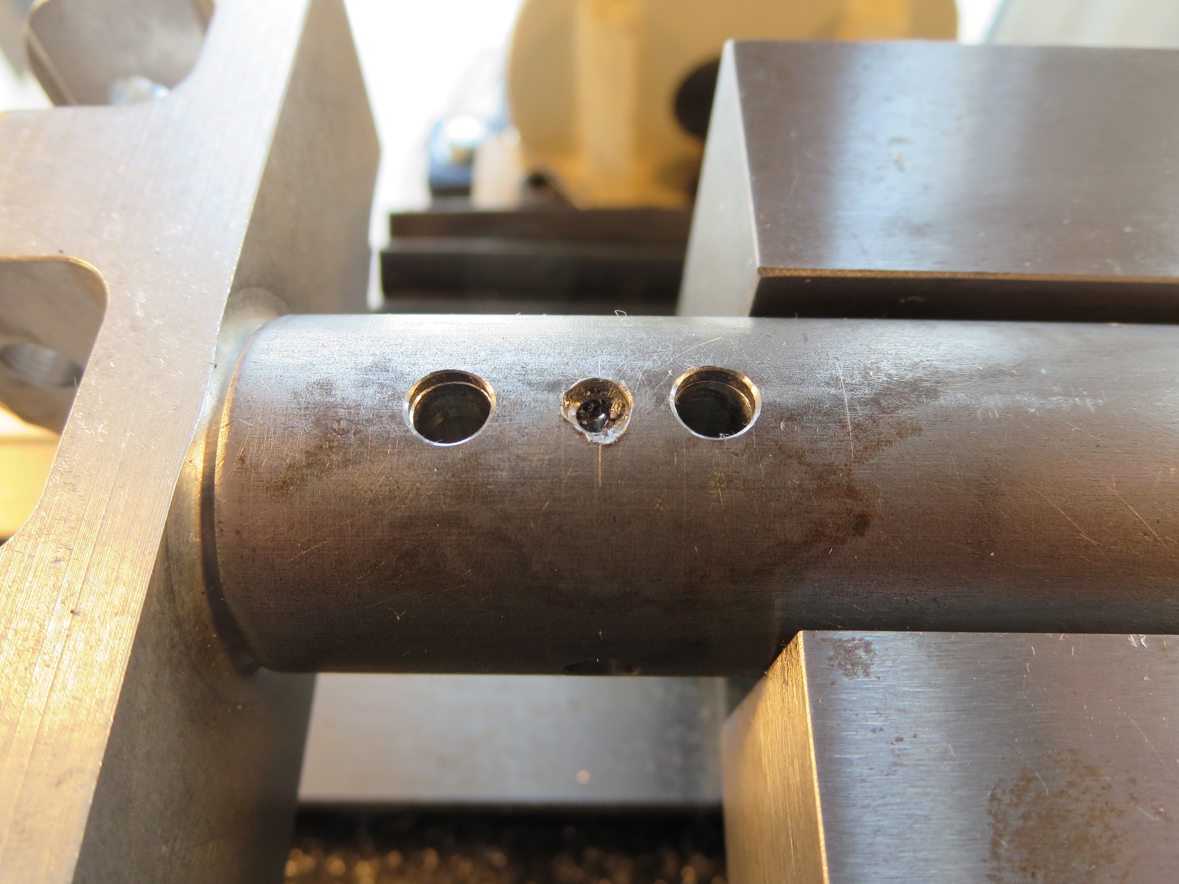
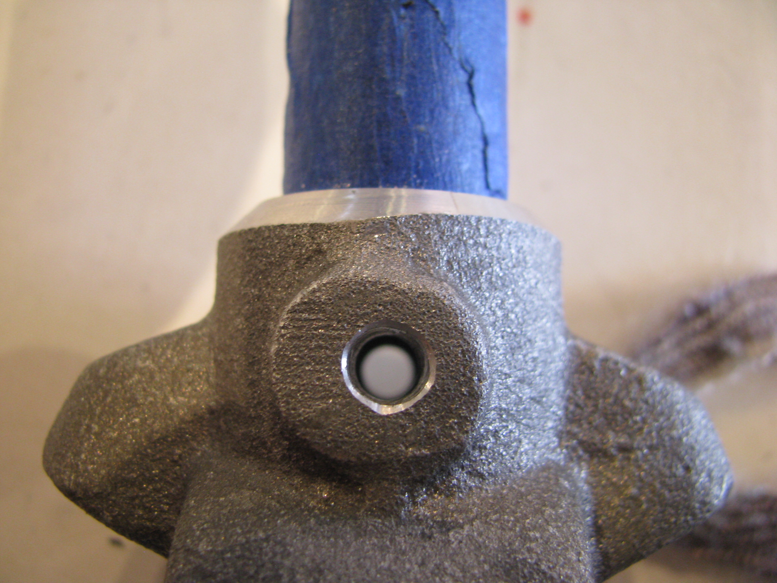
I tried using the "old" rearmost vertical hole first and matching the hole (you can see the hole on the left) Though very, very close, the hole on the other side of the tube was slightly oblong (by about 10 mils). I went ahead and drilled the horizontal cross bolt.

Why the bit snapped I don't know. It was only eating into aluminum at that point. It was well oiled, and I was backing it out regularly to clear chips. I was attempting to use a #30 bit as the pilot and that is probably a little wimpy for a hole this deep. Here you can see the remains of the broken bit with about 0.5" missing (in the mixer block).

Even though it probably would have been OK, I carefully measured and determined that there was room for a third hole in between the others. You can see the middle drill bit here showing that hole. Pretty busy. The forward most cross hole is perfect, nice and snug. The rearmost one is the one I tried to match - sloppy on the far side. The middle is my auxiliary hole - also nice and snug. OK. Good. Crisis averted.
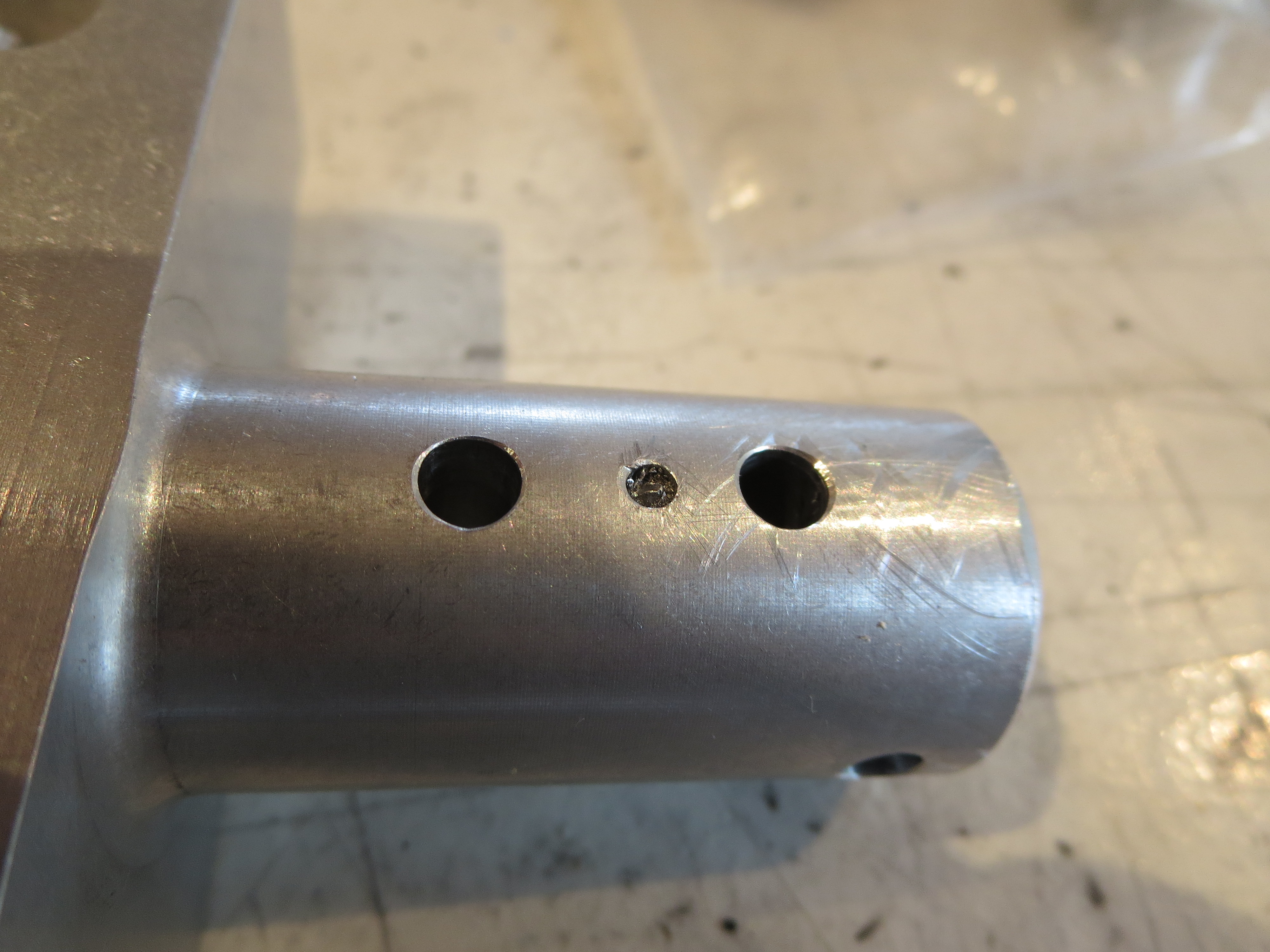
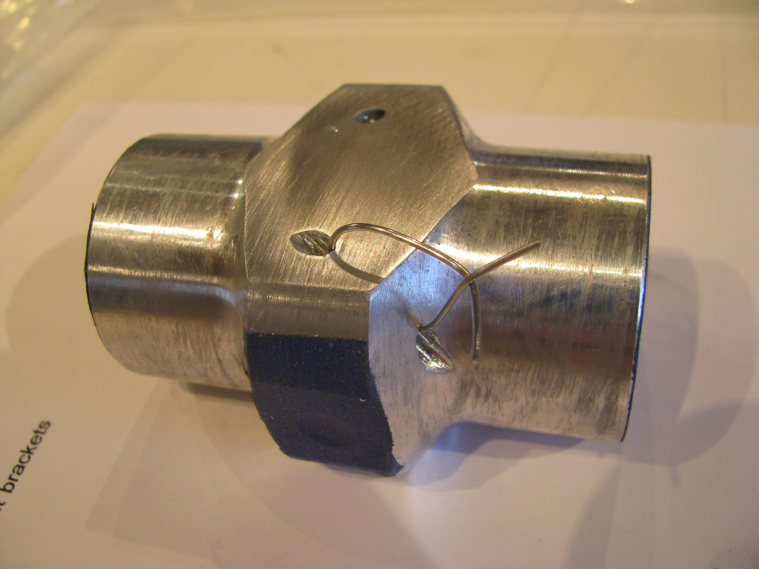
The mixer block removed from the cyclic control tube showing the three holes. Since it is solid aluminum I have no concerns over strength. The broken bit will ride along with me forever stuck in the aborted hole.
The rest of the mixer assembly is a non-event, just assembly with a little sanding to make everything slide together smoothly. Off to paint.
Received New Mixer
02/08/14 15:31 Filed in: All
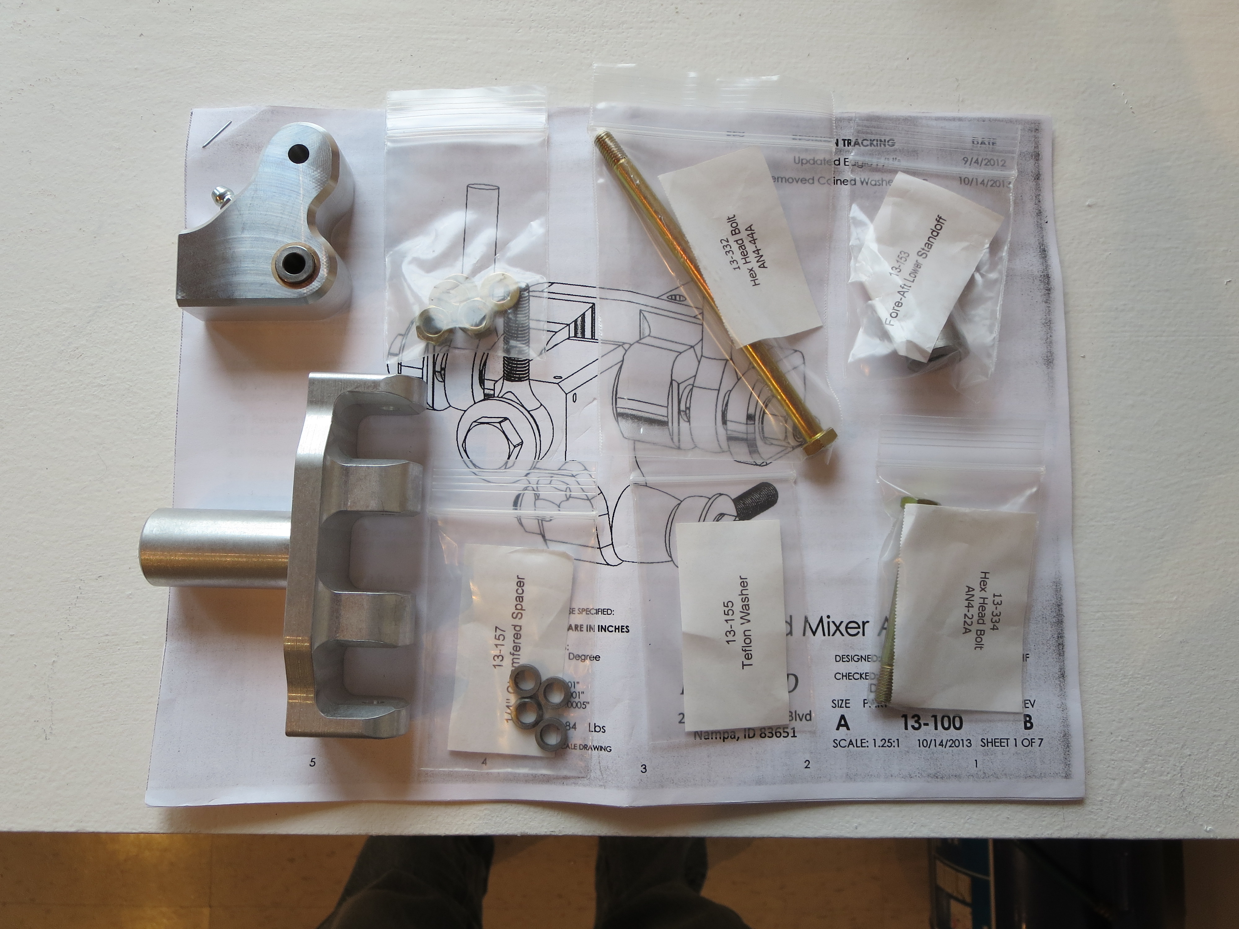
I finally received the new mixer from Blake. Very nice machined parts. What a quantum difference in quality of drawings CAD makes. Can't wait to slide al this together.
Control Rods
04/17/11 21:17 Filed in: All
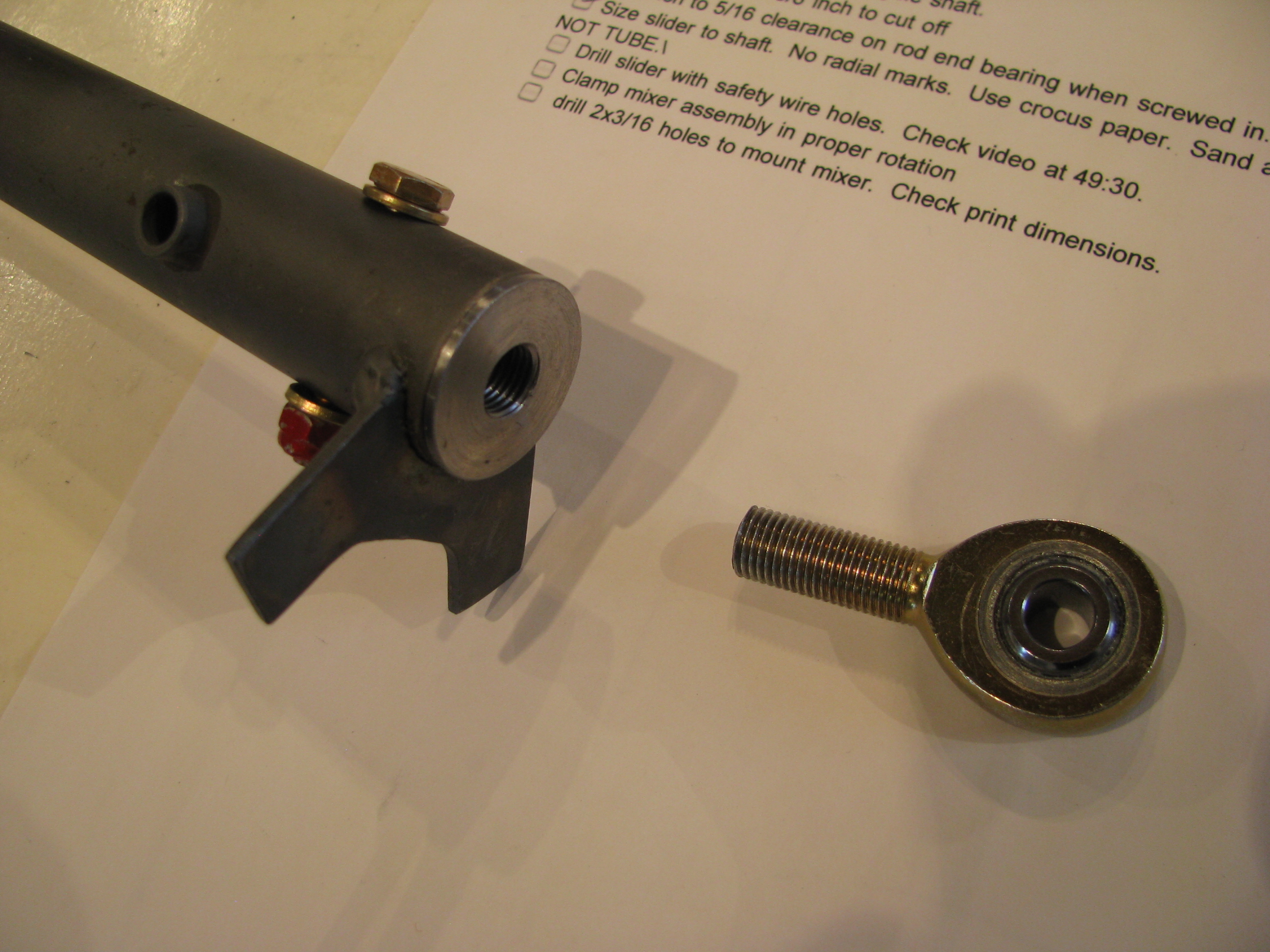
Here’s a really bad Idea I don’t recommend - dipping the end plugs in primer. Ever anal about corrosion, I thought this would be a good idea. Even though the primer is very thin, it’s enough to make screwing in the rod-end bearings very difficult. Two turns in and one back out, almost like retapping the plugs. Once cleaned out they’re fine, but I am sure it was hard on the threads.
Another commercial for the Grizzly mill/drill. Bolt together the walking beams, bolt to the table at 3.5 degrees and mill away. Afterwards 20 seconds on the belt sander and done. Careful as the edges on milled parts are razor sharp.
All you machine shop nazis can rail on me for not using the proper collet on the mill, but changing is a pain and I took very small cuts. Of course I would switch over for more extensive jobs.
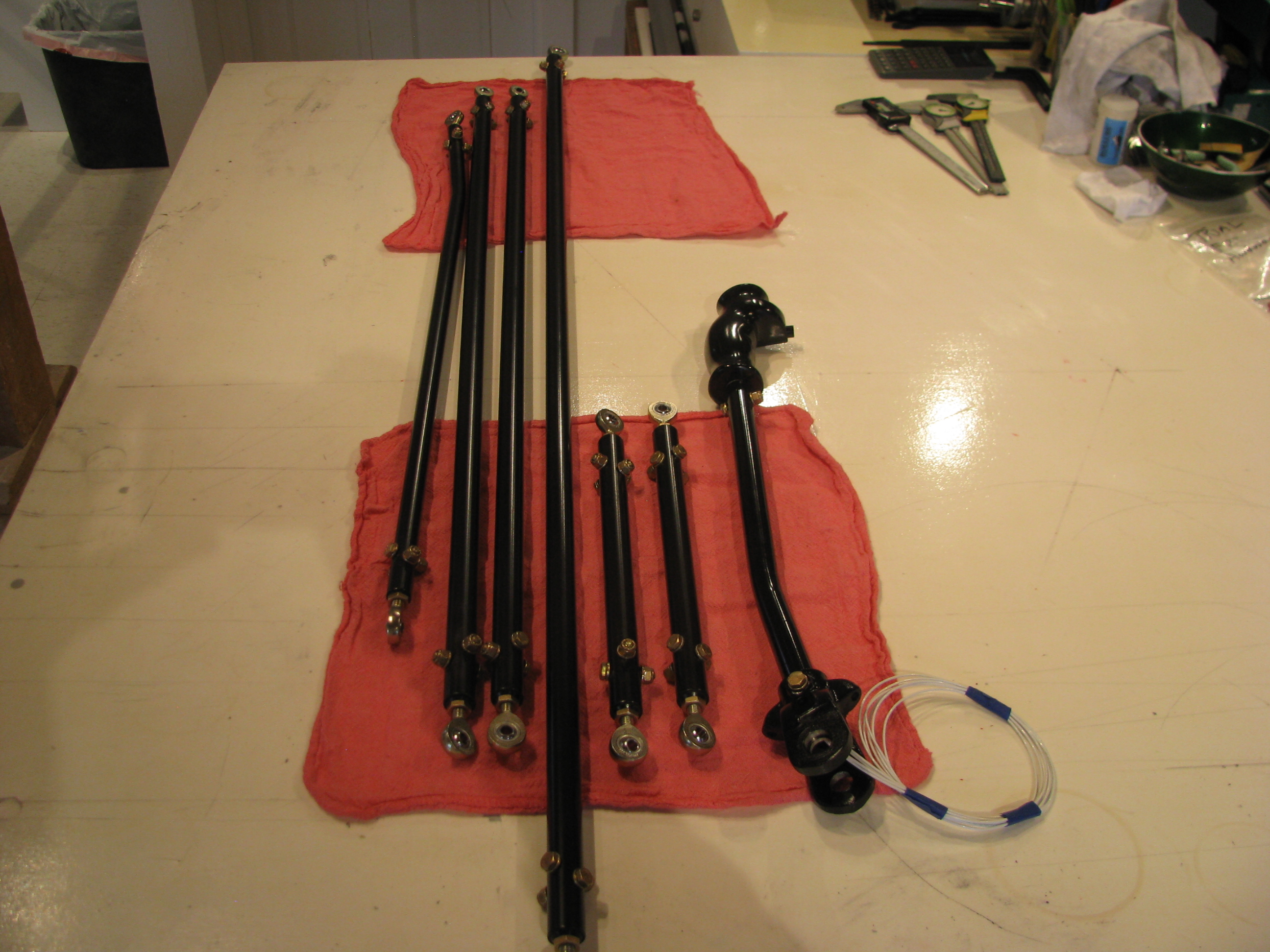
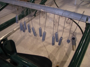
Parts starting to look finished - because they ARE finished. I know these will probably get dinged up during the continuous fitting/refitting, but the epoxy paint should be easy to touch up just before final assembly.
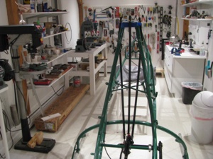
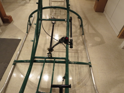
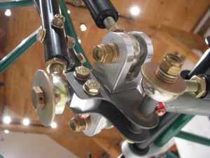
Cyclic assembly in ship with control rods preliminarily placed.
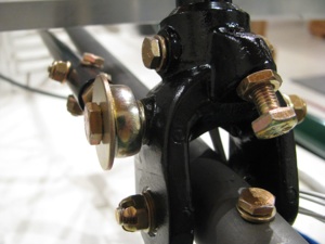
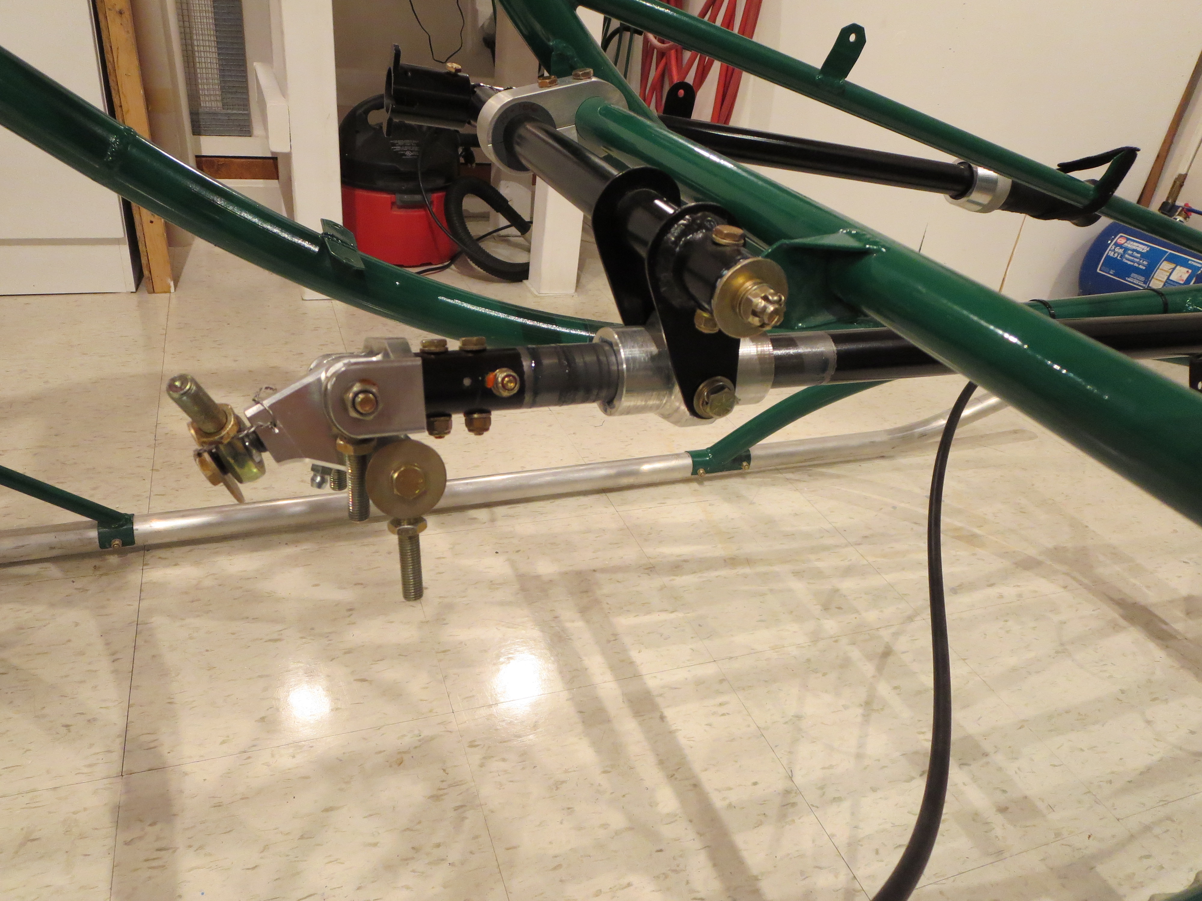
Front end of cyclic stick mounting.
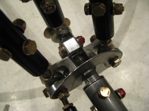
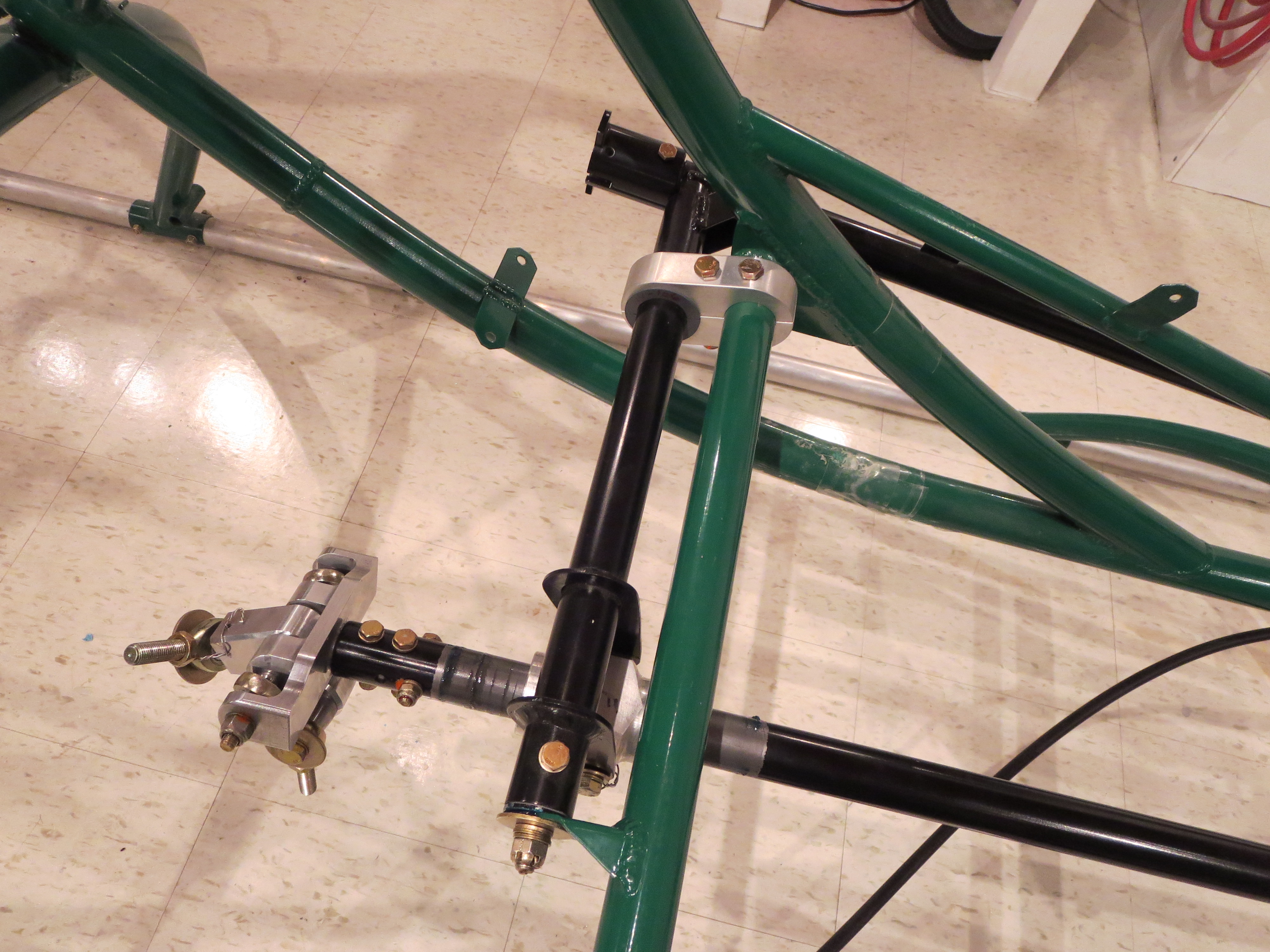
Top view of mixer and rods.
Bottom view of mixer. Lots more washers than really needed so I don’t bite into nylon on any of the lock nuts.
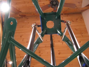
Looking up at walking beams. Obviously they are not set to the proper angle yet.
This is a clearance issue with the stick full forward - actually it limits the stick from going full forward. You can see the fore-aft rod end touching the mixer bracket. I could grind a little off the mixer, but I am going to wait until things are closer to being in rig to worry about clearances. The main thing is that it all fits and there is little or no slop at all in the controls and they all move cleanly. Very cool to see this come together. There is almost no friction in the system and BJ seems to indicate that a little friction is a good thing, so I will go back and reinvestigate.
Of course now it all comes back apart.
With the preliminary placement I can see the extent of the travel on the slider. Now I can go back and clean up and paint the cyclic control tube.
I just have one support call to make to Eagle, which will be my first. The mixer U-shaped aluminum wings are held together with an AN4 bolt (which looks to be a change from the machined bolt in the videos). Two washers are supplied - presumably one for under the head of the bolt and one for under the castellated nut. Well, with a washer under the nut there is not enough clearance for the rod end to move. Without the washer the nut rides right on the aluminum of the “wing”. That doesn’t seem right. Hmmm...
Cyclic Update
04/11/11 21:15 Filed in: All
4/11/2011 Update: I received the “Close Tolerance” bolts from Aircraft Spruce and they are cool. The diameter is only a few mils larger than the AN equivalent. In my case I could feel a little side-side where the cyclic stick to casting bolt felt a touch loose. With the Close Tolerance bolt there is no play and I have to tap the bolt in with a screwdriver base to get it in. Nice. No re-drilling or bolt upsizing required. I am keeping an assortment of these sizes on hand for just such occurrences.
No major building activity this week due to work/travel/taxes.
No major building activity this week due to work/travel/taxes.
Cyclic Controls
03/26/11 18:27 Filed in: All
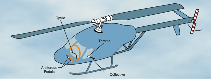
The Cyclic Controls direct fore/aft and lateral changes in force applied to the motion of the helicopter. This is probably the most complex part of the Helicycle design and as I have started to build it I am gaining appreciation for the elegant simplicity of the design employed. It’s hard to envision how it works together from pictures until you hold the parts in your hand and see the complex mixing of inputs performed. The cyclic control inputs and collective control inputs have to get mixed together before being applied to the direct rotor head controls.
Precise and careful manufacture of these subsystems will be undertaken to result in a smooth, slop-free response to operator input.
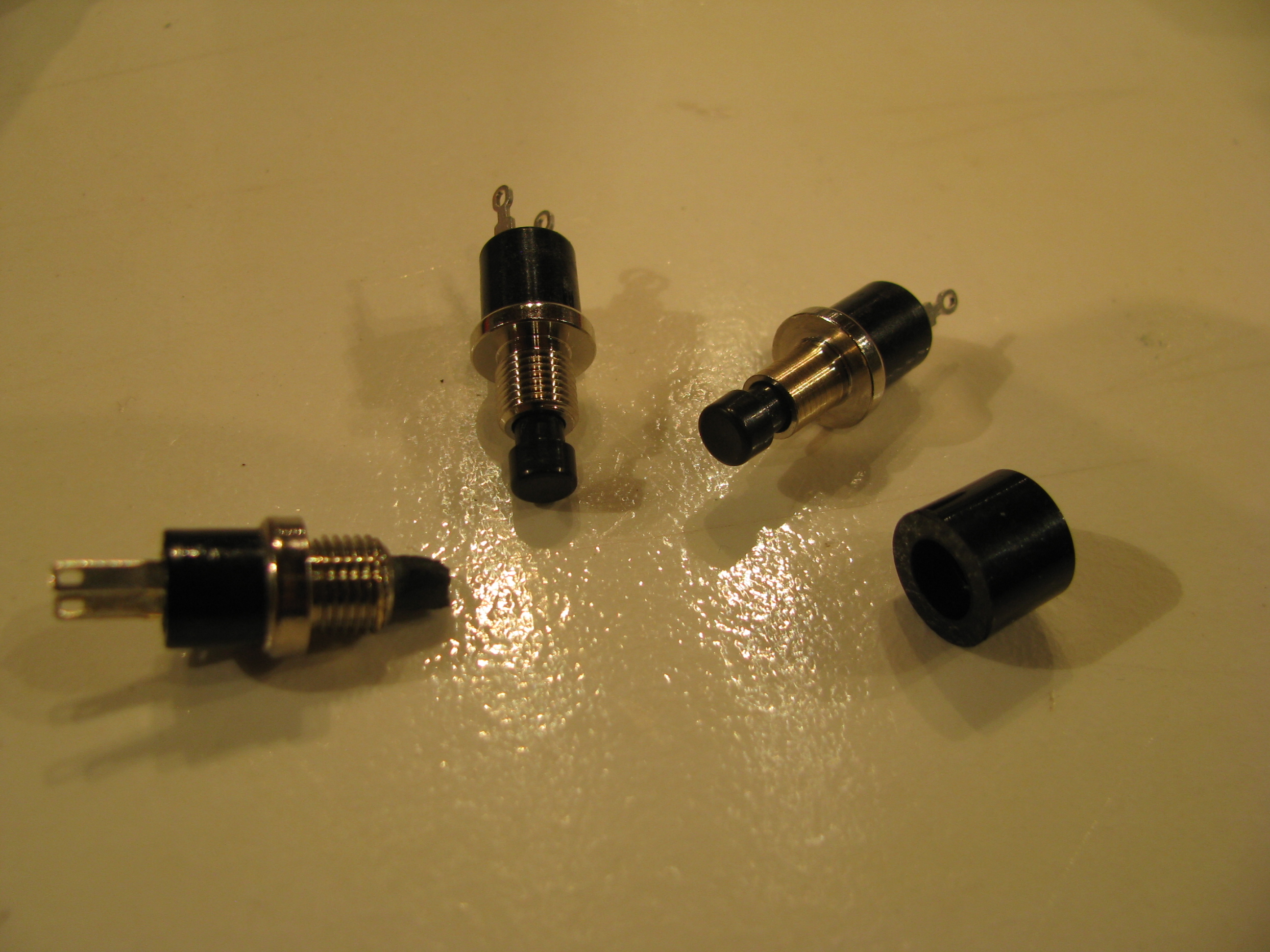
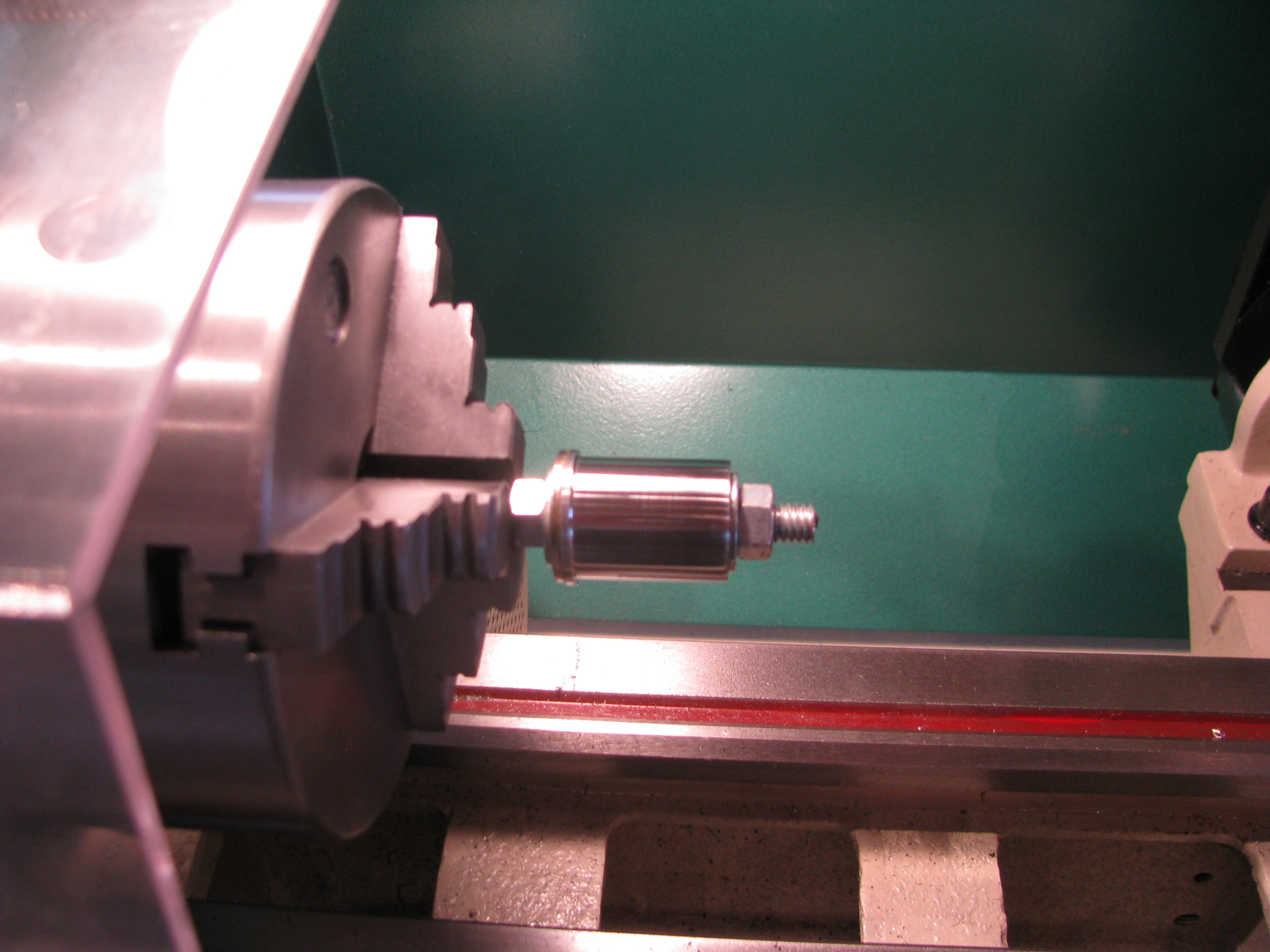
Of course having said that, the first thing I did was to break off the head of the Mic switch while trial fitting it to the handgrip. I got a couple of closest match replacements from Digikey (there are no visible vendor markings on the switch from the kit). The button head did not slide over the threads of the new switches, so I just lathed off the threads. The button head will get epoxied to the end of the new button switch.
Several hours shot finding replacements and reworking something that should have been quick.
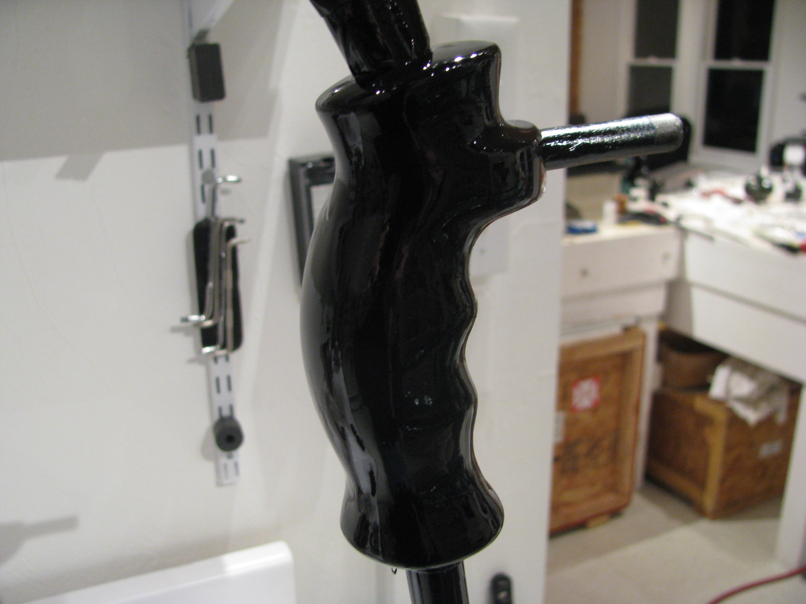
The grip provided seems fine for me. I know a lot of folks have replaced this with something more advanced, but using the top button for flip/flop on the radio, and the trigger for the Mic should be adequate for me.
Gotta remember to keep it simple or I will be building forever.
Some sanding and smoothing is required as the grip appears to be rough cast of an epoxy resin, then 6 coats of the VHT epoxy paint hopefully will prove durable.

Cyclic stick drilled to the casting. I must say that I am amazed just how many custom castings are included in this kit.
Another mistake. The bolt fit is kind of sloppy here, like the hole is maybe 1/64 too big. I don’t know whether I grabbed the wrong bit, or didn’t have the casting clamped well enough while drilling. I will first try a “close fit” aircraft bolt and then decide whether to bump up to an AN4 bolt.
Too bad, though. The hole is nice and square and centered. It’s always something.
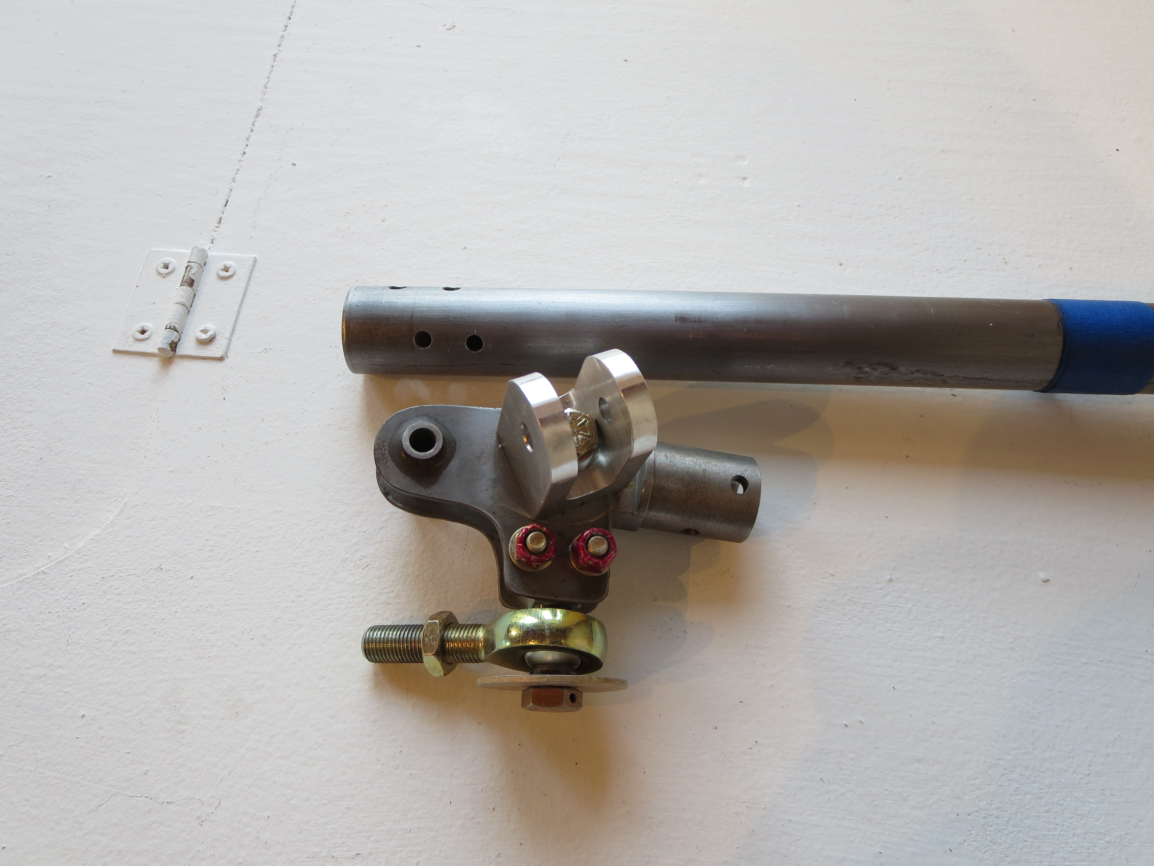
The steel plug for the front cyclic control tube was about 5-10 mils too large. Chucked it in the lathe and sanded it down a touch until it was very just very snug.
Had to sand the interior of the tube where the travel limit bracket was welded on. There were a few bumps where the tube deformed slightly while welding. Now the fit is snug, requiring just a light tap with a screwdriver handle to fit. Then I drilled the keeper bolt. Again, the mill/drill allows for a nice clean, square hole.
Cut 3/8 off the rod end and cleaned up the threads. The inner bush on the 5/16 rod end is very tight, even with additional grease. I may order some others if I can not get it to loosen up.
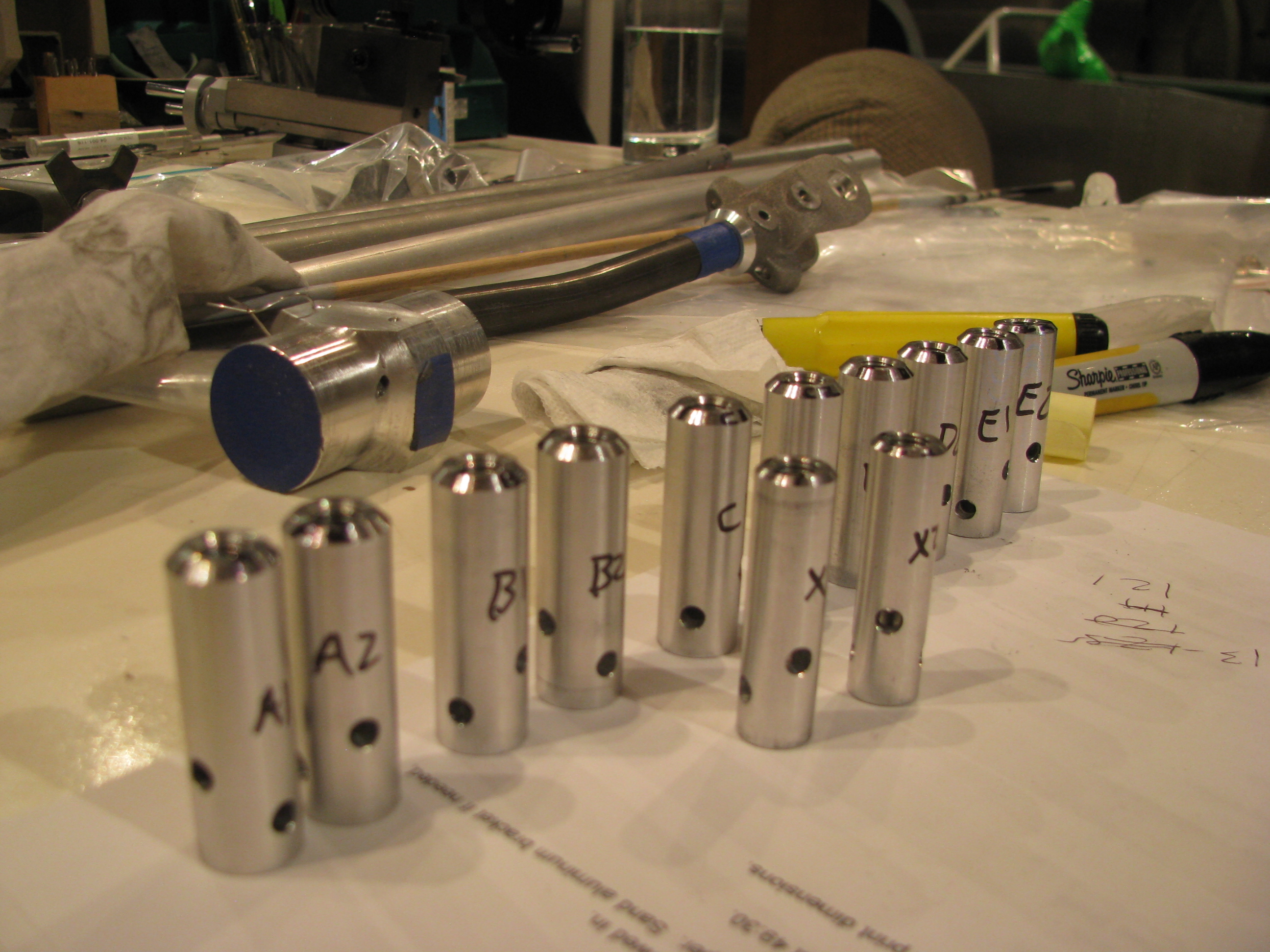
I agonized over how to make the holes for the safety wire/spring attach holes on the collective slider. After conjuring up many Rube Goldberg mill clamps, I ended up just free-handing it with a hand drill.
It’s a whacky angle since you definitely want to miss the interior features of the slider, but want the holes to pass through plenty of “meat” on the slider to stay strong. In both cases I was within 1/16 of my planned exit hole while drilling. Not bad. Start very small and work up very gradually, “steering” the smallest bit on the first cut.
Trial fit-up of the mixer assembly. Neat little assembly. Sanding and grease really do affect the feel, so follow the tapes closely.
My kit was different than the tape and the plans in that there is an AN4 bolt between the U-shaped wings instead of the machined allen bolt that BJ refers to. It was in the correct bag and fits properly, so I am assuming this has been updated since then.
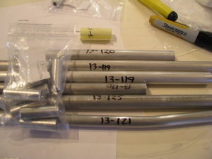
As a diversion, before drilling the mixer to the cyclic tube, I decided to knock off the control rod fabrication. I don’t know whether the kit came this way, or I did it to myself when we moved, but the rods were all taped together with cheap packing tape that left glue all over the rods.
It took about an hour with Goof-Off to clean them all up. That stuff was persistent. Goof-Off got its name because it will make you goofy if you breathe too much of it.
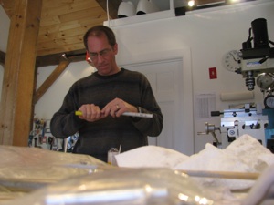
Obligatory, FAA-mandated picture of me deburring control rods. I engineered the shop lighting to highlight encroaching baldness. Works pretty well, eh?
This was another one of those jobs that looks really quick, but took all afternoon and evening to clean up the rods, fit and drill the control rod end plugs into the rods.
Perhaps I was being overly anal about perfect 90 degree angles between the bolts, but that’s always been very visible to me and an indicator about the quality that may exist elsewhere on the ship. I did notice that even BJ’s bolts are not all perpendicular to each other on the construction videos.
I think it was Tim Drnec’s site showing how he welded the plugs and ground the rods so no bolts were visible at all. That’s really cool and I am sure it looks great, but a little over-the-top. I’ll live with the bolts. It’s my mantra now: “Follow the plans and finish the project. Modify later.”
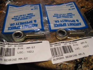
Not satisfied with the freedom of the end bearings I purchased another set from Aircraft Spruce. One is the teflon race insert (type T) and the other is the plain copper insert. The plastic insert rod end is as stiff as the the one supplied by the kit. The copper insert is as smooth as butter.
I am going to replace the ones in the kit (teflon insert) with plain copper inserts for smoothness of motion. Of course the ones I got were wrong. They are MM-5 and MM-5T. BJ uses XM-5 rod ends, which are heavier duty and larger. Crazy non-intuitive numbering system. The XM versions are not available at A.S. I had to order them from Wicks. The only possible downsides might be that the metal on metal requires periodic lubrication and might possibly cause some RF interference, but seeing as he used non-teflon rod-ends for all the smaller ones this can’t be a problem.