
2013
Hap Miller Bits
11/11/13 21:45 Filed in: All
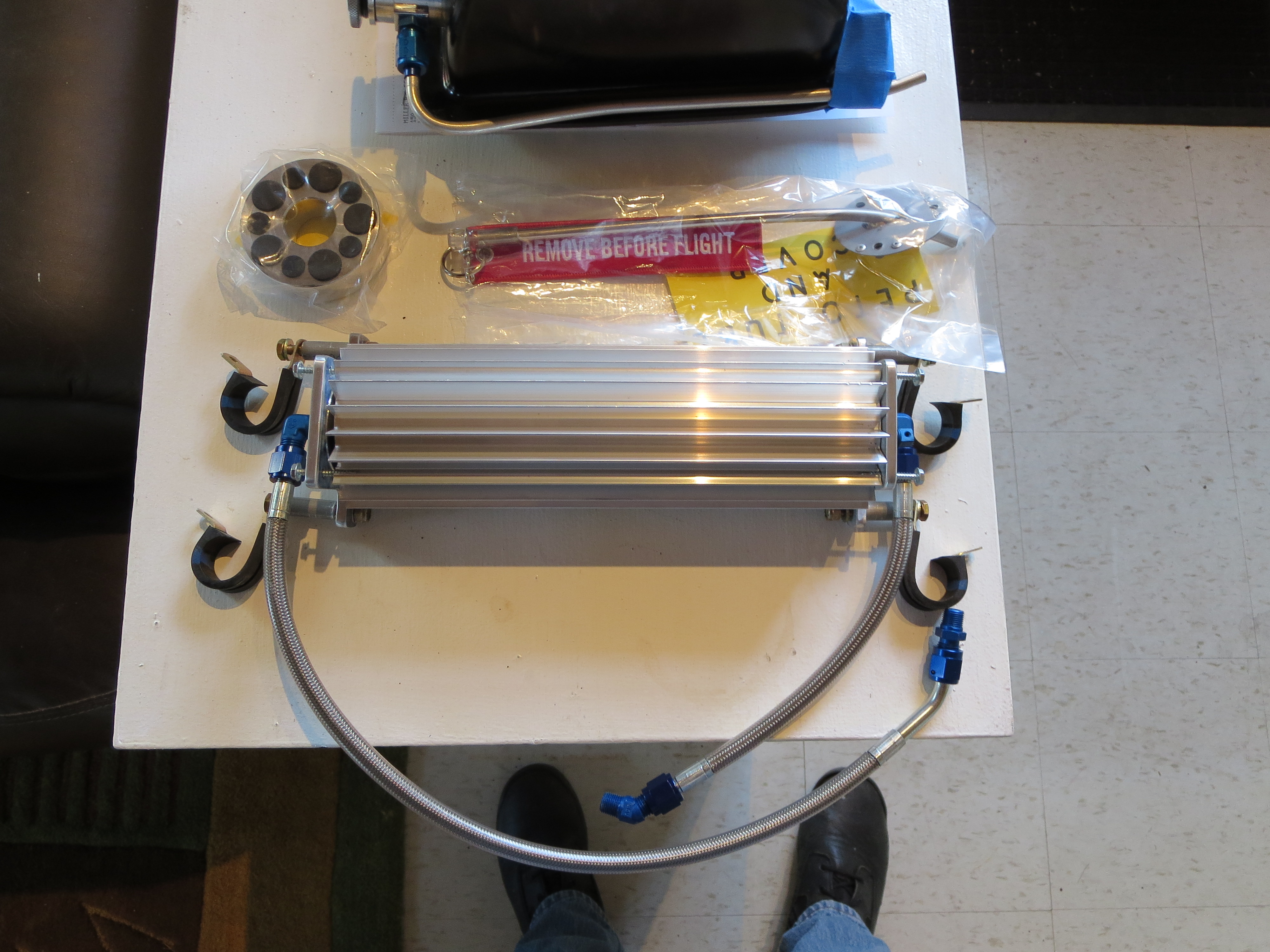
I ordered a bunch of bits and pieces from Hap Miller. Earlier I ordered and received his machined lift strut and it was of very good quality, so I wanted to see what else he has. Turs out a lot.
Here is the transmission oil cooler, clutch disk, and welded pitot tube. Nice!
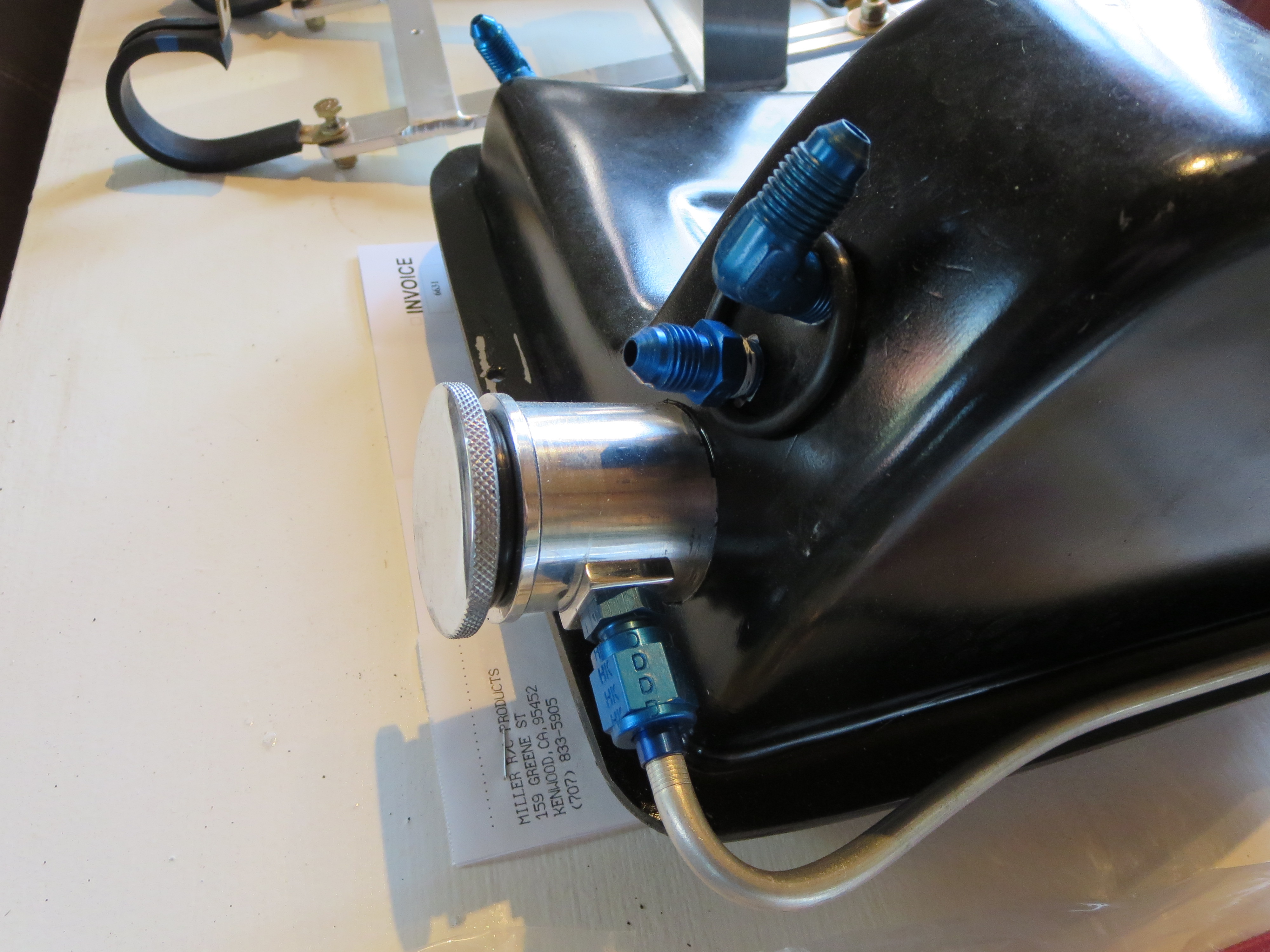
Hap claims that the "T" on the oil return to the tank actually impeded the return oil flow, so he recommends second fitting to return the oil independently and will add one to your tank. He also has a nice machined cap with integral dipstick.
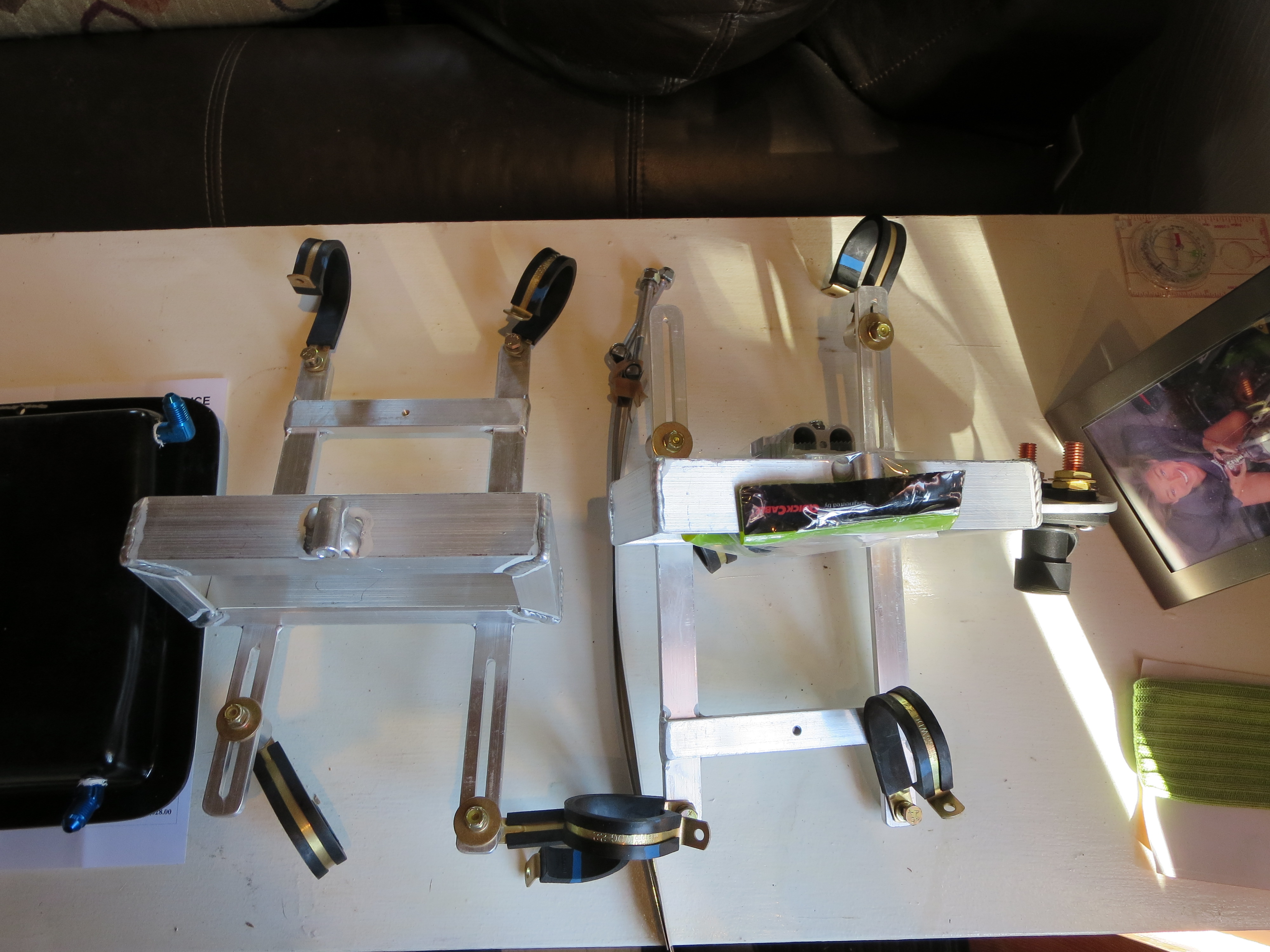
Lastly are the battery boxes. These mount just behind the transmission and accommodate a pair of Odyssey PC680 batteries. Nice aluminum welding work. It will be a shame to paint them and cover up those nice beads.
Fin Painting
11/02/13 17:48 Filed in: All
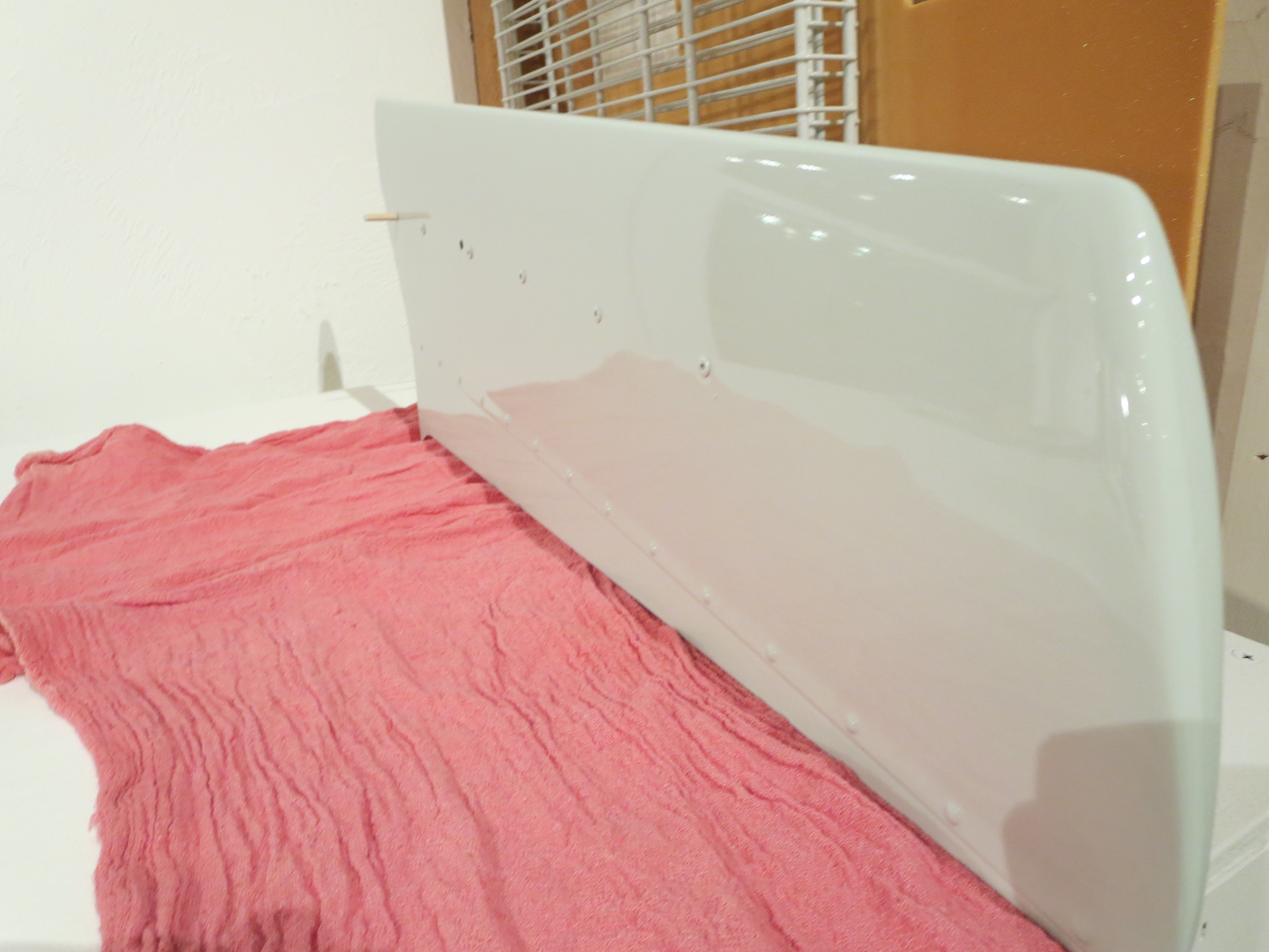
The first “real” parts painted were the fins. This is Eastwood single-stage urethane. I first practiced on a couple sheets of aluminum I had in the shop, and good thing. There was a fair amount of fiddling with the gun and the first one was a mess.
Keeping the piece flat and getting the second and third coat relatively heavily allowed for a nice flow out. Very smooth. A little orange peel. Not much.
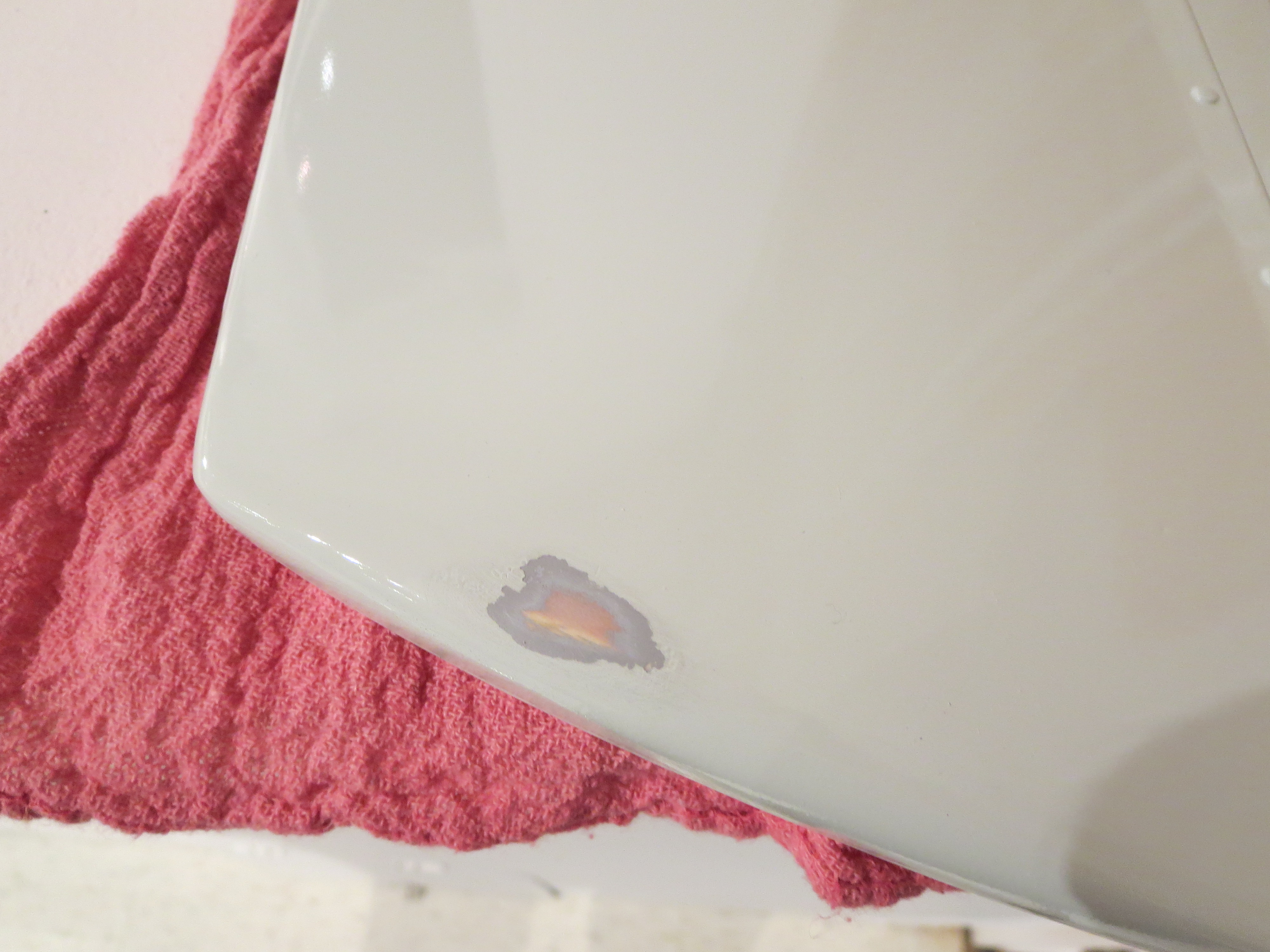
My one flaw is on the underside of the horizontal fin. The Fin slipped down the jig on which I had it and stuck to the piece of MDF I had underneath it. I will have to scuff this and repaint this side.
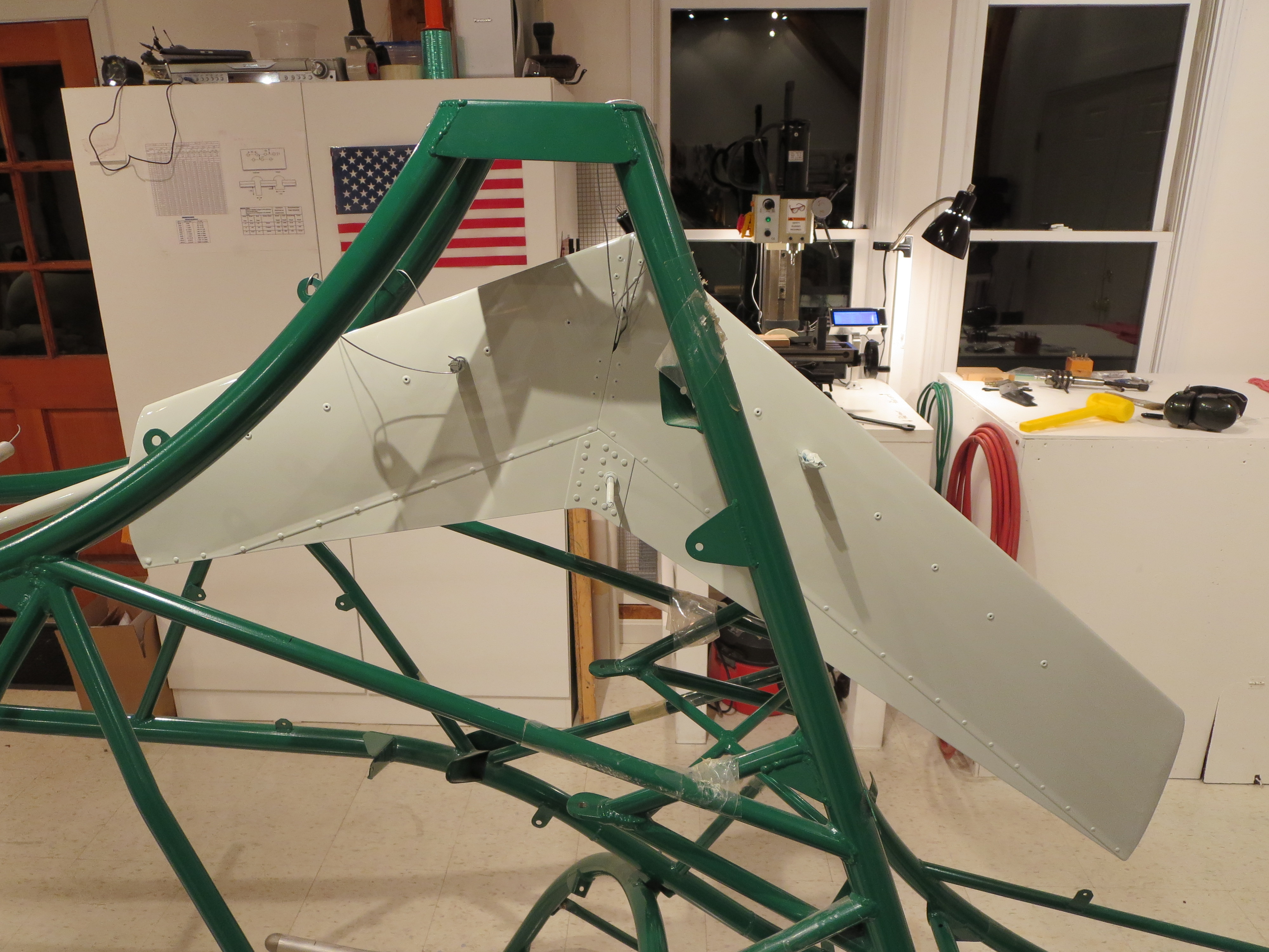
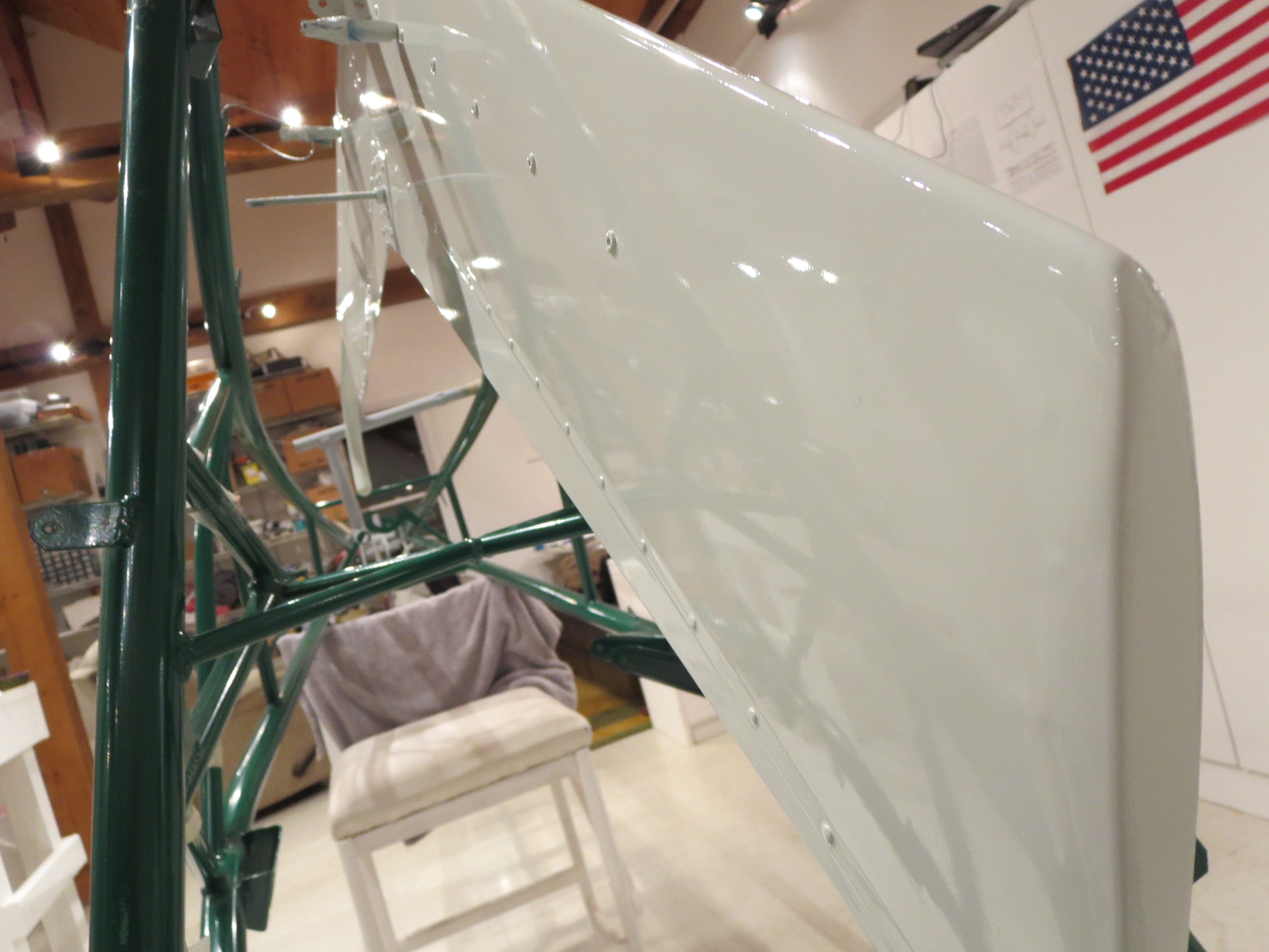

This is the vertical fin. Overall I am happy with the result. The only issue is that the Eastwood “Bright White” is not nearly as “bright” as I would have thought. It is slightly more grey than absolute white. I am getting used to it, though.
Now that the fin is painted I can select an N-Number and affix it to the fin. Progress.
Ground Plane Paint
10/29/13 17:46 Filed in: All
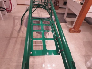
For the structural parts I bought some enamel paint that matched the frame powder coating. This is the ground plane for the comm antenna.
Pre-Wiring
10/29/13 17:30 Filed in: All
Starting in on the wiring of the panel. Have practiced crimping and roughly mapped out the wiring pathways. Power on one side of the avionics stack and a large 37 pin DSUB for all the signals that leave the panel on the other side.
Instrument Fitting
08/17/13 17:27 Filed in: All
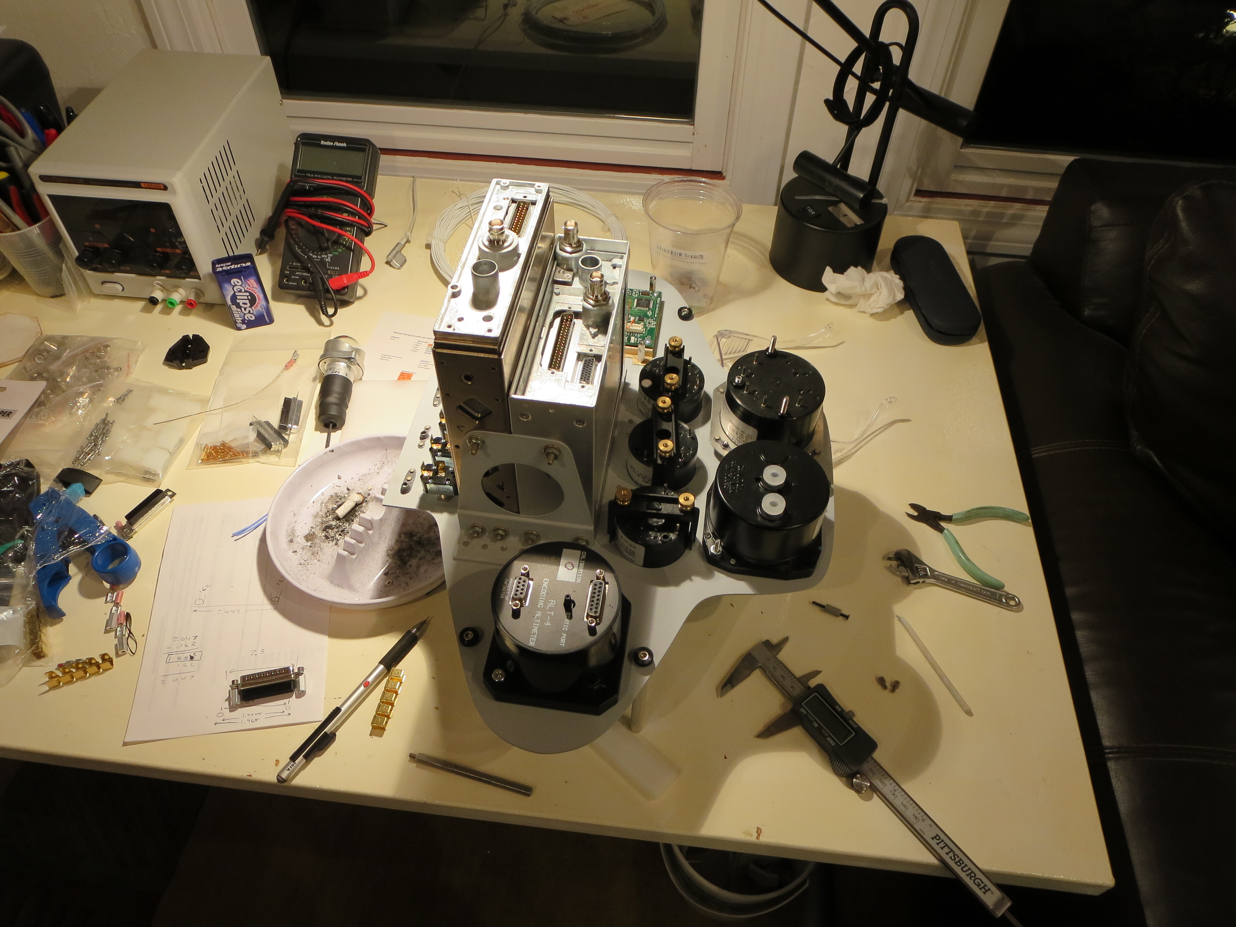
Started by lathing up and tapping some struts to elevate the panel while fitting gauges. Having the lathe and mill always set up allows me to quickly bang out these pieces which facilitates the work.

Gauge holes trimmed up and gauges fitted. I decided to fit the large gauges behind the panel just to improve the symmetry and improve the look. The square gauge on the right is my homemade digital compass.
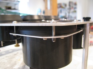
To flush mount the tach, I made this little plate to capture the gauge behind the panel. It’s really flat and parallel in spite of the camera distortion.
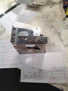
I am really digging having the mill with DROs. Made up a little sketch of the angles to mount the trays from the Garmin specs, measured and drilled and everything fit. The digital readouts make this operation a cinch. Also, the tolerances achievable are amazing.
Freehand, this would have required a bunch of fiddling and tweaking to get to fit. With the precision of the machine tools it basically falls together.
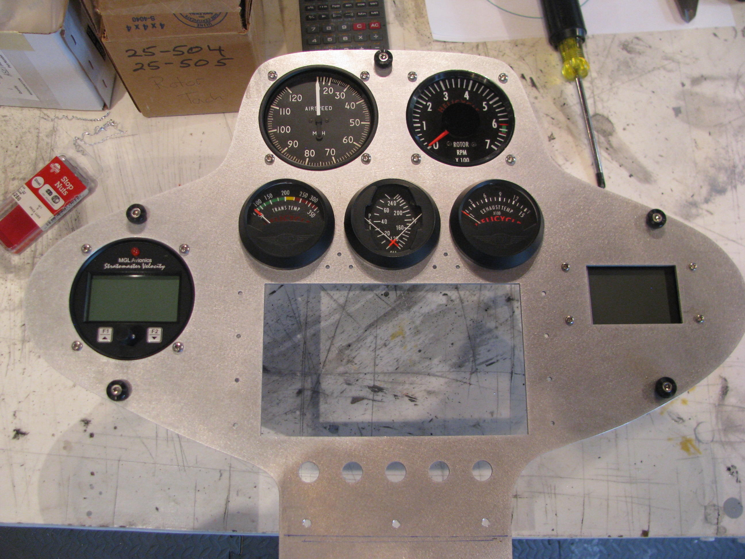
Gauge holes trimmed up and gauges fitted. I decided to fit the large gauges behind the panel just to improve the symmetry and improve the look. The square gauge on the right is my homemade digital compass.

To flush mount the tach, I made this little plate to capture the gauge behind the panel. It’s really flat and parallel in spite of the camera distortion.
I am really digging having the mill with DROs. Made up a little sketch of the angles to mount the trays from the Garmin specs, measured and drilled and everything fit. The digital readouts make this operation a cinch. Also, the tolerances achievable are amazing.
Freehand, this would have required a bunch of fiddling and tweaking to get to fit. With the precision of the machine tools it basically falls together.
Mill DRO Design & Build
07/12/13 18:43 Filed in: All
Clearly an accurate digital readout of the X, Y and Z-positions of the table and mill head will make jobs go much faster.
I purchased 2x12” and 1x8” digital caliper mechanisms off eBay for $24 for the 12” and $18 for the 8” respectively. I have read about various folks interfacing to those and hooked the interface signals up to a scope and observed and played around until I figured out exactly the protocol coming over the interface ports from the calipers.
For the ones I purchased the protocol seems slightly different than that measured by others. In my case the value output over the interface is simply a hex representation of the position in whatever units are selected (mm or in). One of the bits indicates the sign (it is not true twos complement), and another bit indicates the 0.0005” indication.
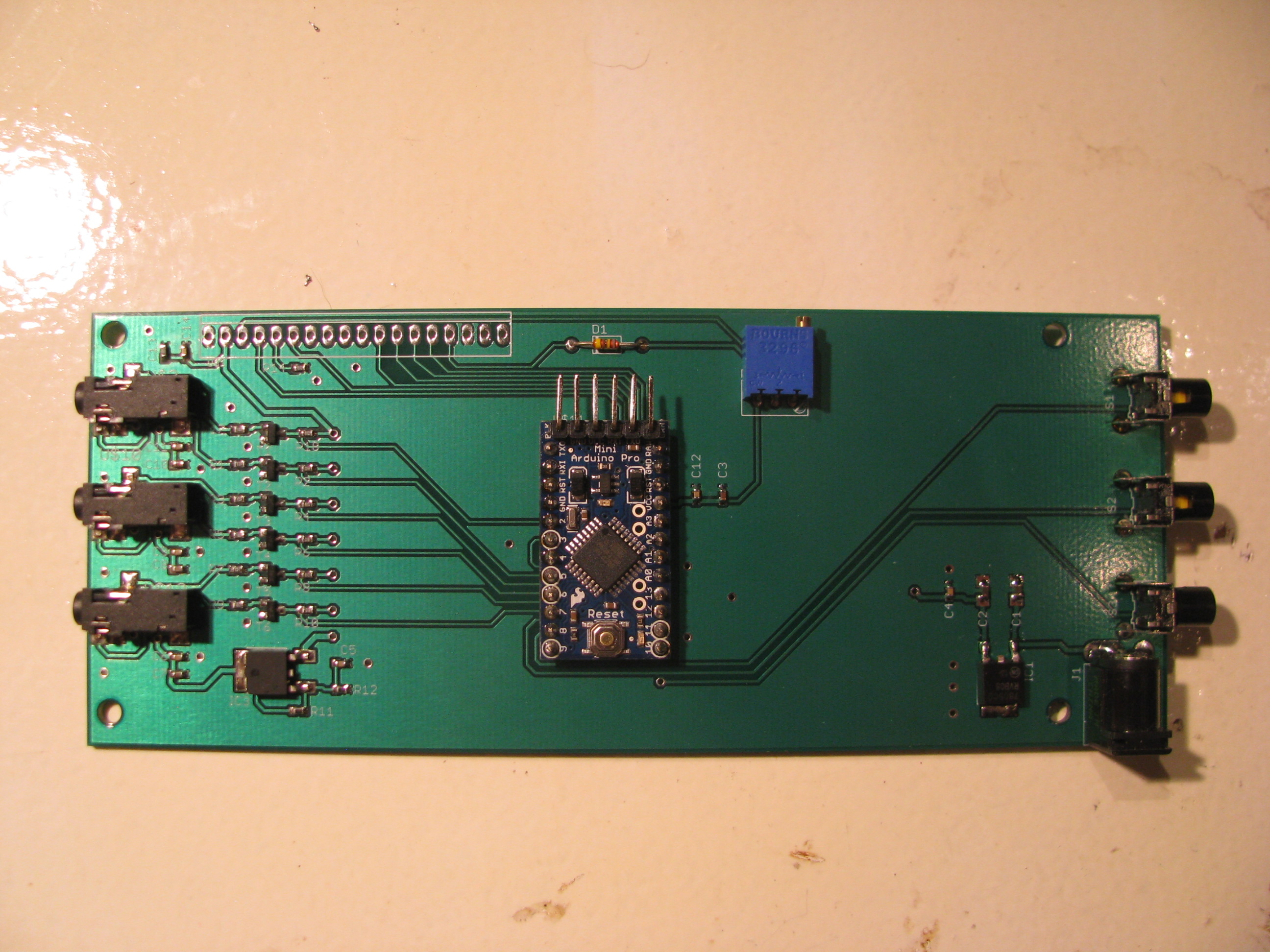
I whipped up a circuit to convert the voltage levels and wrote code to read the three values with an Arduino (that’s a ProMini in the center). I soldered the wires from 3 cellphone headsets (4-pin 3.5mm plugs with very, very fine flexible wires) to the caliper ports. The complete headsets were $0.99 each on eBay, which is cheaper than it would have been to buy connectors and cable and make my own. There’s $7 of buttons, connectors, passives, transistors, and regulators from Digikey rounding out the B.O.M.
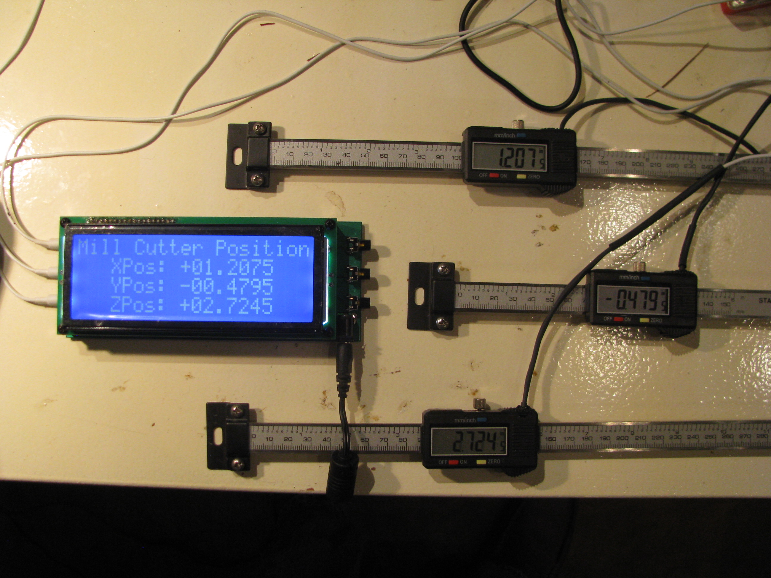
The crowning piece is a large-character 20x4 character LCD display also bought on eBay for $22.
I layed out a circuit and had it fabricated through Sunstone.com using their “Value Proto” service, which is relatively cheap. It’s mounted here behind the LCD. There are buttons on the right for zeroing out the reading on each axis independently for positioning on a workpiece.
The Arduino is clearly running at capacity to handle the three calipers worth of data. Each caliper has a clock and data line. The clock triggers an interrupt, which causes me to sample the data line on the respective port. Two of the clocks trigger the ATMega’s native pin interrupt functions and the third (Z-axis) triggers a pin change interrupt (which is a bit slower). About every 20 seconds or so one of the readings may glitch and a weird reading is indicated for one loop, probably because of a sampling error caused by the fact that the interrupts are happening right on top of each other, causing me to sample one reading incorrectly. It is so infrequent that it will not affect usage of the DRO.
Uber Weenie Alert!:
Here are the technical details of my DRO circuitry and Arduino code for my setup. If you have questions feel free to email me as the above descriptions are pretty terse:
DRO_SupportBD_sch.pdf
DRO_SupportBD_brd.pdf
DRO_Rev3.ino
LCD_Support.ino
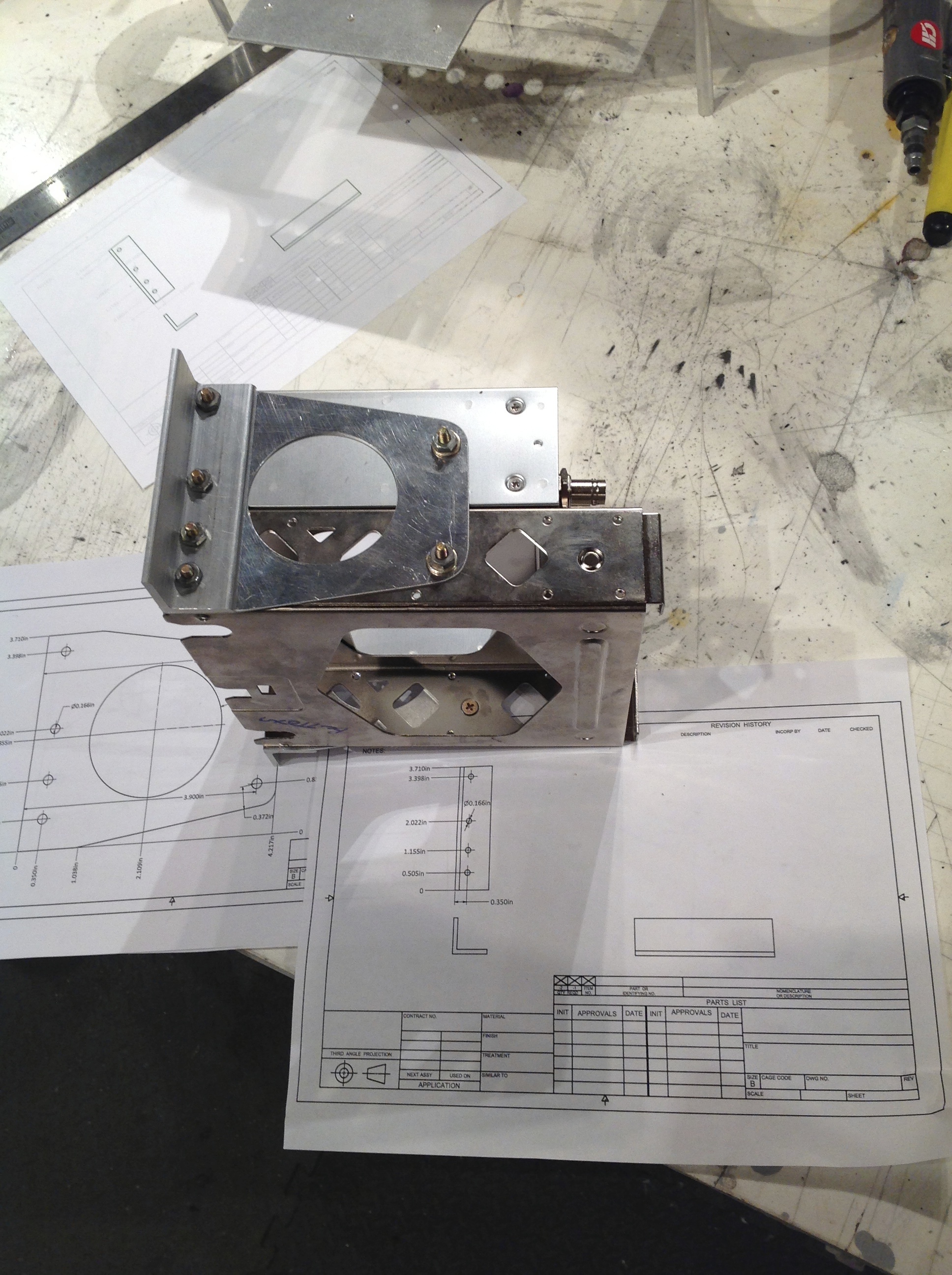
8/10/13 - DRO Mounting and Finishing of the Mill. I bought the FIgnoggle plans, and downloaded the free plans from the Little Machine Shop for mounting the DRO scales. Then I proceeded to ignore them both since they seemed overly complicated. They might make sense if you were trying to actually read the indicator on the scales themselves, but since I have my new big display, I found I could simplify the the mounting scheme to simple plates and spacers. The only tricky one was the 6degree wedge to vertically align the Y-axis mount with the base angle. No problem - I have a mill.
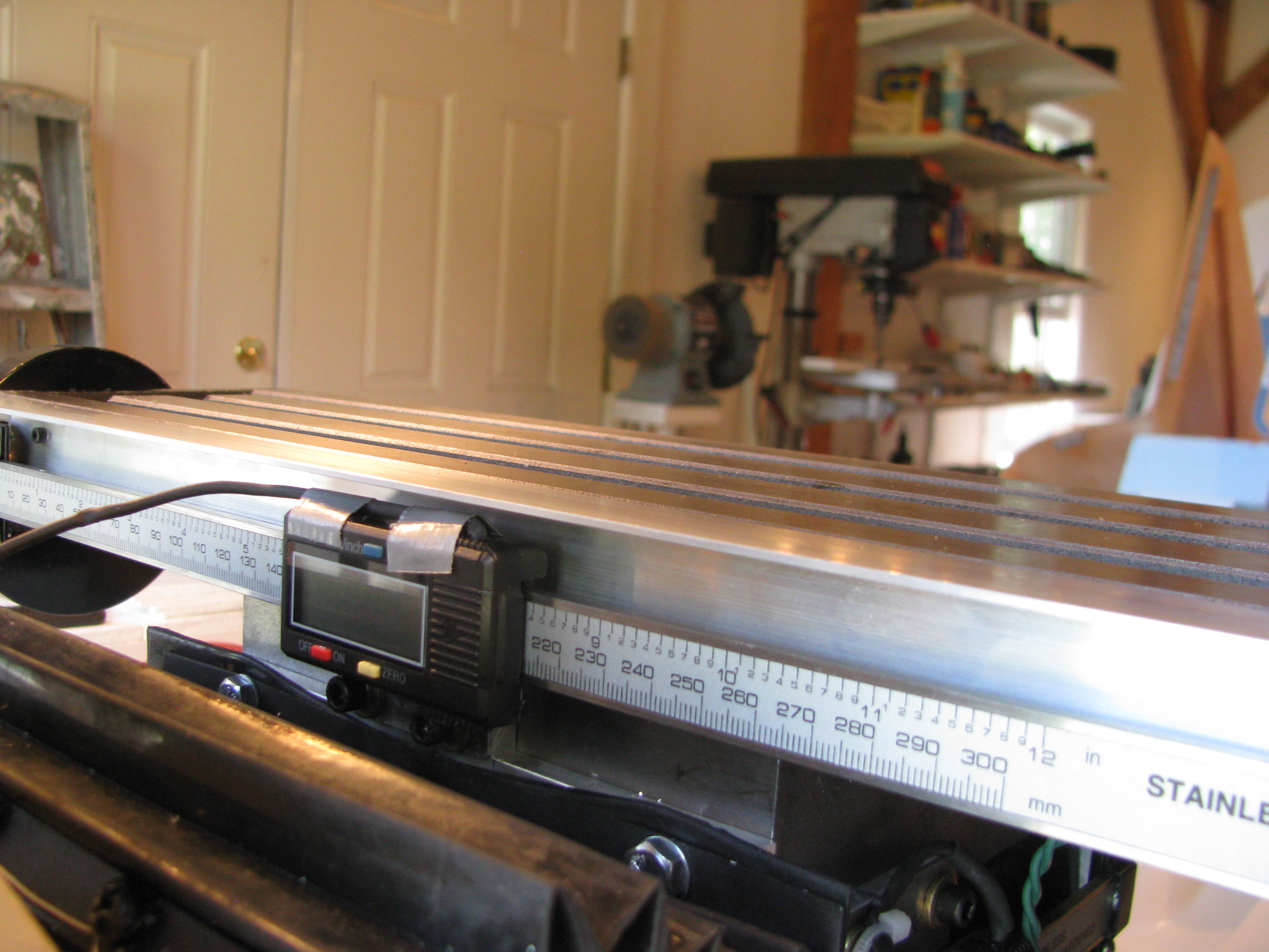
Y- Axis Mounting. The sliding part of the scale is mounted to the Y-axis carriage. An 0.040” plate is screwed into the caliper’s tapped holes, then 10-24 holes are drilled and tapped into the carriage (be careful - not to deep or you’ll hit the ways). There’s another 0.25” spacer behind those allen bolts, elevating the slider. The scale is fixed to the base using the supplied brackets and a wedge machined down from 0.25” plate. Just put an elongated slot in the wedge and you can slide it up or down until it is spaced properly.
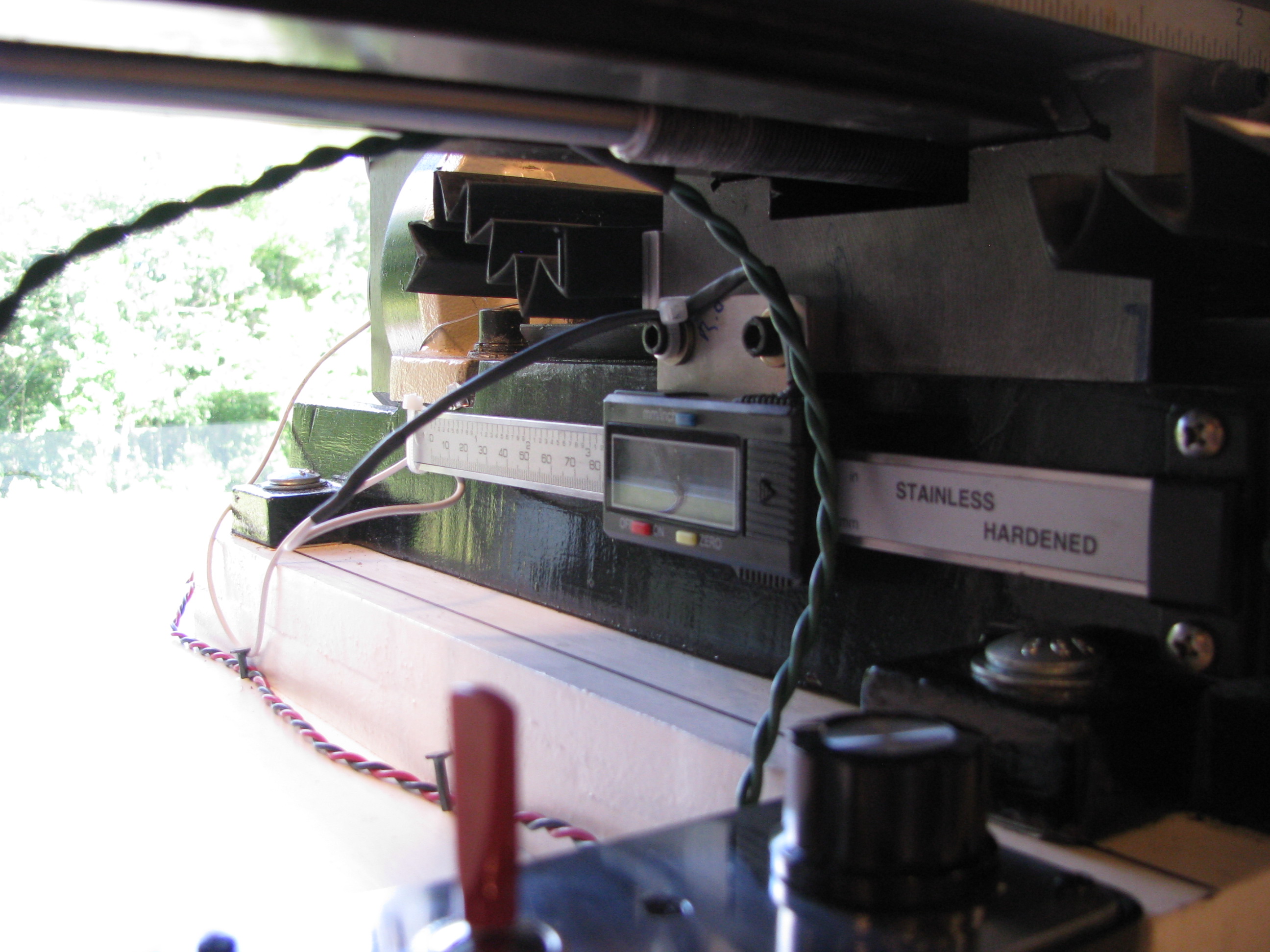
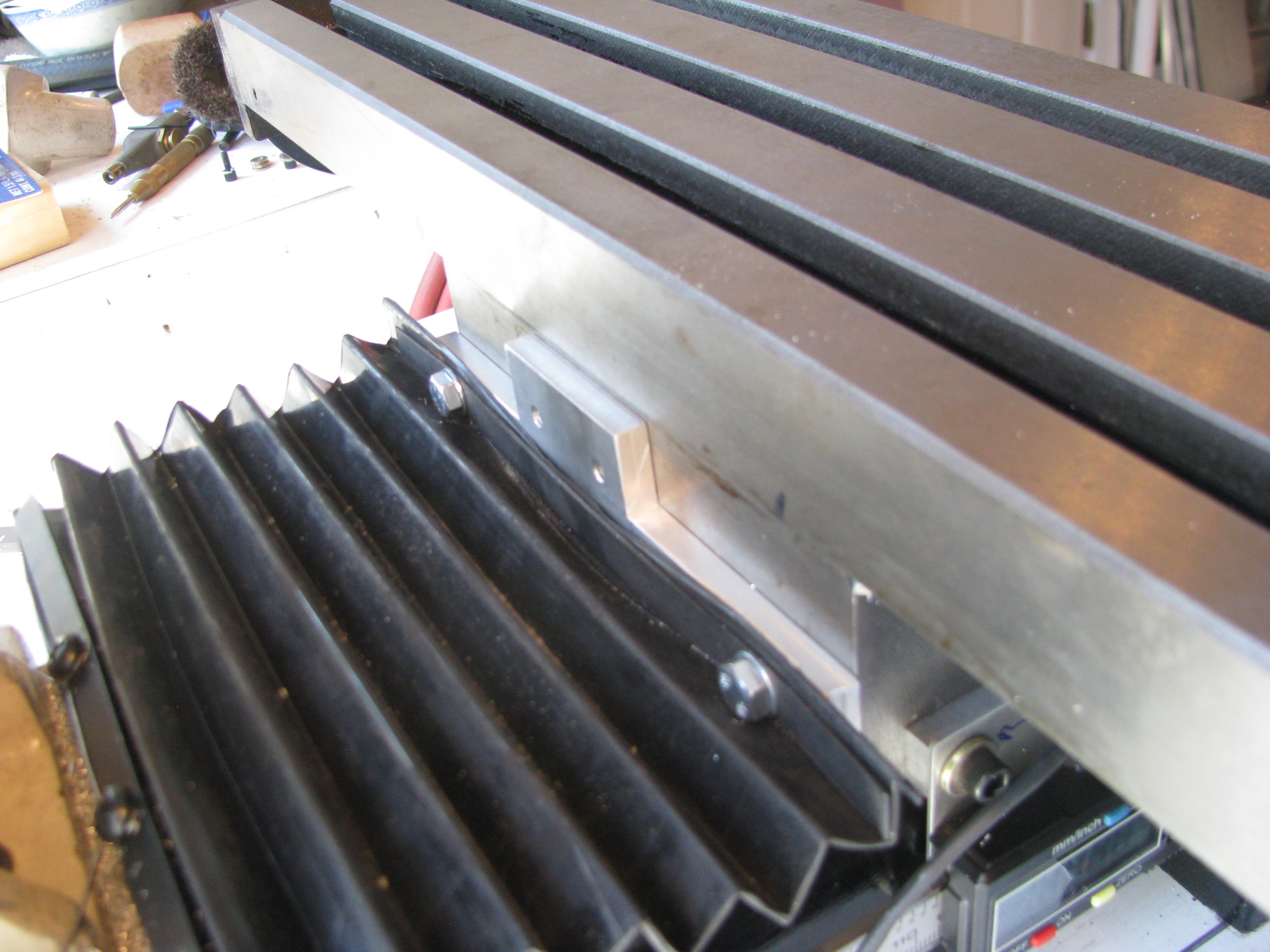
X-Axis mounting. I didn’t want the scale on the front since it would interfere with the Y-handle and the gib lock. The only tricky part was that there was no way I could drill from the back and I didn’t want to remove the column. I used the pre-existing holes for the rubber boot and machined a plate to mate with those pre-existing holes and allow for the slider plate no the caliper to screw into it. The scale is simply mounted to the table on one end. Only one hole is needed and washers (which I have many of and various thicknesses) to fix the scale to the table. The display is fixed to the Y-axis carriage, the scale is mounted ot the X-table. I then mounted a fixed angle to the table to cover and shield the scale.
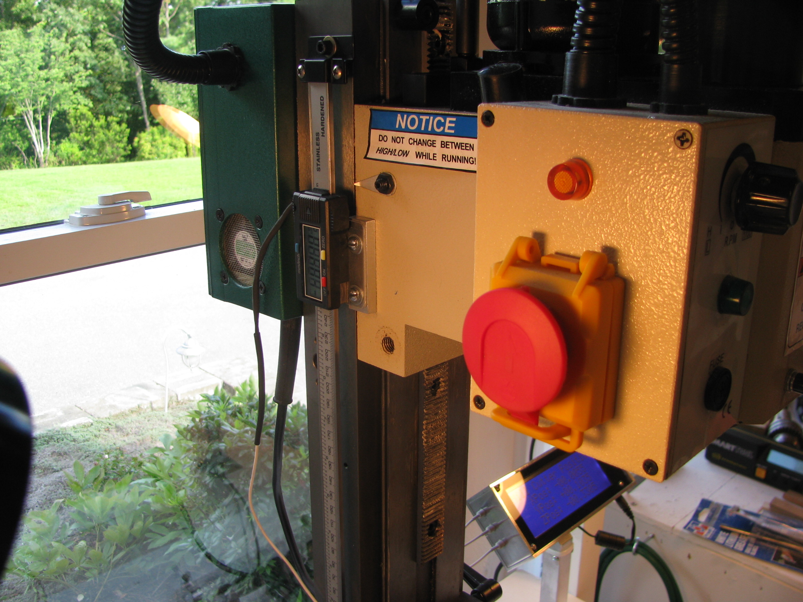
Z-Axis DRO Mount - I removed the existing visual scale (next to useless), as well as the existing spring support. This freed up a lot of room to mount the DRO scale.I just opened up and tapped on of the already existing holes on the column, and drilled two holes in the head casting for the slider. Again, an 0.040” plate on the caliper slider and a 0.25” spacer on the head casting. Simple. As before, be careful not to drill&tap too deep on the casting or you’ll hit the ways.
Other Mods - I purchased the Air Spring kit from Little Machine Shop. This provides two things; 1) A better spring, which is more linear and allows for greater travel of the head, and 2) a longer rack so that you can lower the head much closer to the table.

DONE DONE DONE! Now, a fully enhanced X2 class mini-mill. Extended travels on X, Y, and Z axes, a power feed, and DRO on all three axes. Nice to be completed and I learned a lot and practiced more machining technique.
Took the opportunity to scrub the shop from top to bottom and prep for the next project(s) now that this one is in the bag.
Mill Power Feed
07/08/13 18:39 Filed in: All
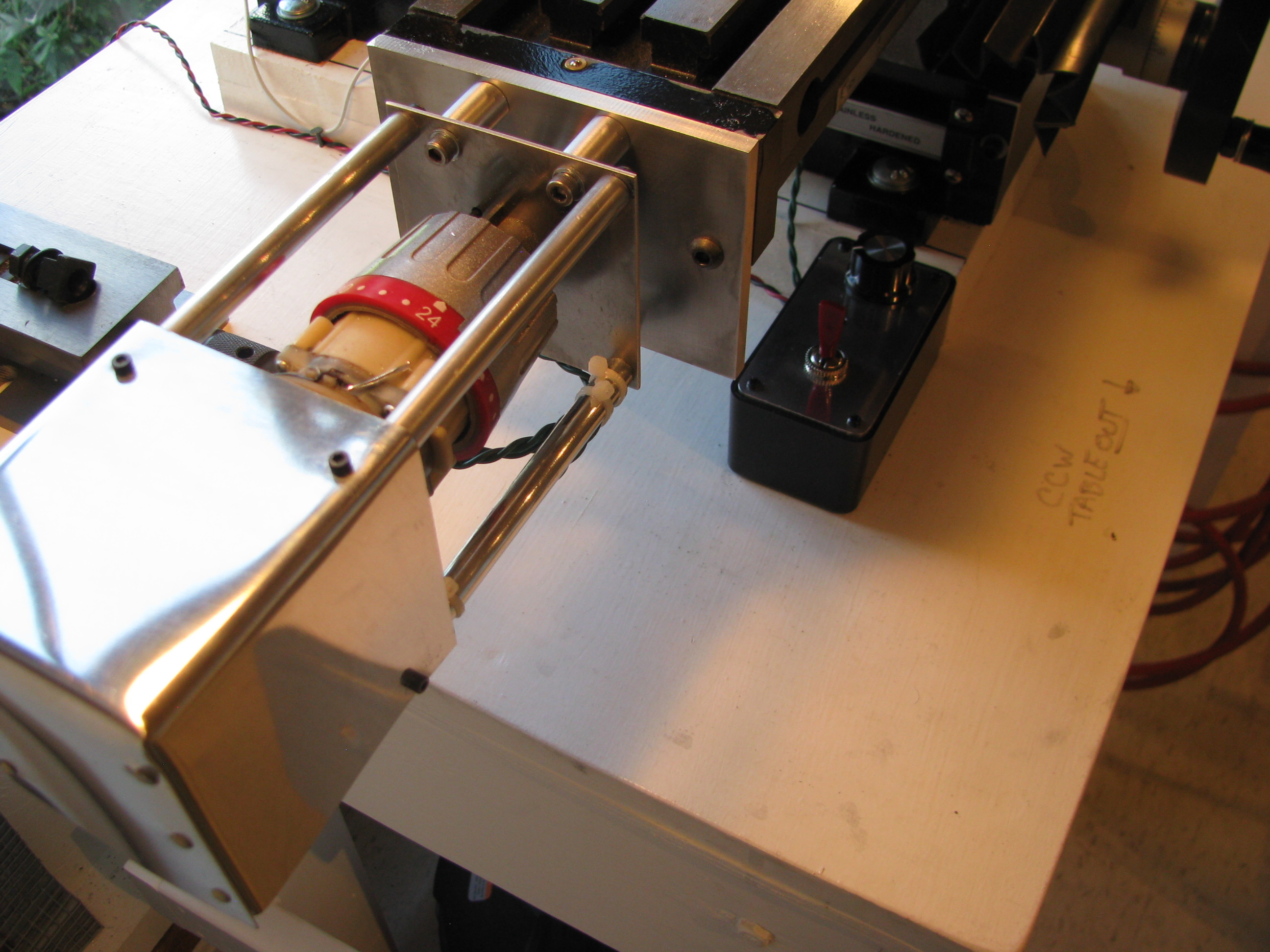
Power Feed. After milling for a bit it is pretty evident that a power feed is definitely a time and wrist saver. I had a cordless Harbor Freight Hammer Drill that I never liked all that much that served as a donor for the motor and gearbox. I stripped it down discarded the electronics and lathed off the notched ring that gave it the hammer action.
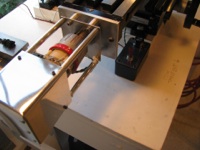
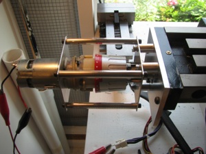 I used it as an exercise in machining to build a frame to hold the gearbox and make an adapter plate to fit the mill.
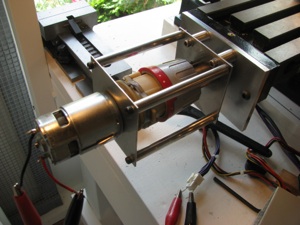
For airplane parts it is common practice to drill parts in assembly. In this case however, I made sketches and machined all the parts to spec, being careful on all the measurements. Even though not necessary, I was able to hold tolerances to +/- 0.001” on all dimensions. Not bad for a noob. Everything fit together with very tight tolerance and no play anywhere. Satisfying.

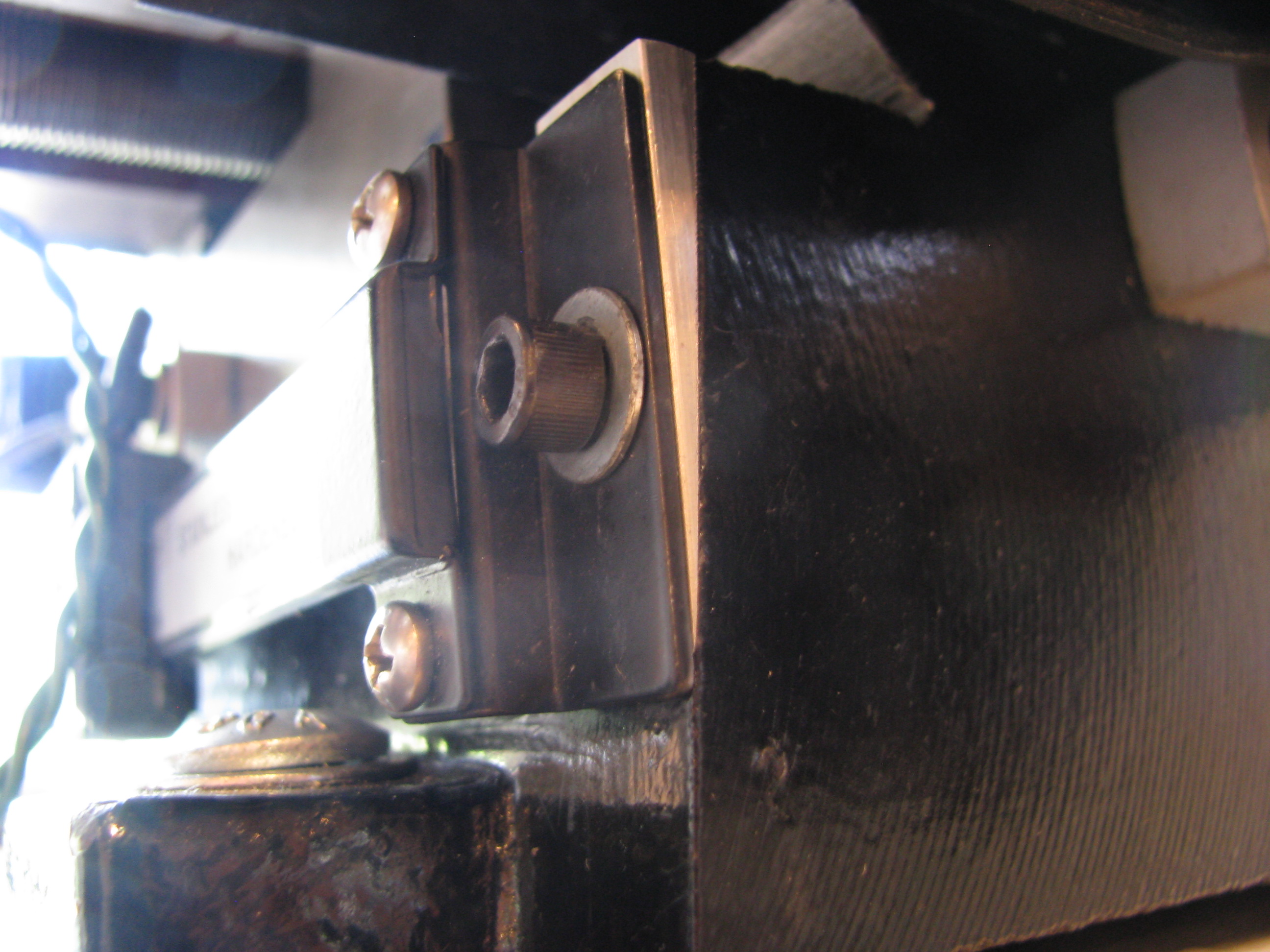
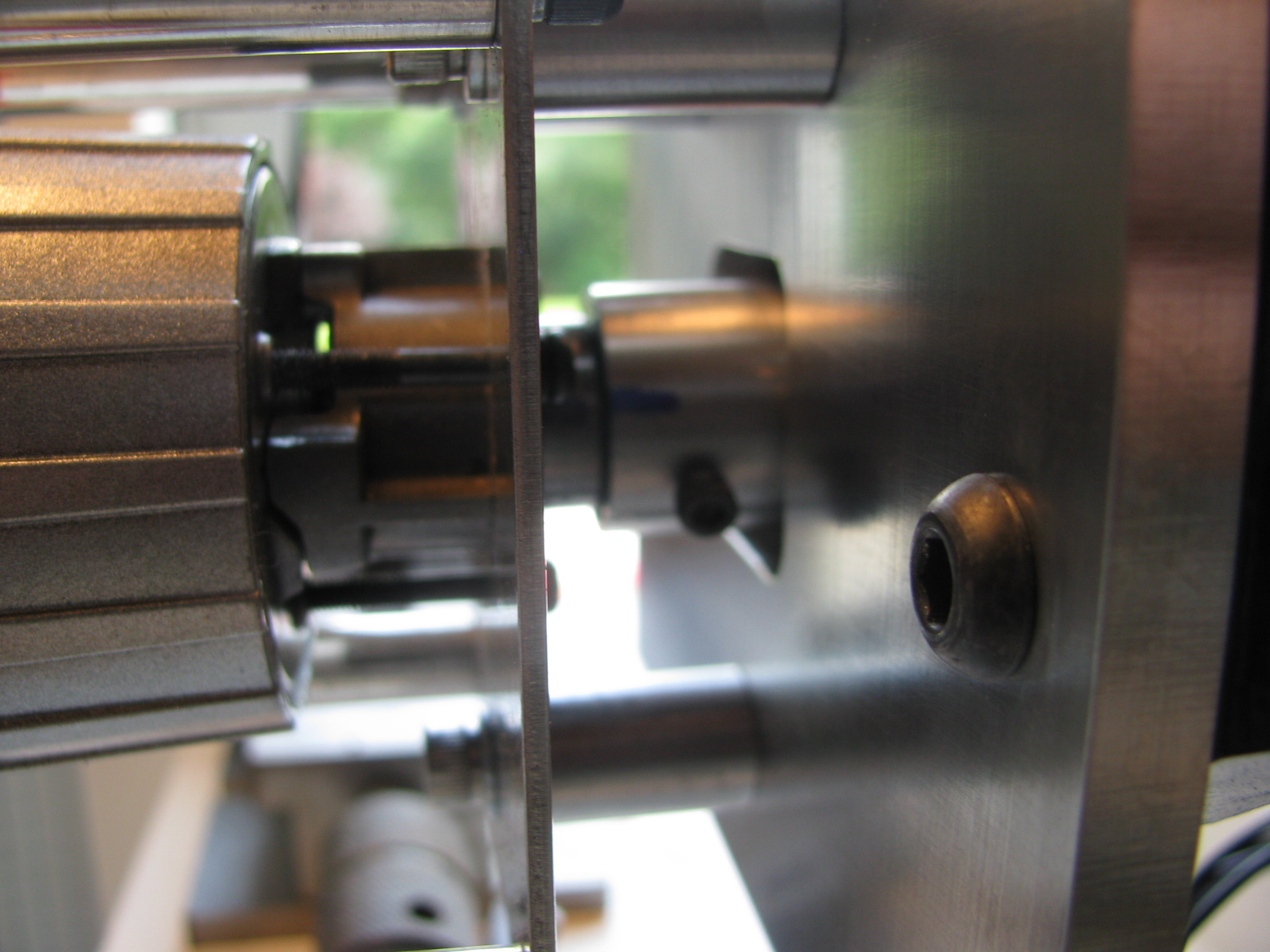
To link the drill shaft to the X-axis lead screw, I machined a coupler with a tongue that mates to a slot already present in the lead screw, and then drilled a hole through the coupler and drill shaft.
The coupler is threaded for a couple of 4-40 allen screws. When they are backed out the coupler spins freely on the drill shaft in case I want to machine without the power feed engaged. A little cumbersome and it it becomes a pain I will fit a quick-release pin instead of the screws.

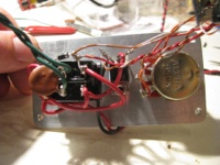
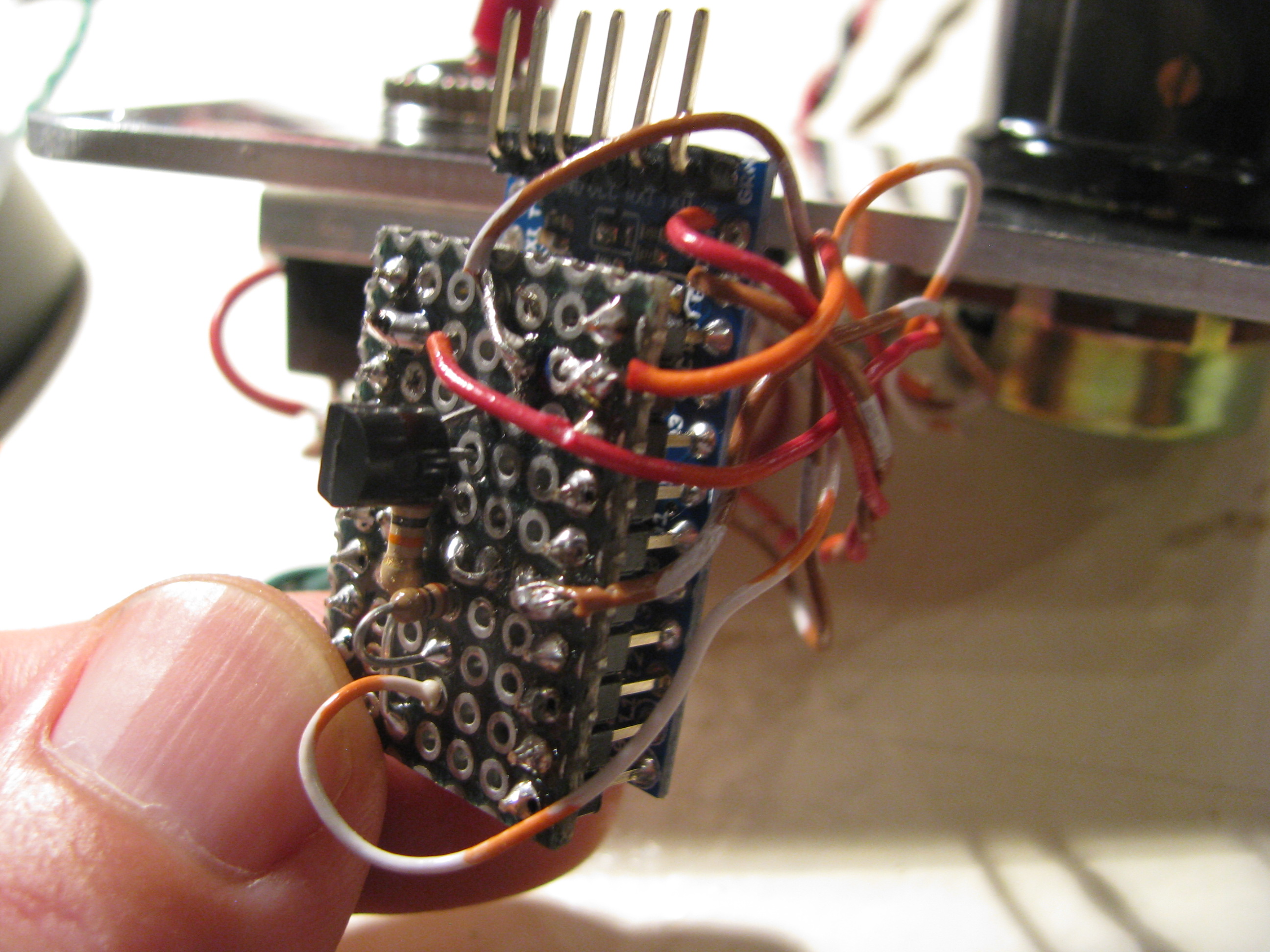
Speed Control for Power Feed. Being hooked up on the Arduino, I whipped up a little PWM program. It reads the voltage on a linear pot and adjusts a PWM signal output width. I just used a DPDT-Center Off switch to change direction and turn it off, so the Arduino’s job is simple. Just read a POT, adjust the PWM pulse width and drive a power FET (IRFZ44). A little Radio Shack Project box with the aluminum cover replaced with a 0.125” plate machined to accept the switch, POT, doubles as the heat sink for the FET as well. Works great.


For airplane parts it is common practice to drill parts in assembly. In this case however, I made sketches and machined all the parts to spec, being careful on all the measurements. Even though not necessary, I was able to hold tolerances to +/- 0.001” on all dimensions. Not bad for a noob. Everything fit together with very tight tolerance and no play anywhere. Satisfying.
To link the drill shaft to the X-axis lead screw, I machined a coupler with a tongue that mates to a slot already present in the lead screw, and then drilled a hole through the coupler and drill shaft.
The coupler is threaded for a couple of 4-40 allen screws. When they are backed out the coupler spins freely on the drill shaft in case I want to machine without the power feed engaged. A little cumbersome and it it becomes a pain I will fit a quick-release pin instead of the screws.

Speed Control for Power Feed. Being hooked up on the Arduino, I whipped up a little PWM program. It reads the voltage on a linear pot and adjusts a PWM signal output width. I just used a DPDT-Center Off switch to change direction and turn it off, so the Arduino’s job is simple. Just read a POT, adjust the PWM pulse width and drive a power FET (IRFZ44). A little Radio Shack Project box with the aluminum cover replaced with a 0.125” plate machined to accept the switch, POT, doubles as the heat sink for the FET as well. Works great.
Milling Machine
06/13/13 17:59 Filed in: All
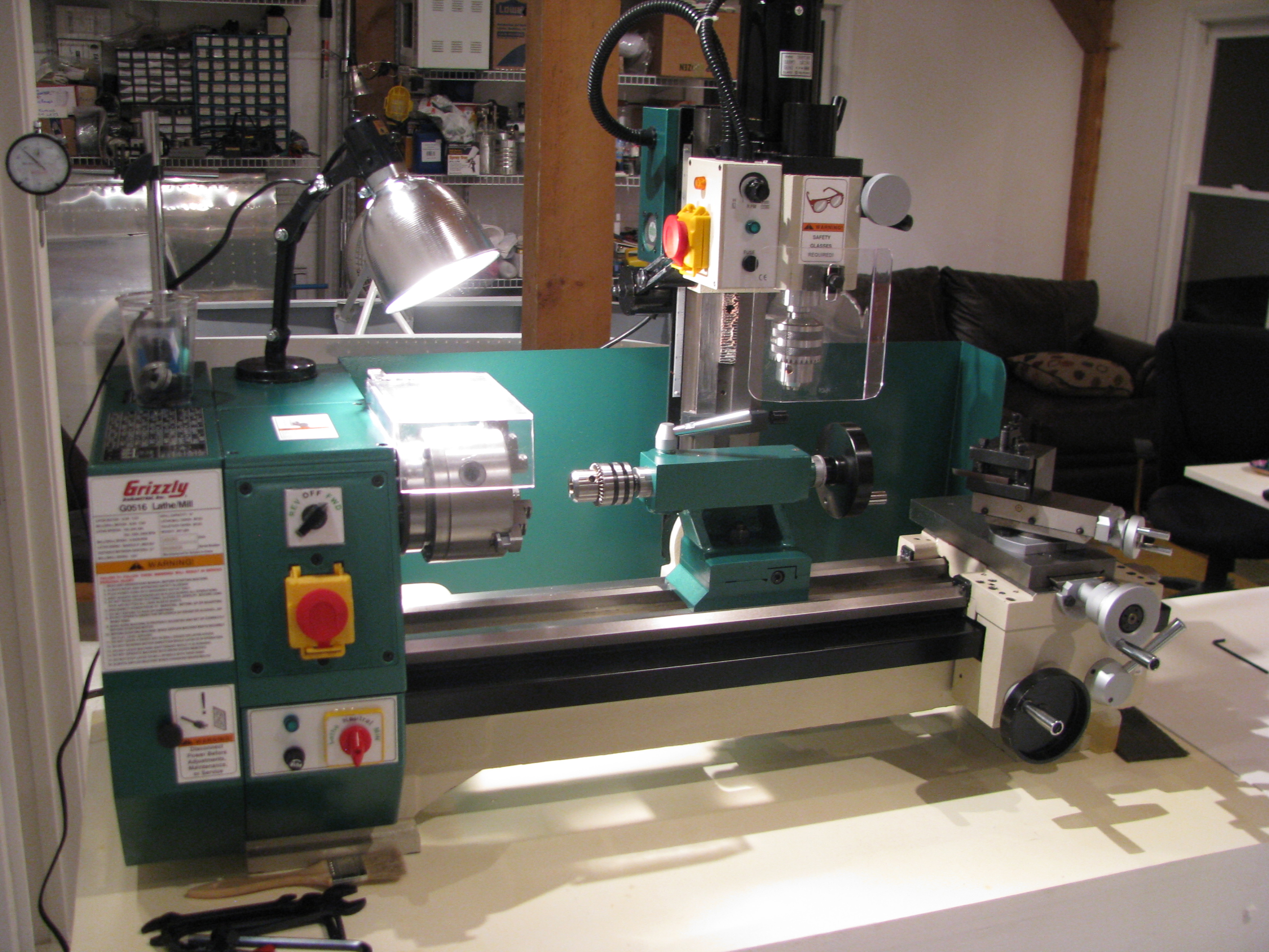
About 3 years ago I invested in a Grizzly G0516 Lathe/Mill/Drill. The lathe is great. Very capable. The drill very precise. With patience you can drill very accurate holes. Milling left a lot to be desired. It took a lot of setup and then the machining was tough with the small mill table and relatively imprecise control using the lathe slide as the table movement control.
On paper it sounds great, but like many before, I have realized its limitations and really only used it for milling maybe 4 or 5 times seriously.
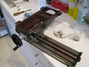
Little Machine Shop (.com) offers this milling table (shown here upside down). It is a little larger than a Sieg X2 table and the G0516 milling head bolts right to the back, effectively making a big-table X2 mill.
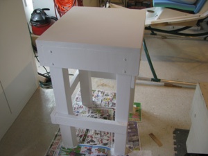
Step one is to fabricate a sturdy table made to fit in the only convenient spot left in my shop (too many projects). 4x4 legs, 2x6 table stringers, 3/4” ply and 3/4” mdf forming the top with 3 or 4 coats of urethane to seal it all up.
Everything is screwed and glued to keep it as stiff as possible. The surface is true within 0.1degree (I love my digital level).
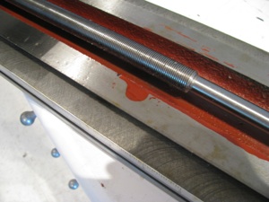
As with the lathe, the first step is to take everything apart, clean off the shipping grease, and check all the surfaces. It felt pretty bad right out of the box - very sloppy movement - alternatively too tight and too loose with lots of side play.
That shipping grease turns to something like chewing gum and some of the sliding surfaces had paint on them. Don’t even think of using these Chinese machines right out of the box.
But as with the Grizzly, after a little work the motion cleans up, smooths out, and the tolerances can be snugged up substantially.
Virtually no play on the table movement once the gibs are adjusted. The motion is kind of stiff. After some use I may lap the ways and gibs to smooth it out and allow freer motion.
Complain as folks might about the Chinese machine tools, the value per dollar is amazing.
I don’t have any pictures of my tramming - my first time doing it with any precision. It took hours. I first made a tool I could chuck up in the mill that rigidly held my dial indicator 3-4 inches off centerline.
The Y error was about 9 mils at the start. This is the fore/aft “lean” of the mill column. To adjust it you unbolt the casting that holds the giant column mount stud, tilt it the appropriate direction and add shims to the appropriate side. Very thin shims. Doing the trig showed that I needed 2.5-3.5 mils of shim. My thinnest shim stock is 5 mill brass, so I ended up using aluminum foil. Lightly grease up one side (so it sticks) and layer it together. I needed a strip about 3 layers thick to get the Y tram. Since aluminum is not the strongest, I will have to check this periodically.
Since the column is designed to tilt left and right, it is just a matter of loosening the giant bolt and tilting/bumping the head until things are accurate, then snugging it down.
I ended up with about 0.5 mil Y tram error and just less in the X. I only have a dial indicator, so this is all probably within the error of the indicator, but sufficient for anything i will need it for.
Interestingly, the Jacob’s chuck had about 1.5mills of runout (since I was measuring stuff anyway). When I switch to a milling collet I will check the runout of that to see if its the chuck or the spindle head (I hope it’s the chuck).
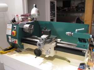
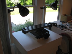
The lathe denuded of the milling head. Whenever I needed the lathe it seemed I had t set up to drill and vice versa. This new arrangement should be much more efficient and I will be more inclined to use the mill for precision drilling instead of the old drill press.
Next up is to add my DRO indicators to the mill table. I’m going to make some chips first.
Turbine Plumbing Done
05/27/13 14:29 Filed in: All
Completed plumbing of the engine oil system.

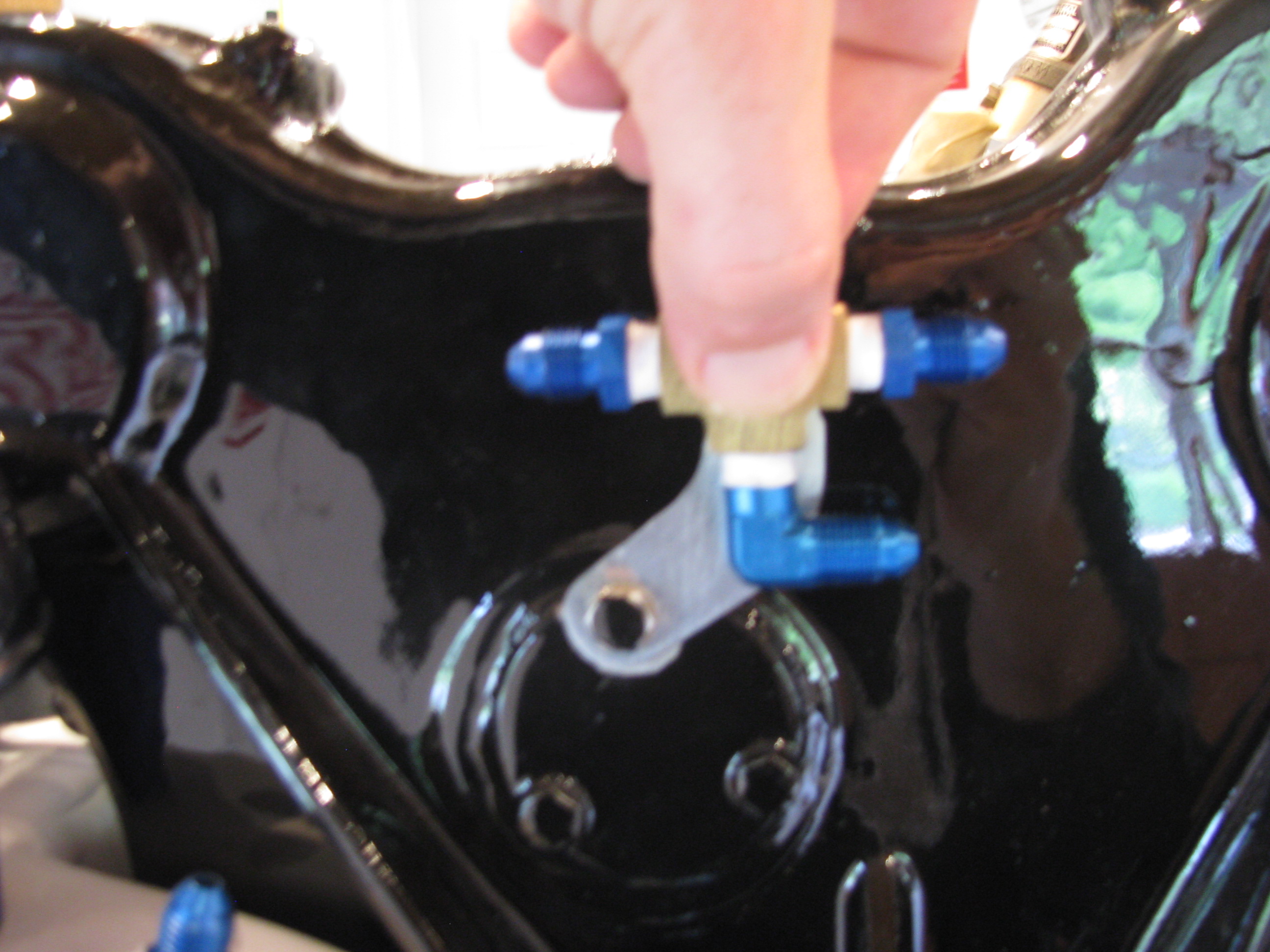
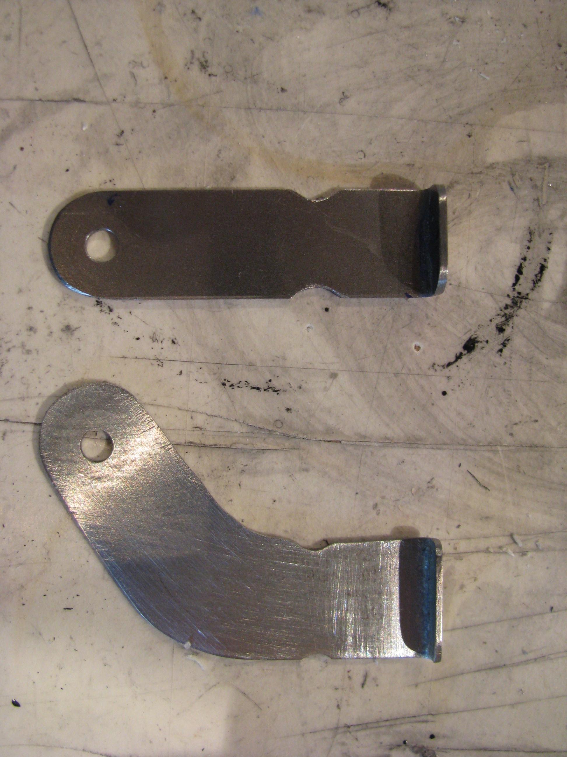
My tubing flare tool clamps just about an inch of tube, so you can’t begin a bend until then. I found it easier to offset the central Tee about an inch to be able to make the line from the top of the tank possible.
The top bracket is per BJ’s instructions. The lower one is bent for the actual offset needed so the bends were not too tight.
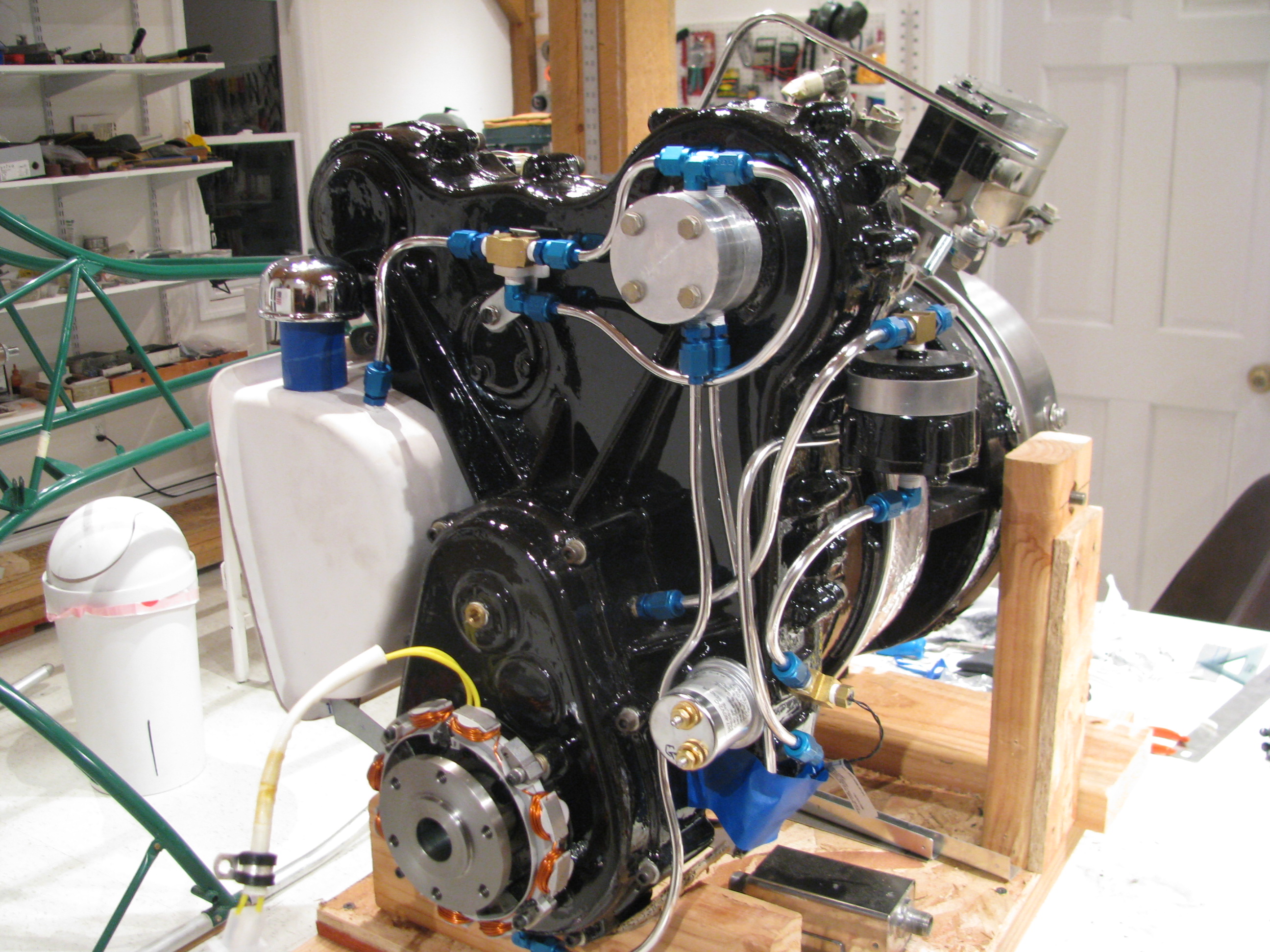
The money shot. Doing the tubing is a pleasant project. Try the run with wire first for test fitting, cut the tube, gently coax it into shape, polish, flare (don’t forget to add the fittings first - done that), and it all comes together. My son’s girlfriend said it looks like some 50’s science fiction movie prop with all the gadgets and tubes.
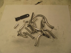
I don’t know if anyone else has the problems of a lot of scrap. This being a trial and error kind of thing I ended up with a lot of little pieces like this. I had to actually buy more Versatube from A.S.&S. to finish my job.
I got enough to make BJ’s “poor man’s oil cooler” should it be needed. I will try without first as I am in a chillier climate (especially this year). I’m not a fan of blocking the inlet airflow.
Oil Tank Fab
05/10/13 14:24 Filed in: All
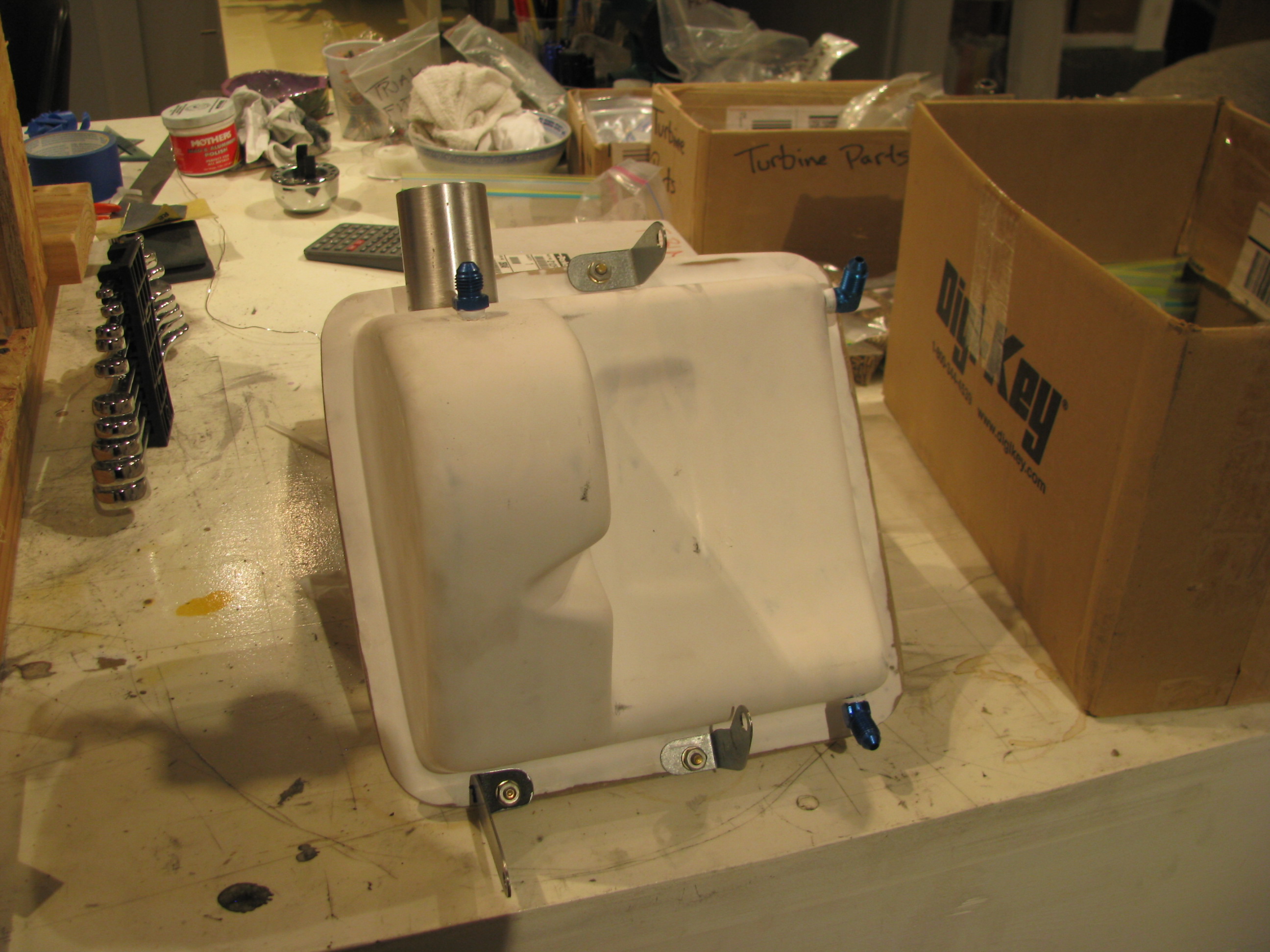
Completed Oil Tank and mounting hardware (finally).
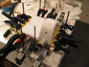
Fiberglassing together tank halves. Tidy up the insides (some stray bits of glass and cloth needed trimming, clean the surfaces with acetone, and bond the sides with a thick mixture of flox and resin.
Check for extrusion out each edge and clamp the hell out of it.
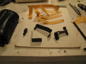
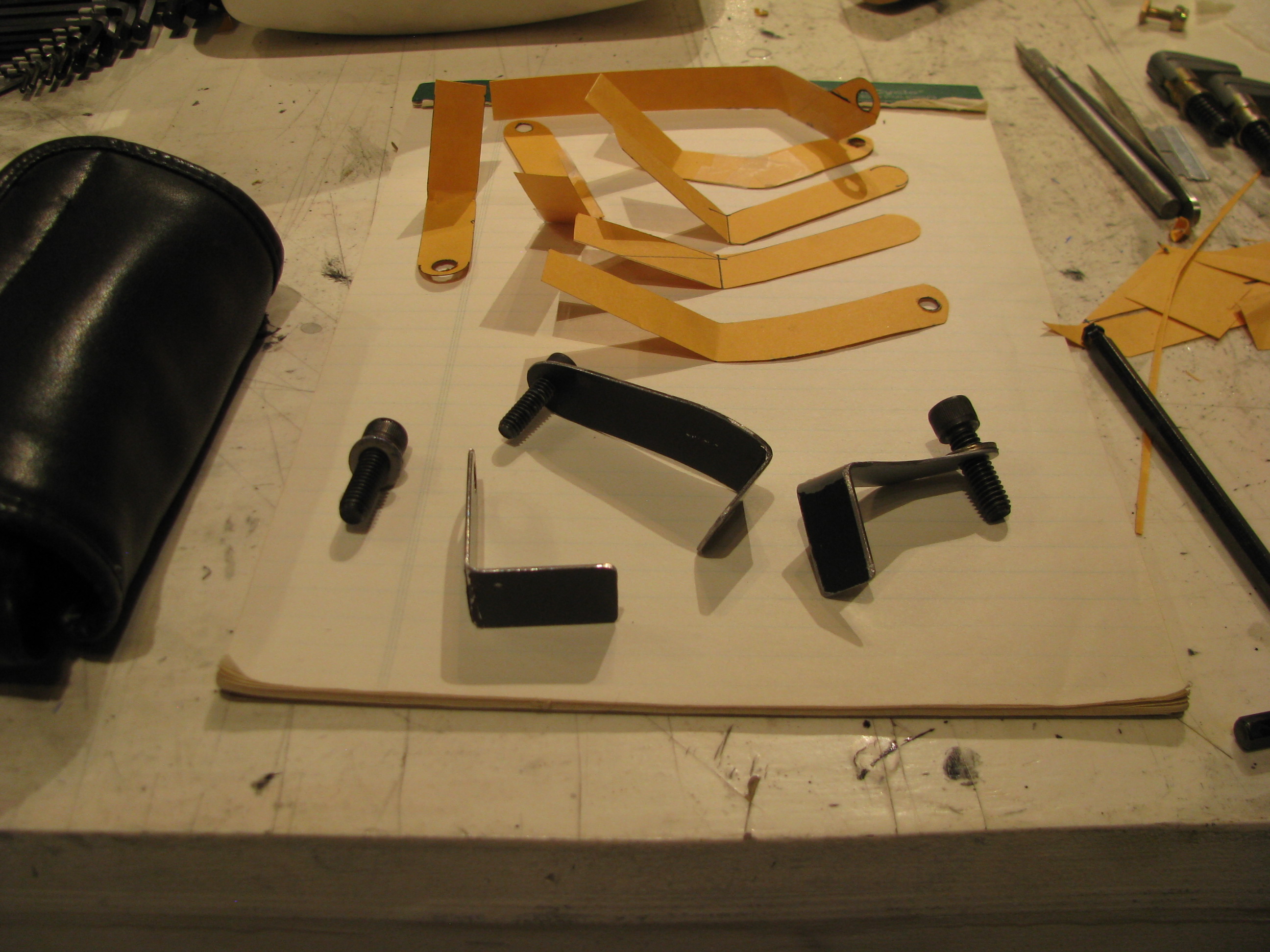
The tank mount brackets. You can see my many trial cardboard templates.
Thankfully I had an old ZVBox case that was 0.048” steel which I could use as a donor since there really isn’t enough steel strapping supplied to make the brackets, especially in the weird shapes you actually need, as opposed to the nice straight ones that BJ shows.
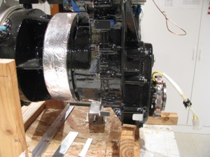
The videos show only two mounting points, top and bottom. I added a third using the one of the lower forward case bolts as the mount point. This takes it from something that could vibrate with some play to being very, very rigid to the engine.
There are a few points in the instructions like this, where it seems a very simple mod can add immensely to the strength/quality. I am sure I’m not the first to do this.

Finished tank with fittings mounted. I glassed the tank in the fall, but only just now finished mounting it this spring. My long winter of distractions, international travel, and business has ended and I plan on making very good progress on the helicopter again.

Fiberglassing together tank halves. Tidy up the insides (some stray bits of glass and cloth needed trimming, clean the surfaces with acetone, and bond the sides with a thick mixture of flox and resin.
Check for extrusion out each edge and clamp the hell out of it.
The tank mount brackets. You can see my many trial cardboard templates.
Thankfully I had an old ZVBox case that was 0.048” steel which I could use as a donor since there really isn’t enough steel strapping supplied to make the brackets, especially in the weird shapes you actually need, as opposed to the nice straight ones that BJ shows.

The videos show only two mounting points, top and bottom. I added a third using the one of the lower forward case bolts as the mount point. This takes it from something that could vibrate with some play to being very, very rigid to the engine.
There are a few points in the instructions like this, where it seems a very simple mod can add immensely to the strength/quality. I am sure I’m not the first to do this.
Finished tank with fittings mounted. I glassed the tank in the fall, but only just now finished mounting it this spring. My long winter of distractions, international travel, and business has ended and I plan on making very good progress on the helicopter again.
Panel Cut & Delivered
04/01/13 17:23 Filed in: All
Panel Received. I discovered an online service called eMachineShop.com
This service will take a simple drawing and machine up a part for you. My method is to model the item in a “real” CAD system (in my case SpaceClaim), then import the drawing into their proprietary tool. You could do all your modeling in their tool, but it’s pretty primitive and yet another tool to learn. Select the material, and once it passes their design rule checks submit the part. A week later you get the item delivered. My panel cost me about $95 in 6061-T6 0.090” aluminum. I wanted some beef on the panel thickness to avoid having to add support structure for the planned avionics.

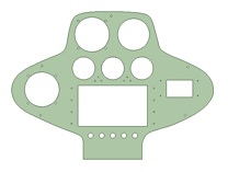
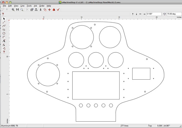
I took my aluminum “test fit” piece, traced it on graph paper, measured the points, and splined up the outline. Then I rough-modeled the instruments, shuffled them around and “cut” the holes. Everything is tight or slightly undersized so I can trim for a nice snug fit. As BJ says, it’s easier to remove metal than to add it back in.
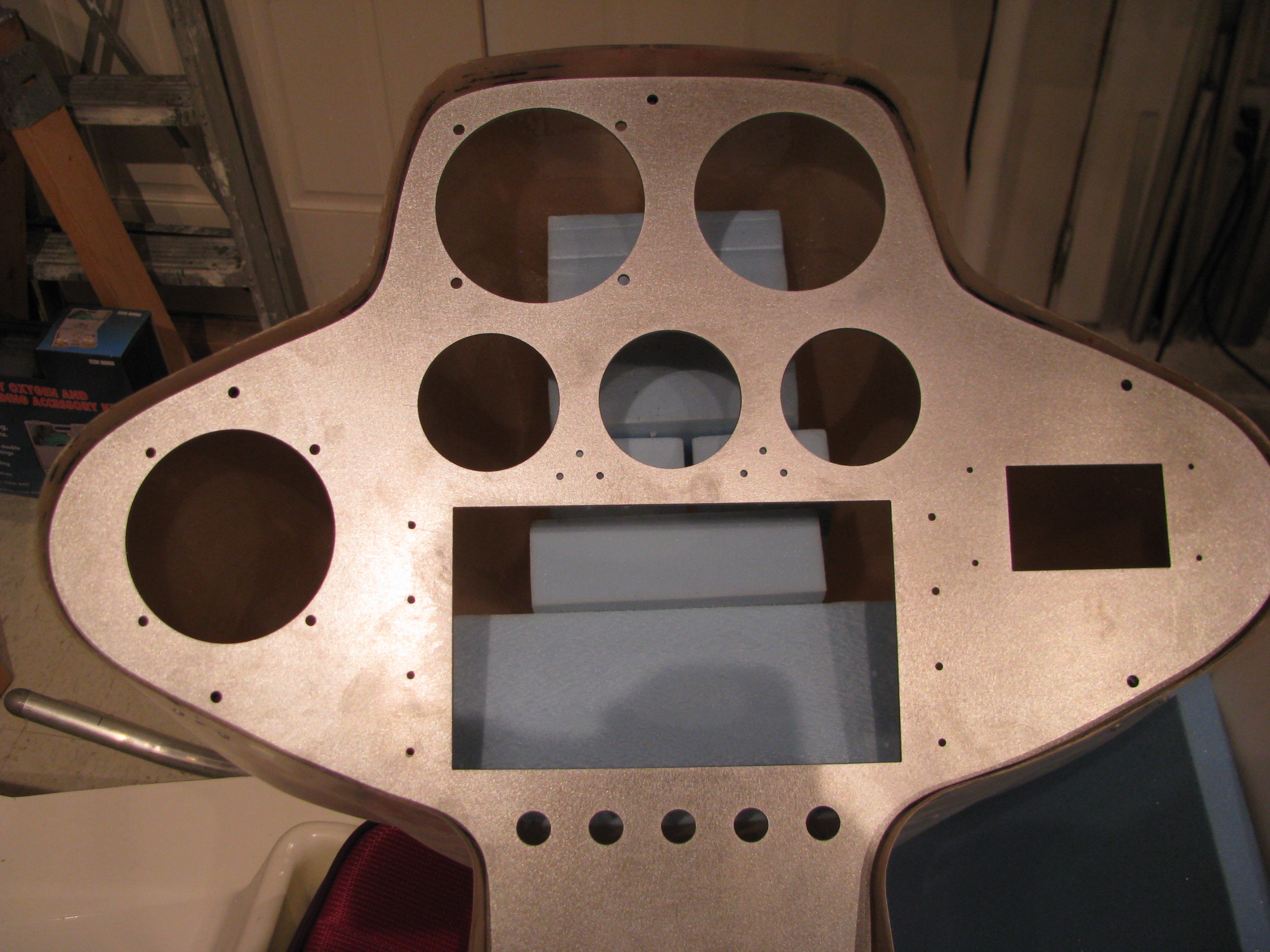
And here is the finished item. It was returned in just over a week and fits perfectly. Some of the holes need trimming, but that was expected as I wanted a nice snug fit.
Here are the links to the rough DXF’s of my panel that I used to import into eMachineshop’s tools:
PanelMock1.A.dxf
LowerPanel.dxf

Compass Bug Killed!
03/28/13 17:22 Filed in: All
FINALLY!!! I had one last bug to track down that was annoying the hell out of me. Very occasionally I would turn the digital compass on and it would be 20degrees off and stay that way until I had power cycled the unit a bunch of times. I scrubbed the code for uninitialized variables. Filtered the heck out of the power. No change.
Experimentally I found that my lab supply was the problem. The HMC5883L must go through some internal initialization at power up. I have a big honking lab DC power supply. Whenever I turn it off and on I get a relay click and a big hum - must be charging some caps or something. Anyway, when that occurs the compass chip must latch onto some stray field being put out by the supply which screws up its internal power-up calibration routine. Certain relationships and distances between the compass and the supply proved to be worse than others.
Using a different supply, or just a separate switch from the lab supply’s switch got rid of this behavior. Nice to have it understood/killed. My experience is that if you have a bug on the bench, even a very rare one, it will occur in the field - probably at the worst possible moment.
Electronic Compass
02/10/13 17:11 Filed in: All
Detour into Electronics Land. For several months I have been tied up doing other projects keeping me away from the helicycle and then started looking into the panel instruments.
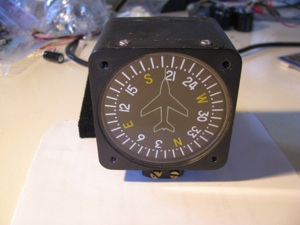
Every aircraft seems to have one of these, so I just assumed I should get one as well, so bought one from Wentworth on eBay for about $200.
It’s awful. Sticky motion and inaccurate (+/- 5 to 10 degrees). Now this one is used, and does not work as well as the one in my plane, but - damn - there has to be a better way to tell direction than sticking one off these butt -ugly devices on the top of the instrument pod.
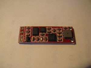
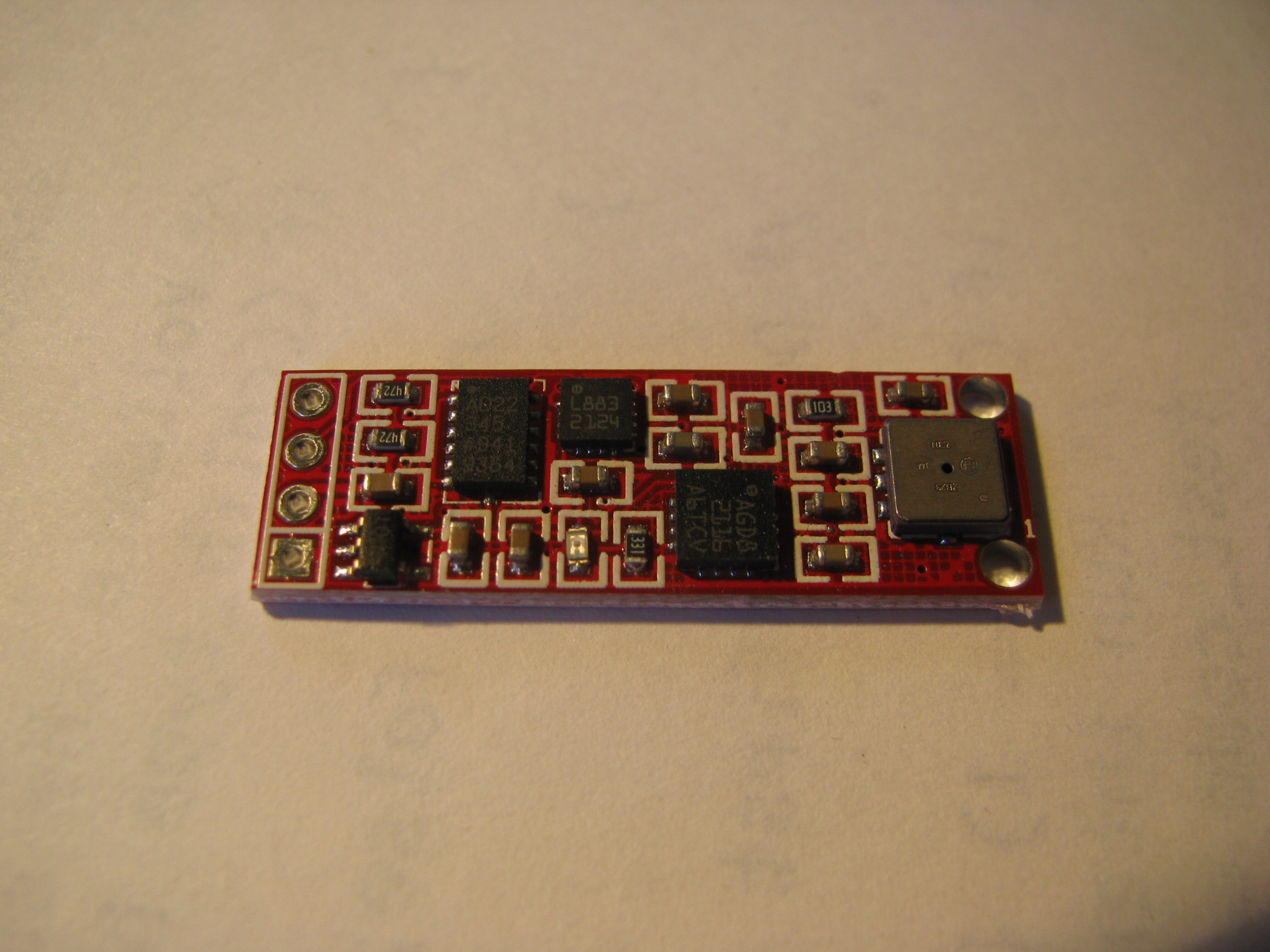
Looking around the web revealed these little gems. This is basically an inertial navigation system on a little 1.5cm x4cm card.
Onboard there is a compass chip, a 3-axis accelerometer, a 3-axis rate gyro, and a barometer that tells temperature as well. All this for <$20.
Seems like one should be able to build a compass out of this pretty easily.
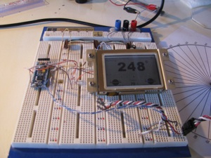
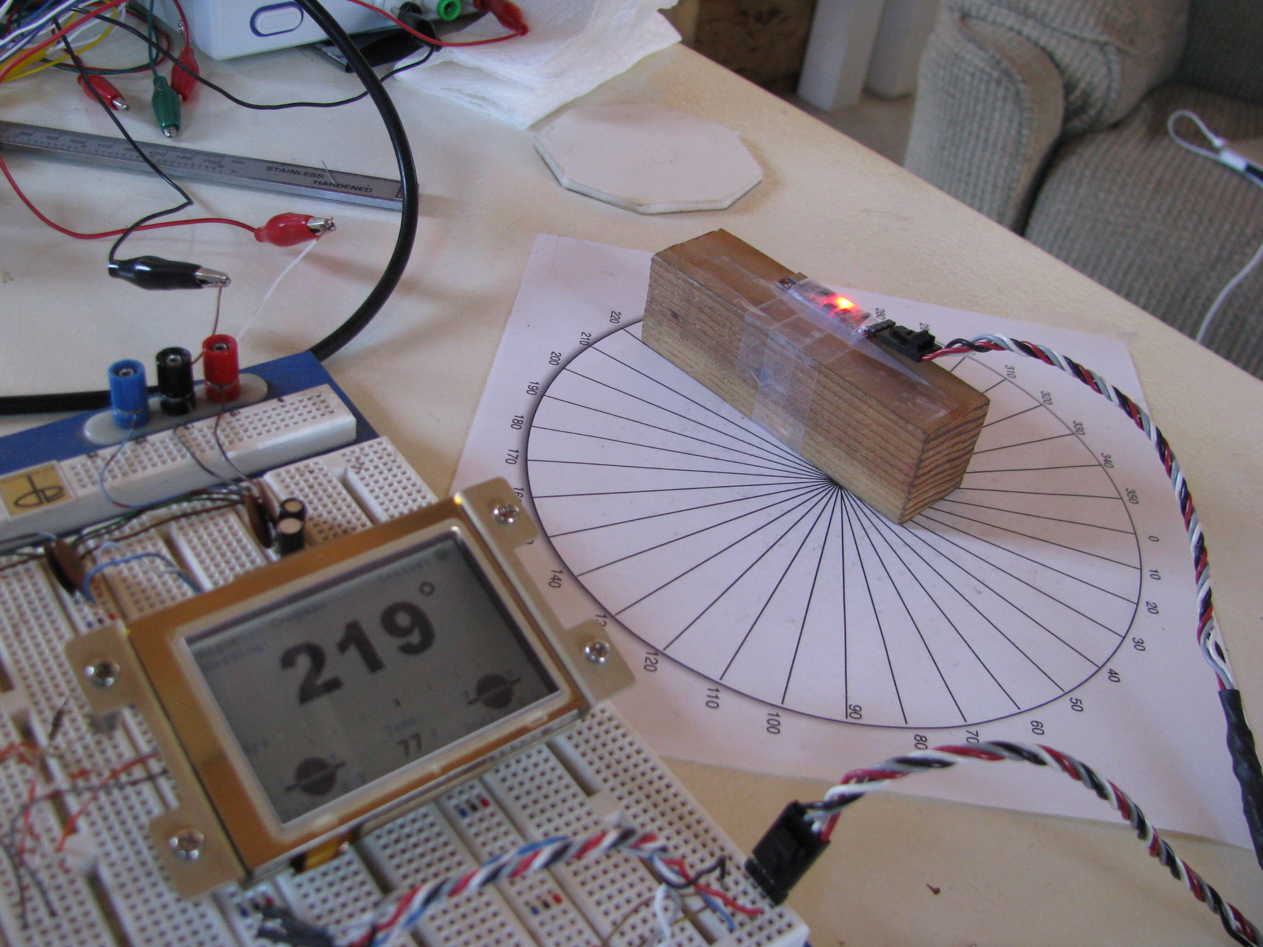
I took the opportunity to learn about the Arduino. Neat little micro - fairly self-contained with a well-developed open-source IDE. That‘s a sunlight readable LCD from EARTHLCD.
The display is driven by a serial line from the Arduino and the IMU module is interfaced via I2C. All-in-all some very simple wiring to get the whole mess working. Of course this will all get packaged up cleanly before installation for real.
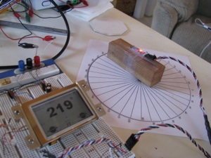
The test jig. The rose is calibrated with a fluid compass to point North. The IMU is just taped to a block of wood. It’ll be mounted up in the nose of the instrument cluster pod.
I learned a lot about the earth’s magnetic field and compasses. I did not realize that the primary magnetic force vector points 70 degrees downward at my position on the planet.
What that means is that the compass works well if level, but is WAY off if tilted by even a degree or two. The solution is to use Z-axis of the magnetic field reading and the accelerometer to detect tilt. Then do the 3-D vector trigonometry to correct and compensate for the tilt.
All of this is a lot of math and was a good challenge. It’s been years since I did matrix operations and lots and lots of trig.
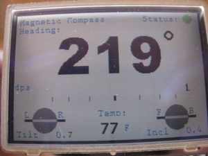
In the center there is a turn rate bar that varies in proportion to the rate of angular turn. Just like in a commercial gyro, the 3dps reading is a half scale bar. The bar deflection is proportional to the rate of turn and the displacement scale is exponential. The tilt readings are displayed since I had to compute them for the compass anyway. I calibrated the tilt against my $200 digital level and it is just as accurate.
For the uber-weenies out there, the code is attached. I make no license or warrantee that this will work for you. It works for me and that’s all I care about right now.
Air_Instrument5.ino Main program with primary execution loop
ADXL_Support.ino Support routines needed for accelerometer device
AI_Support.ino General purpose routines and conversions
AI_Types.h Data type definitions for passing vectors around
BMP085_Support.ino Routines for handling the barometric and temp sensor
Compass_Support.ino Routines for initializing, calibrating & reading the Compass Device
EZLCD_Support.ino Display device routines and drawing methods
Gyro_Support.ino Routines for driving the rate gyro device
I am extra-happy with the tilt compensation. You can now tilt the device (and ultimately the helicopter) up to about 70 degrees off level in any direction and the magnetic heading is still accurate. There is NO mechanical compass I know of that has that sort of performance envelope. Along the way I learned a ton. I plan to use that knowledge to build an airspeed indicator accurate to 5mph or less.

Every aircraft seems to have one of these, so I just assumed I should get one as well, so bought one from Wentworth on eBay for about $200.
It’s awful. Sticky motion and inaccurate (+/- 5 to 10 degrees). Now this one is used, and does not work as well as the one in my plane, but - damn - there has to be a better way to tell direction than sticking one off these butt -ugly devices on the top of the instrument pod.
Looking around the web revealed these little gems. This is basically an inertial navigation system on a little 1.5cm x4cm card.
Onboard there is a compass chip, a 3-axis accelerometer, a 3-axis rate gyro, and a barometer that tells temperature as well. All this for <$20.
Seems like one should be able to build a compass out of this pretty easily.

I took the opportunity to learn about the Arduino. Neat little micro - fairly self-contained with a well-developed open-source IDE. That‘s a sunlight readable LCD from EARTHLCD.
The display is driven by a serial line from the Arduino and the IMU module is interfaced via I2C. All-in-all some very simple wiring to get the whole mess working. Of course this will all get packaged up cleanly before installation for real.
The test jig. The rose is calibrated with a fluid compass to point North. The IMU is just taped to a block of wood. It’ll be mounted up in the nose of the instrument cluster pod.
I learned a lot about the earth’s magnetic field and compasses. I did not realize that the primary magnetic force vector points 70 degrees downward at my position on the planet.

What that means is that the compass works well if level, but is WAY off if tilted by even a degree or two. The solution is to use Z-axis of the magnetic field reading and the accelerometer to detect tilt. Then do the 3-D vector trigonometry to correct and compensate for the tilt.
All of this is a lot of math and was a good challenge. It’s been years since I did matrix operations and lots and lots of trig.
In the center there is a turn rate bar that varies in proportion to the rate of angular turn. Just like in a commercial gyro, the 3dps reading is a half scale bar. The bar deflection is proportional to the rate of turn and the displacement scale is exponential. The tilt readings are displayed since I had to compute them for the compass anyway. I calibrated the tilt against my $200 digital level and it is just as accurate.
For the uber-weenies out there, the code is attached. I make no license or warrantee that this will work for you. It works for me and that’s all I care about right now.
Air_Instrument5.ino Main program with primary execution loop
ADXL_Support.ino Support routines needed for accelerometer device
AI_Support.ino General purpose routines and conversions
AI_Types.h Data type definitions for passing vectors around
BMP085_Support.ino Routines for handling the barometric and temp sensor
Compass_Support.ino Routines for initializing, calibrating & reading the Compass Device
EZLCD_Support.ino Display device routines and drawing methods
Gyro_Support.ino Routines for driving the rate gyro device
I am extra-happy with the tilt compensation. You can now tilt the device (and ultimately the helicopter) up to about 70 degrees off level in any direction and the magnetic heading is still accurate. There is NO mechanical compass I know of that has that sort of performance envelope. Along the way I learned a ton. I plan to use that knowledge to build an airspeed indicator accurate to 5mph or less.
Beacon Strobe
02/10/13 13:34 Filed in: All
Working my way forward, I knew I wanted a strobe of some form. Traditional commercial strobes are expensive, heavy, and generate several hundred volt spikes that have to be well contained or will play hell with your electronics and radio.
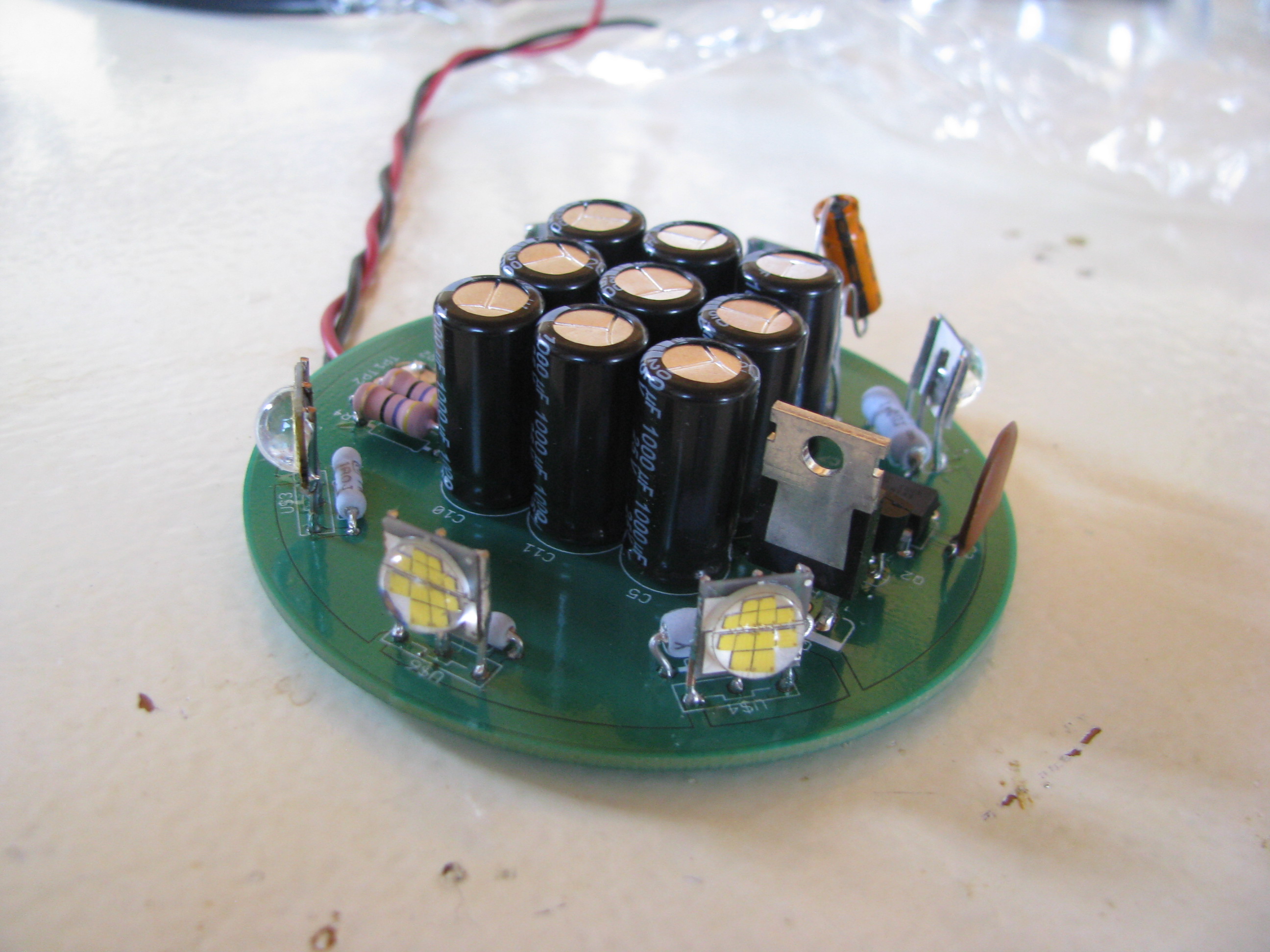
LED technology has made leaps and bounds in recents years. I decided to build my own strobes based on some new 900 Lumen CRE LEDs. That’s 900 lumens each. My old-fashioned living-room flood light bulbs are each 800 lumens at 90watts, just to put that in perspective. According to the spec sheet you can get almost twice that light per device if it is not continuous duty by overdriving the current.
So six of these LEDs with a peak of 1800 lumens each gets us about 10,000 lumens. The trick is handling the current. At 4amps per device that’s 24 amps. You certainly don’t want to switch that on and off directly from the battery. The current loop in the ship’s wiring would induce its own set of problems.
So to deal with that I developed a little circuit that charges up a capacitor bank, discharges through the LEDs then charges up again. The sequence is a 25millisecond flash, pause 100 milliseconds, another 25 millisecond flash, then pause 1.5 seconds, repeat forever. The caps charge during that 1.5second delay and therefore the average current to the whole strobe unit is 0.3A at 12V and should be very easy on the rest of the ship’s systems.
Best of all, the thing weighs next to nothing. I haven’t measured, but it can’t be more than a couple of ounces.
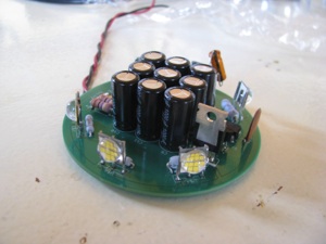
Here’s the circuit. Ignore the two capacitors dangling in the breeze. They are bulk and decoupling for the ATTiny85 microcontroller that controls the sequence. I forgot to order SMT caps from Digikey and will replace those before buttoning it up.
For those interested the schematic can be seen at Strobe_A.pdf. If you do something like this, pay attention to the ripple current rating of the capacitors. Layout is Strobe_A_top.pdf.

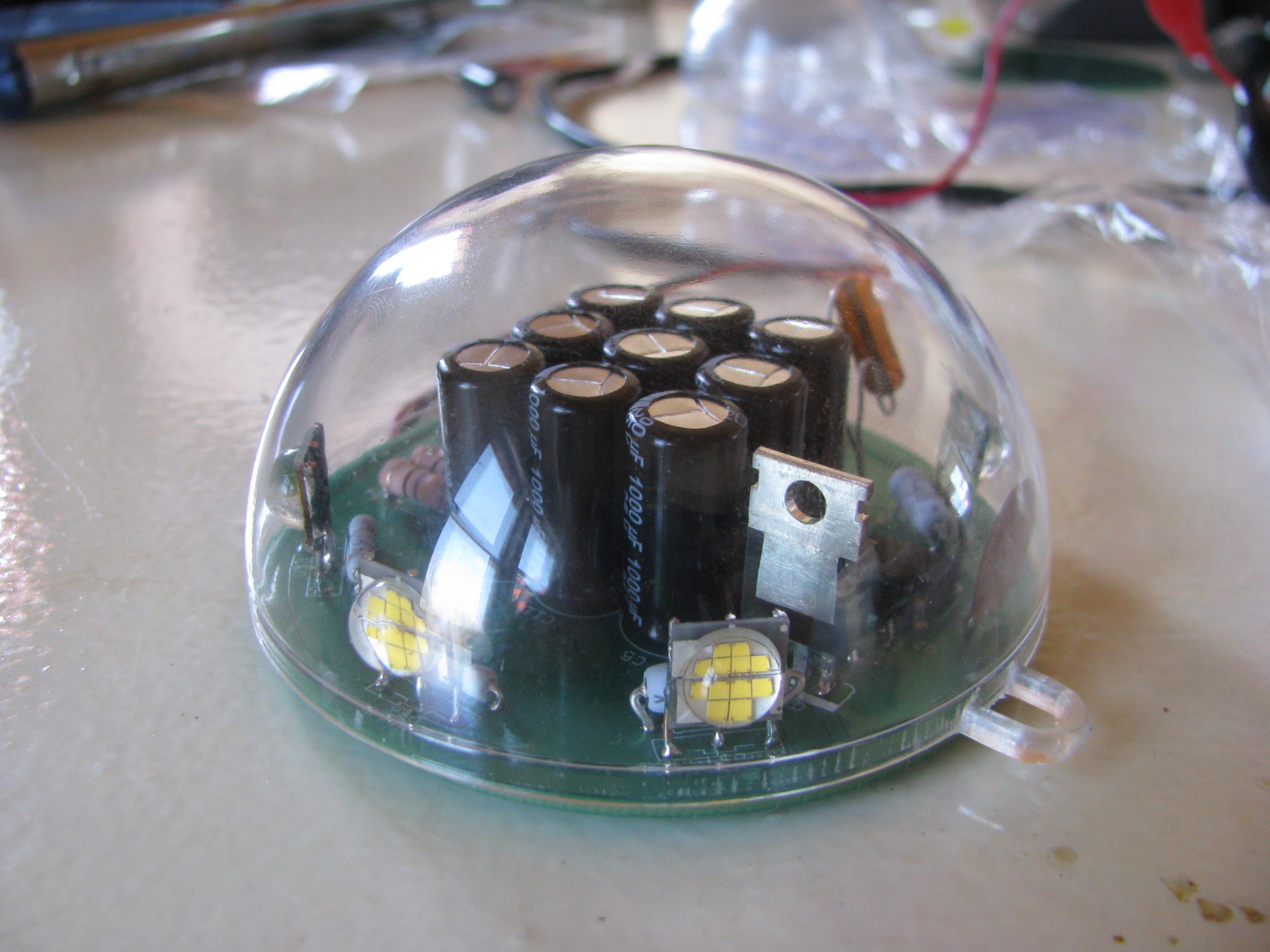
The PCB was sized to fit in a polycarbonate sphere bought at a craft store. The shell is designed to be used as a homemade christmas ornament.
I used Sunstone circuits “Value Proto” service for my PCB. This is a very cheap PCB fab process that uses unused panel space on other designs going through to keep your individual cost down. The down side is that the lead time can be long since they have to wait for a design with spare panel space - but hey, it’s very, very cheap.
If you do something like this, bear in mind that if the lights were left ON continuously (not blinking) it would heat up quickly and destroy itself. This circuit only works if the duty cycle (lights on period) is very, very low. I have left it running for days blinking along with no problems and cool to the touch, with flash pulses that are retina-melting. If you look at it directly by mistake you will see spots for an hour.
LED technology has made leaps and bounds in recents years. I decided to build my own strobes based on some new 900 Lumen CRE LEDs. That’s 900 lumens each. My old-fashioned living-room flood light bulbs are each 800 lumens at 90watts, just to put that in perspective. According to the spec sheet you can get almost twice that light per device if it is not continuous duty by overdriving the current.
So six of these LEDs with a peak of 1800 lumens each gets us about 10,000 lumens. The trick is handling the current. At 4amps per device that’s 24 amps. You certainly don’t want to switch that on and off directly from the battery. The current loop in the ship’s wiring would induce its own set of problems.
So to deal with that I developed a little circuit that charges up a capacitor bank, discharges through the LEDs then charges up again. The sequence is a 25millisecond flash, pause 100 milliseconds, another 25 millisecond flash, then pause 1.5 seconds, repeat forever. The caps charge during that 1.5second delay and therefore the average current to the whole strobe unit is 0.3A at 12V and should be very easy on the rest of the ship’s systems.
Best of all, the thing weighs next to nothing. I haven’t measured, but it can’t be more than a couple of ounces.
Here’s the circuit. Ignore the two capacitors dangling in the breeze. They are bulk and decoupling for the ATTiny85 microcontroller that controls the sequence. I forgot to order SMT caps from Digikey and will replace those before buttoning it up.
For those interested the schematic can be seen at Strobe_A.pdf. If you do something like this, pay attention to the ripple current rating of the capacitors. Layout is Strobe_A_top.pdf.
The PCB was sized to fit in a polycarbonate sphere bought at a craft store. The shell is designed to be used as a homemade christmas ornament.
I used Sunstone circuits “Value Proto” service for my PCB. This is a very cheap PCB fab process that uses unused panel space on other designs going through to keep your individual cost down. The down side is that the lead time can be long since they have to wait for a design with spare panel space - but hey, it’s very, very cheap.
If you do something like this, bear in mind that if the lights were left ON continuously (not blinking) it would heat up quickly and destroy itself. This circuit only works if the duty cycle (lights on period) is very, very low. I have left it running for days blinking along with no problems and cool to the touch, with flash pulses that are retina-melting. If you look at it directly by mistake you will see spots for an hour.