
Mill Power Feed
07/08/13 18:39 Filed in: All
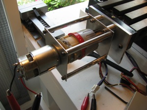
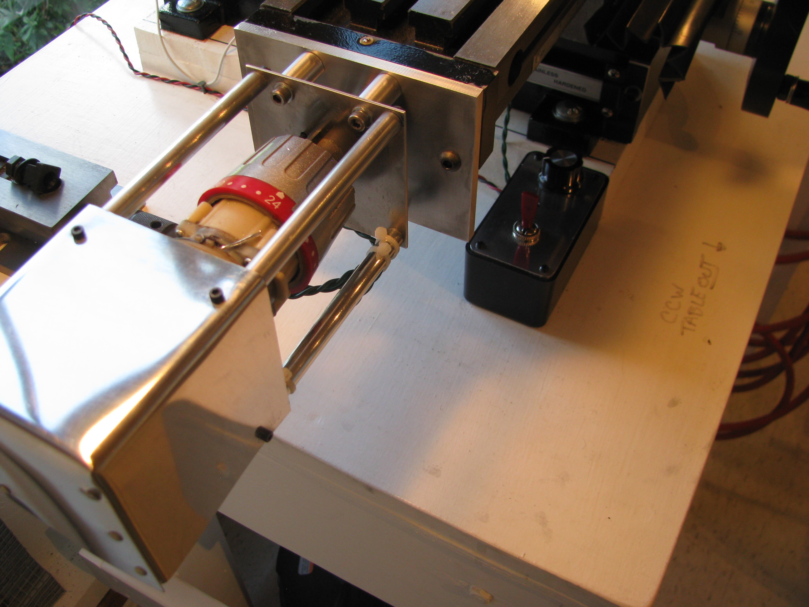
Power Feed. After milling for a bit it is pretty evident that a power feed is definitely a time and wrist saver. I had a cordless Harbor Freight Hammer Drill that I never liked all that much that served as a donor for the motor and gearbox. I stripped it down discarded the electronics and lathed off the notched ring that gave it the hammer action.
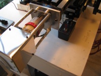
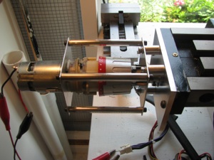 I used it as an exercise in machining to build a frame to hold the gearbox and make an adapter plate to fit the mill.
For airplane parts it is common practice to drill parts in assembly. In this case however, I made sketches and machined all the parts to spec, being careful on all the measurements. Even though not necessary, I was able to hold tolerances to +/- 0.001” on all dimensions. Not bad for a noob. Everything fit together with very tight tolerance and no play anywhere. Satisfying.

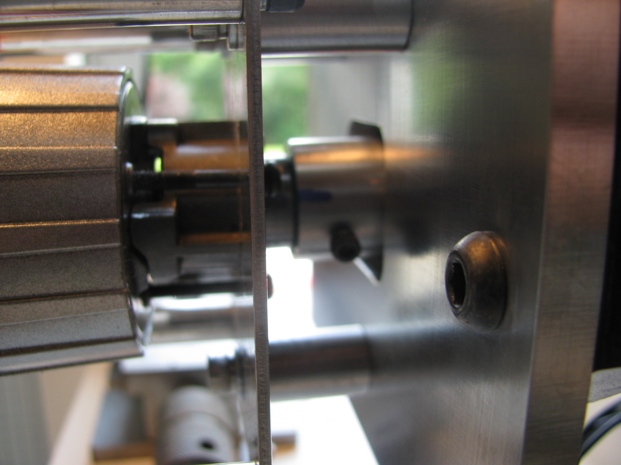
To link the drill shaft to the X-axis lead screw, I machined a coupler with a tongue that mates to a slot already present in the lead screw, and then drilled a hole through the coupler and drill shaft.
The coupler is threaded for a couple of 4-40 allen screws. When they are backed out the coupler spins freely on the drill shaft in case I want to machine without the power feed engaged. A little cumbersome and it it becomes a pain I will fit a quick-release pin instead of the screws.

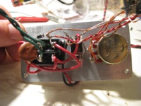
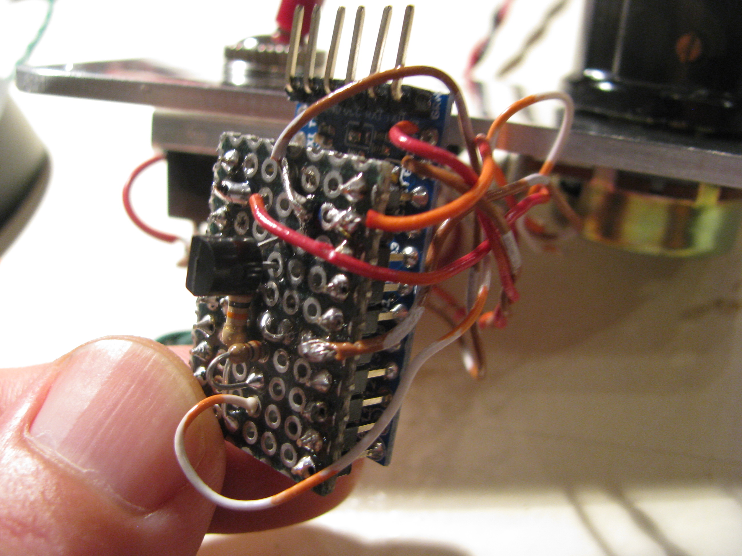
Speed Control for Power Feed. Being hooked up on the Arduino, I whipped up a little PWM program. It reads the voltage on a linear pot and adjusts a PWM signal output width. I just used a DPDT-Center Off switch to change direction and turn it off, so the Arduino’s job is simple. Just read a POT, adjust the PWM pulse width and drive a power FET (IRFZ44). A little Radio Shack Project box with the aluminum cover replaced with a 0.125” plate machined to accept the switch, POT, doubles as the heat sink for the FET as well. Works great.


For airplane parts it is common practice to drill parts in assembly. In this case however, I made sketches and machined all the parts to spec, being careful on all the measurements. Even though not necessary, I was able to hold tolerances to +/- 0.001” on all dimensions. Not bad for a noob. Everything fit together with very tight tolerance and no play anywhere. Satisfying.
To link the drill shaft to the X-axis lead screw, I machined a coupler with a tongue that mates to a slot already present in the lead screw, and then drilled a hole through the coupler and drill shaft.
The coupler is threaded for a couple of 4-40 allen screws. When they are backed out the coupler spins freely on the drill shaft in case I want to machine without the power feed engaged. A little cumbersome and it it becomes a pain I will fit a quick-release pin instead of the screws.

Speed Control for Power Feed. Being hooked up on the Arduino, I whipped up a little PWM program. It reads the voltage on a linear pot and adjusts a PWM signal output width. I just used a DPDT-Center Off switch to change direction and turn it off, so the Arduino’s job is simple. Just read a POT, adjust the PWM pulse width and drive a power FET (IRFZ44). A little Radio Shack Project box with the aluminum cover replaced with a 0.125” plate machined to accept the switch, POT, doubles as the heat sink for the FET as well. Works great.