
2011
TR Gearbox Prep
12/30/11 23:39 Filed in: All
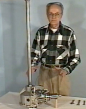
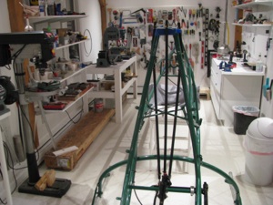
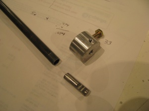
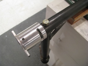
OK. Time for the serious stuff; Mounting the main transmission, tail rotor shaft and tail rotor gearbox. Once the main transmission is mounted, the tail rotor shaft can be fabricated and aligned. That’ll go a really long way to making the whole thing start to look like a helicopter. To date the bits go on, then they come off, so anytime my kids stop by the shop it looks like I am back a square one.
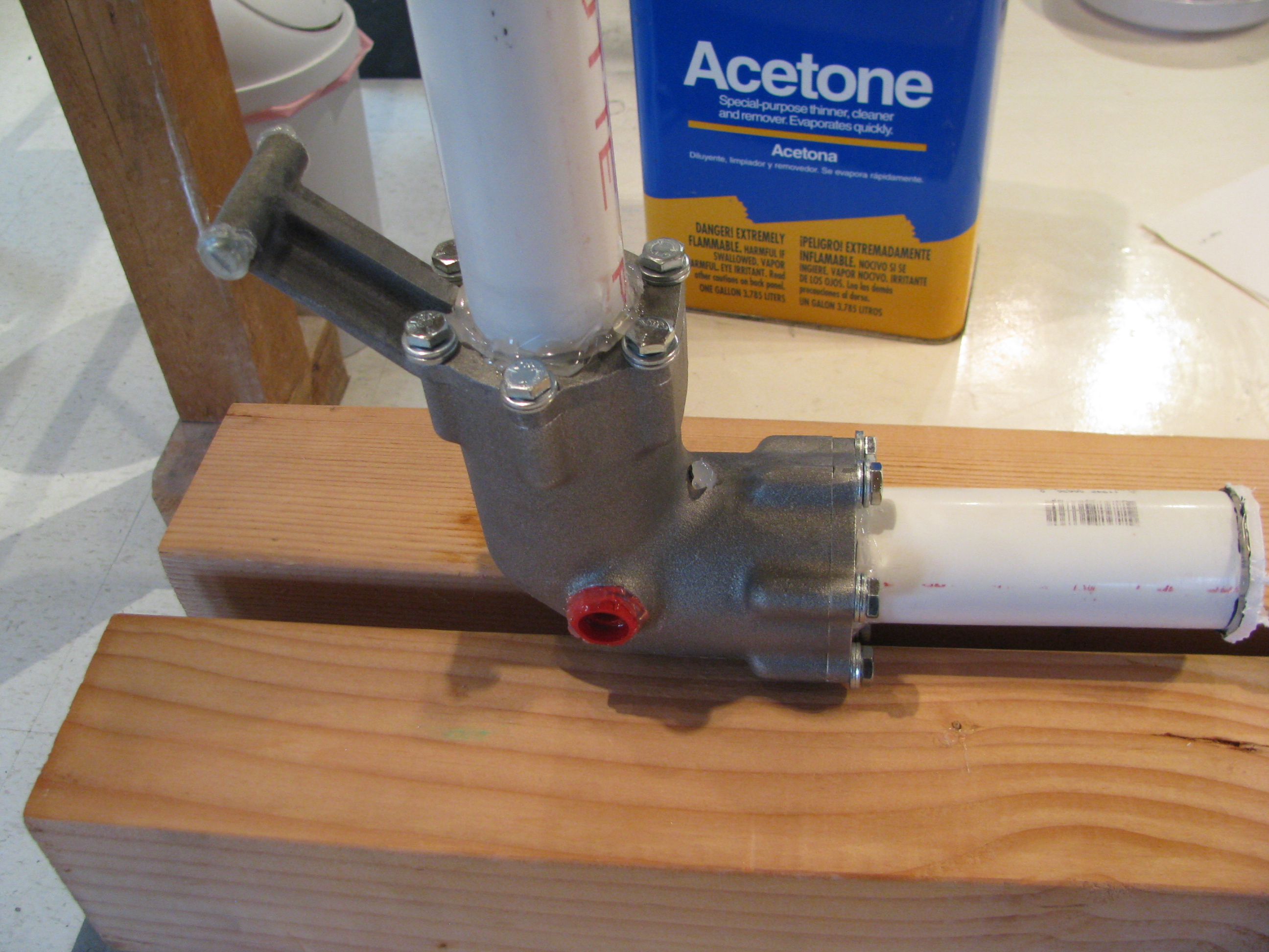
Baby Steps: I masked off the important bits of the rail rotor gearbox. That’s just PVC with hot glue around the bearings. The the exterior got a sandblast with 220 grit glass, blown off, and rinsed with acetone.
Those are cheap HW store 1/4-28 bolts since they’ll get blasted too.
I ordered a gallon of the Allisyn ProGear21 75W-90W oil today. Holy crap! $60/gallon.

Wow. POR-15! Magic stuff. Two coats and this thing looks great. It’s like coating it with a form-fitting layer of glass. From reading the web I have to resist the strong temptation to touch it since it can take days to completely dry.
I wanted to try something small before committing to the main transmission with the POR-15. I have no reservations at this point. Some folks use color on these parts, but I like the effect of keeping the mechanical parts looking like manly hardware.
Important note on the POR-15: Don’t mix it in a plastic cup! The first little bit sat for a minute, then ate through the cup (polycarbonate, I think) and then ate through the coat of polyurethane on my workbench. Strong stuff. I had to steal a glass form the kitchen, then dig around for a camel hair brush instead of the little plastic one I was going to originally use.
I also ordered a transmission lift strut from Hap Miller today (nice guy!). I’ve heard good things about it from Juan R’s site and really don’t like the “heat and smash” tubes that are used in a number of places. I’ll probably use his tail fin braces as well.
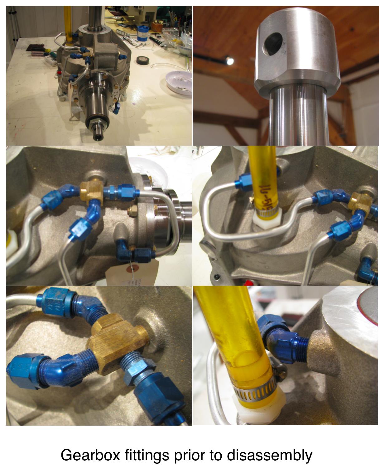
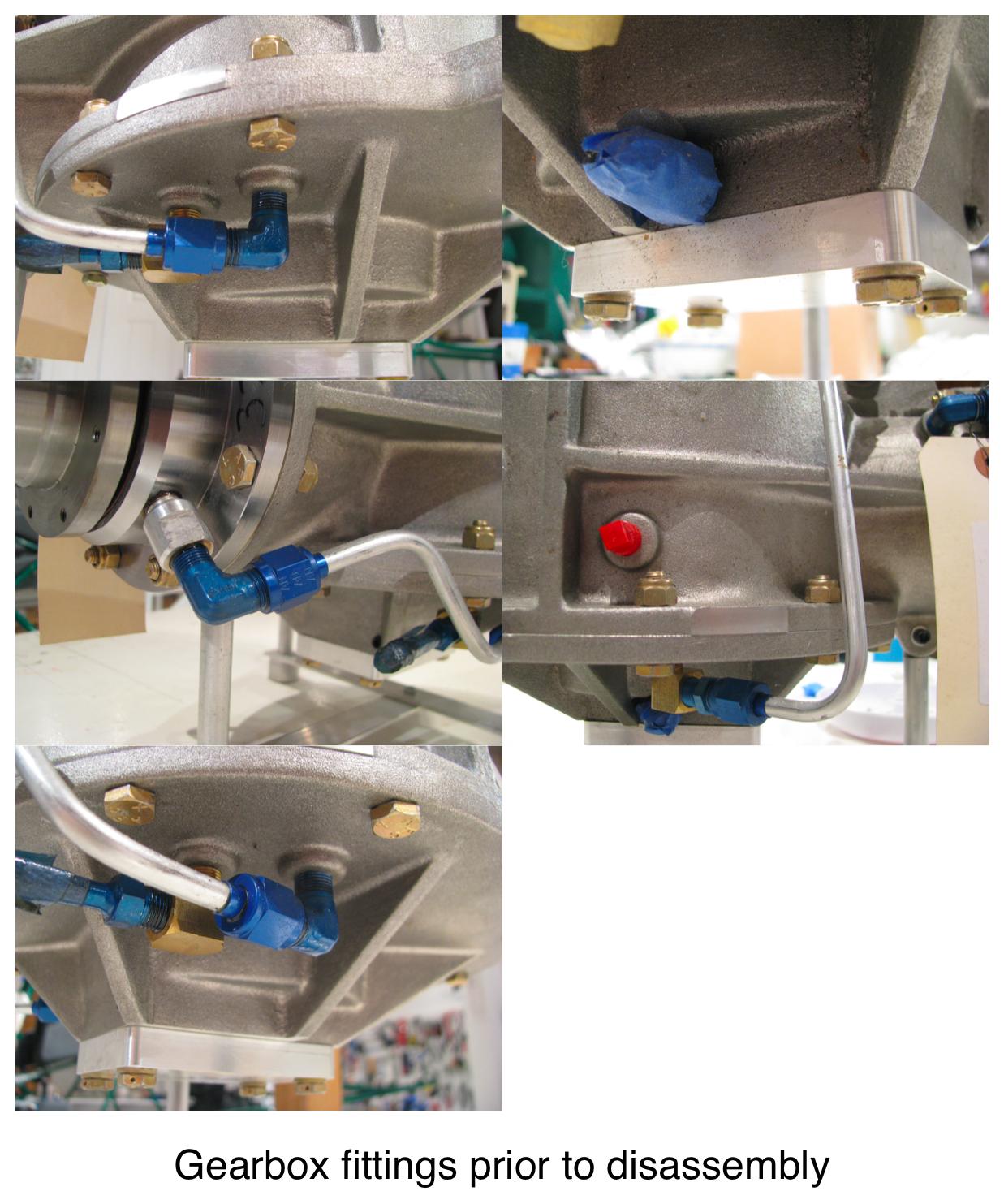
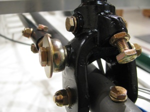
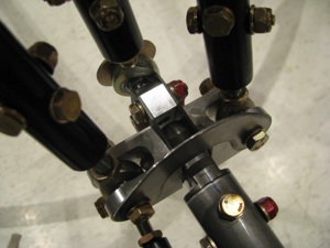
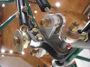
Prior to painting the main transmission I took a series of photos so I would have a reference for where the various tubes and fittings go on reassembly.
GearboxPlumbing_1.jpg
GearboxPlumbing_2.jpg
GearboxPlumbing_3.jpg
Aux Tank Mounting
12/01/11 23:32 Filed in: All

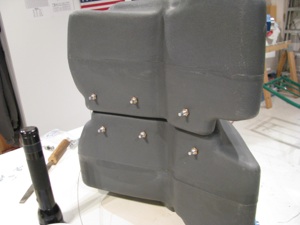
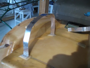
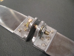
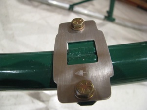
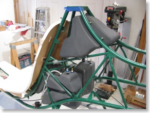
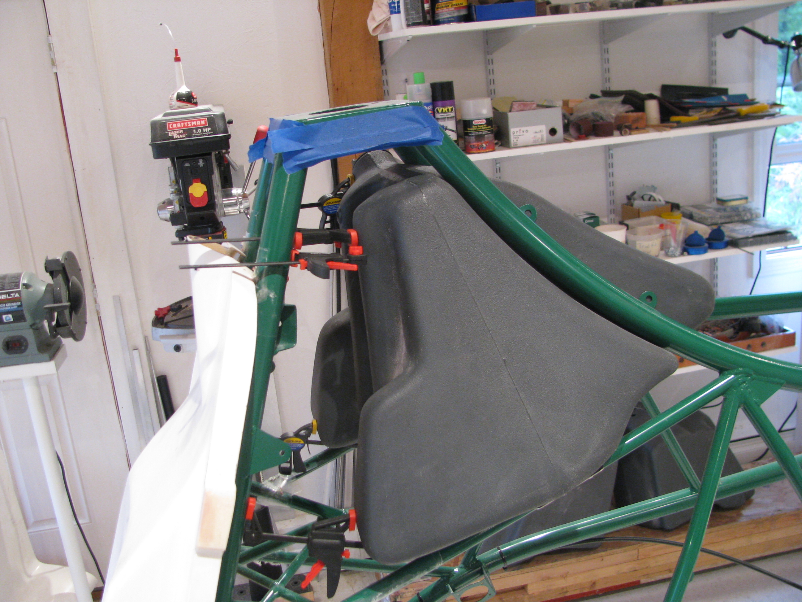
I set to work fabricating the hold-down straps for the aux tank. I didn’t like the way BJ called for the strap to be simply bent and bolted to the back of the seat. Seemed like there would be a stress point right at the bolt, so I riveted on a couple of pieces of angle to better handle the 90 degree force turn.

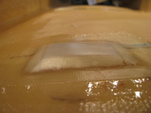
The curve of the seatback also caused the straps to not sit flat, so I glued on some foam strips, poured in some flox, ground and sanded them flat and perpendicular, then glassed over the foam.
The close up shows a tiny little void in the glass in the lower right, but this is non structural, so we won’t panic. I am learning fiberglass and my results are getting better, but I won’t be building a Long-EZ yet.
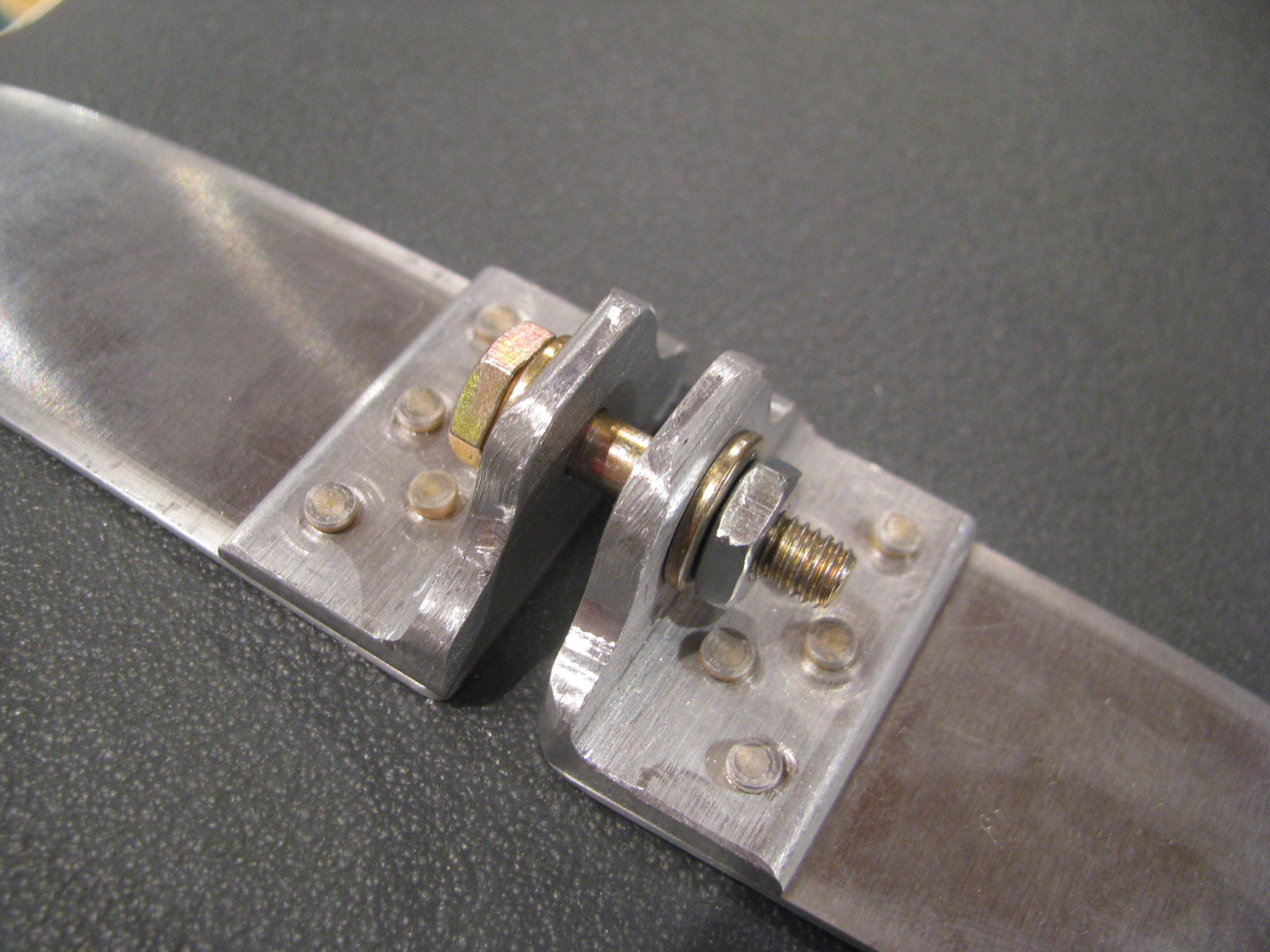
I whipped up these little brackets to allow for snugging down the straps and taking up any excess slack in the straps themselves. Not much weight and it should be easier to make sure we’re tight and not moving around at all.
Using BJs method would be lighter, but you’d have to have the strap length absolutely perfect to have them reach the correct tension right as they bottom out. Probably not possible with the flexing of the tank.
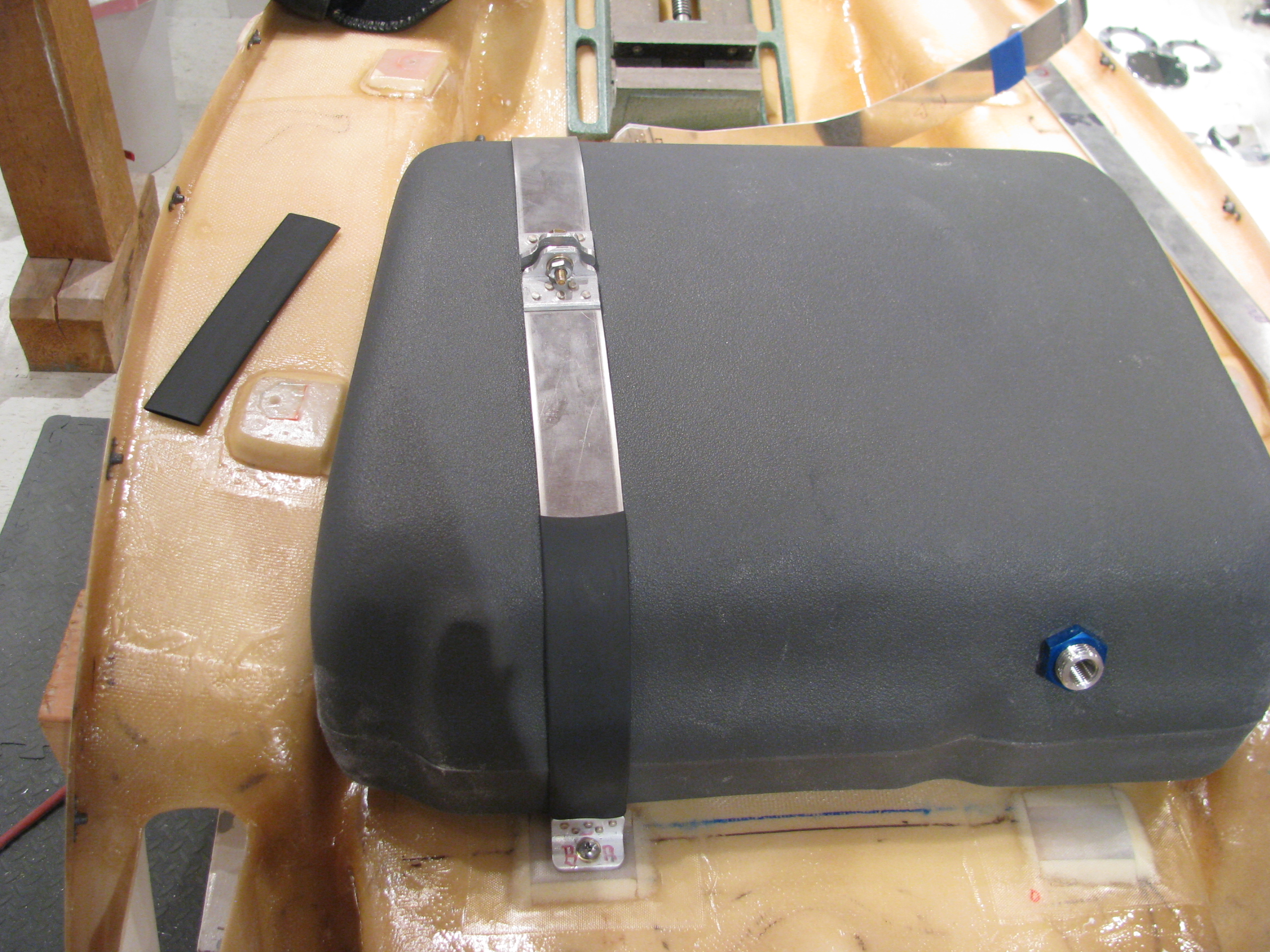
One down. One to go. I need more of this jumbo shrink tubing and to paint them up on completion.
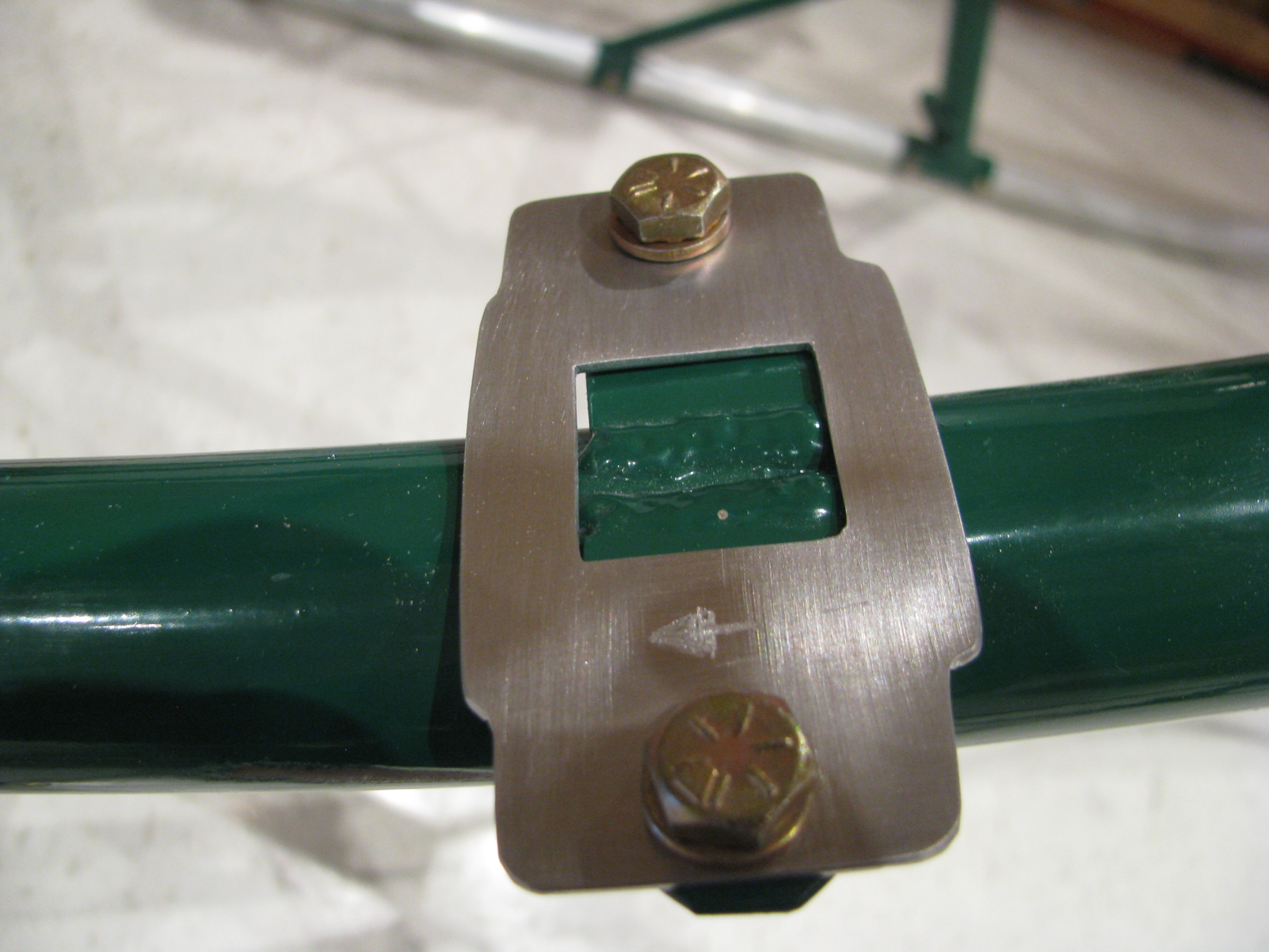
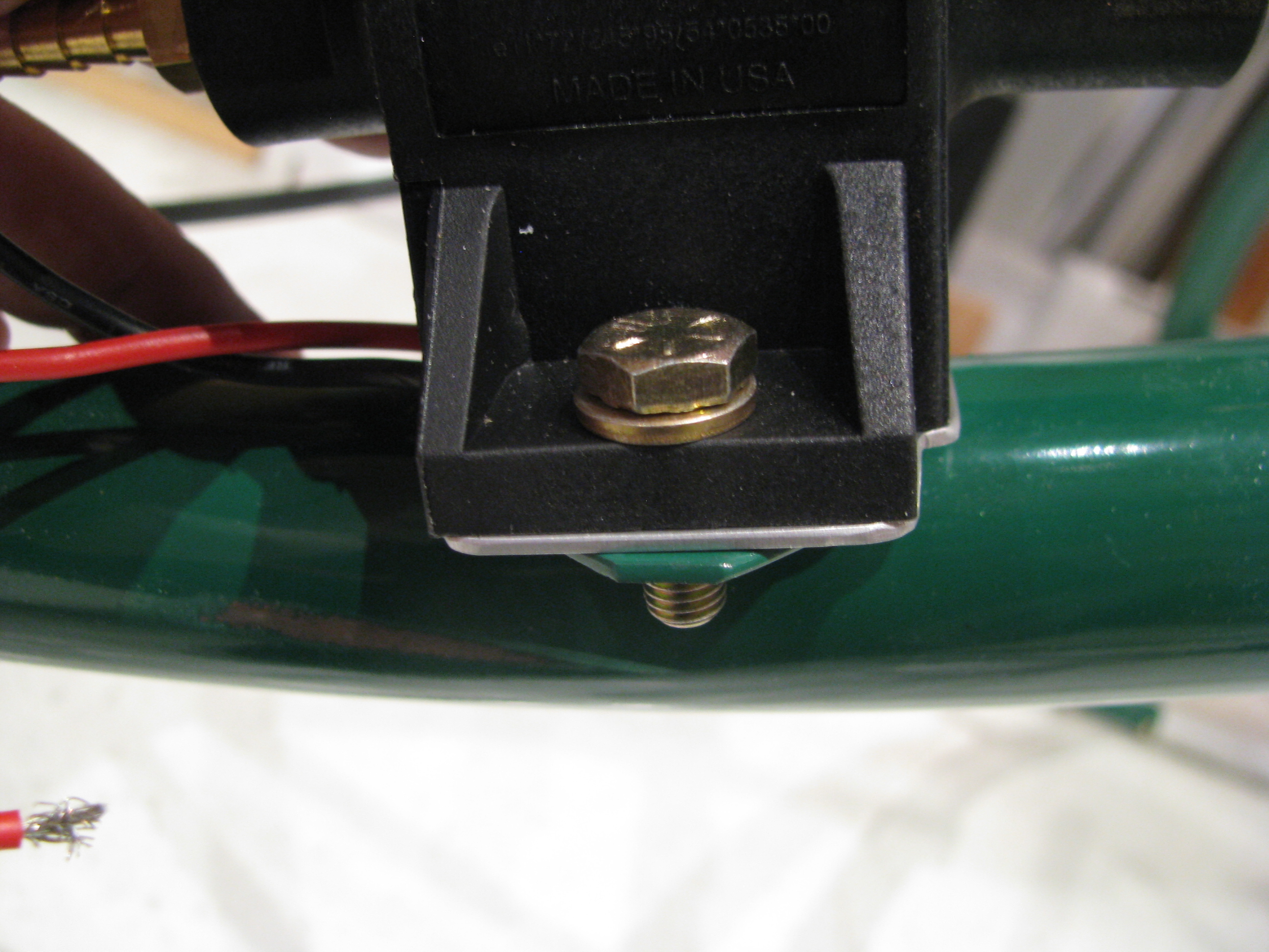
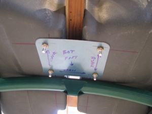
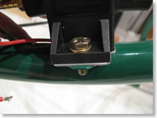
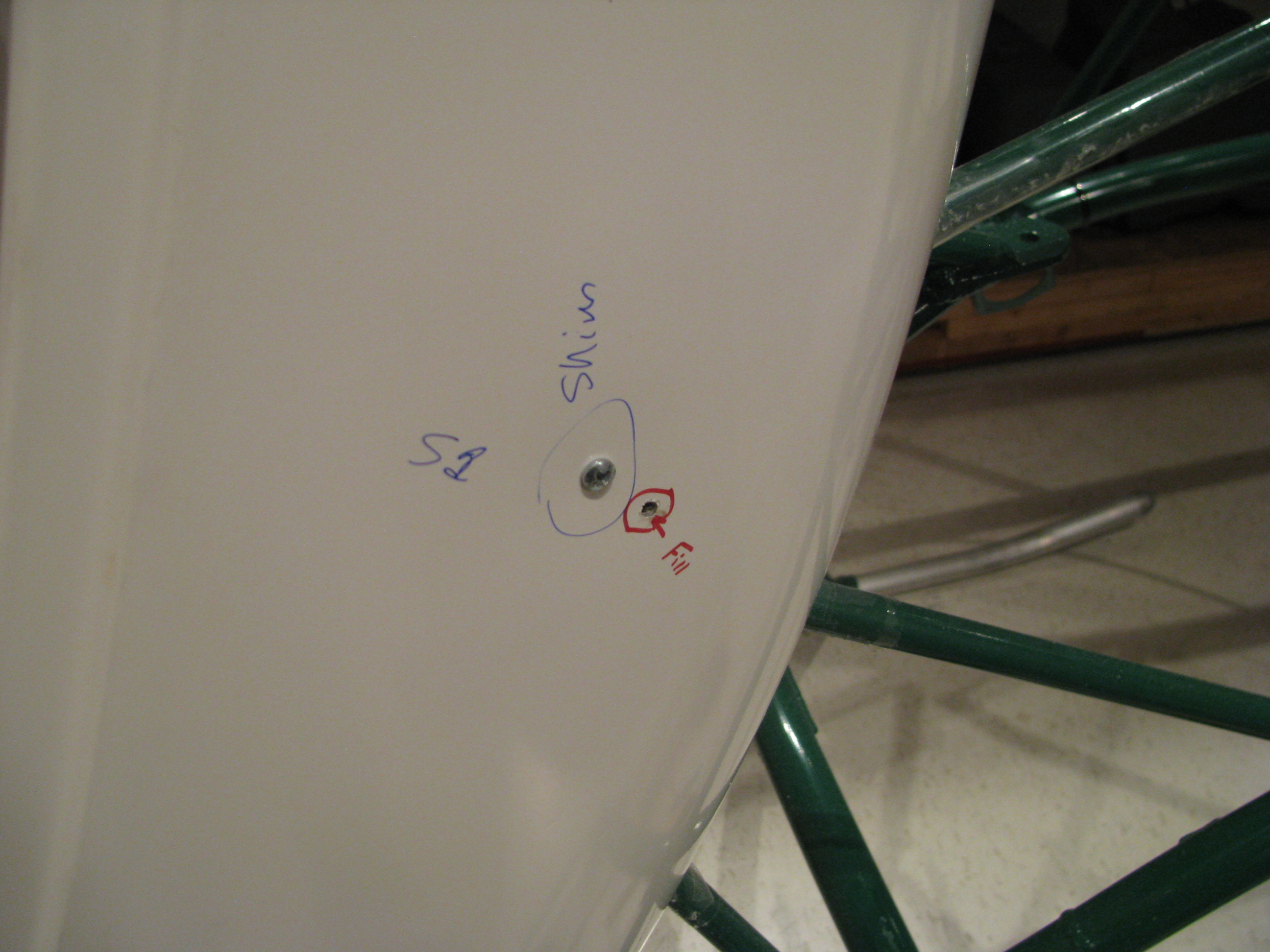
12/31/11 This is the fuel pump mount pad. The welds that mount the tabs to the frame extend up a little. Instead of grinding them down (weakening the joint and breaking the powdercoat) I just made this 0.050 shim in the shape fo the fuel pump base. It’s as thick as the welds and everything sits flat now.
Done for now. The tanks have been preliminarily fit, the hoses have been cut, and everything looks good. I have a fuel flow gauge and sender on order. When they get here I will seal it all up and do a leak check and be done with fuel until final assembly.
One note: I did elect to forego the Westberg sender and gauge since it seemed like a pretty expensive way to only measure the lower tank. I saw a video on the web of one builder who ran a sight gauge in the cockpit along the back interior edge of the seat pan. Pretty primitive, but an effective way to see the real level from the top to the bottom. I am thinking this is the way I’ll go as a gauge of last resort. The fuel flow meter will be primary with the visual sight level as backup.
Detail Fuel System Work
11/20/11 23:30 Filed in: All
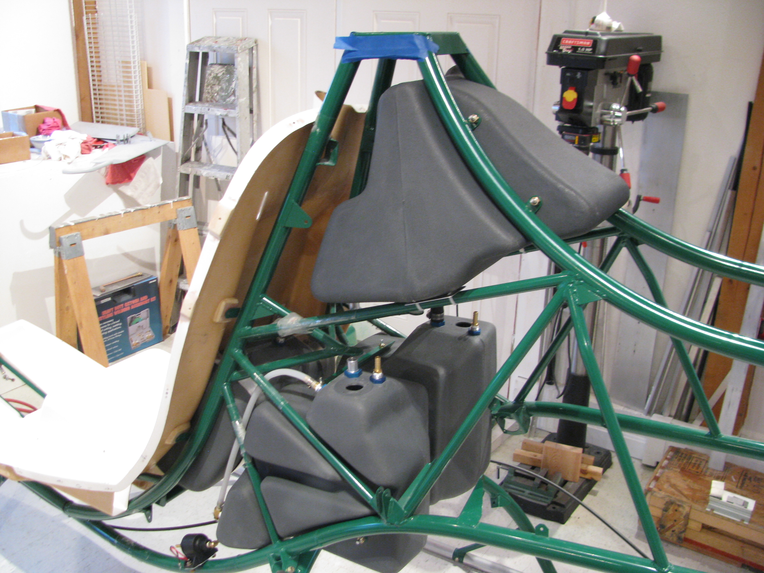
More fuel system detailed work. I fitted the tanks to the frame and drilled the appropriate mounting holes. This is not too demanding of a task, just a lot of little fitting and futzing. Of course the shape of the frame and the shape of the tanks is not super precise in the fashion in which they fit together, but it’s pretty close. I think the fuel system is a +/- 1/8” kind of precision as opposed to a 5mil kind of operation. EXCEPT the fittings. To be leak free these should be snug and tight fitting.
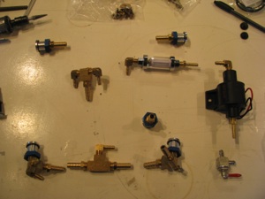
There are a lot of bits and pieces in many, many bags. I will admit that I did not inventory the fuel system when I took delivery of the kit, but everything seems to be there. So far the only thing I have been missing in the entire kit thus far has been one thin washer back in the mixer assembly.
The top tank is fitted out and drilled. I corked and checked for leaks with water. I plan on pre-assembling the entire fuel system in the ship and leak testing it in its entirety, then remove it all and then setting it aside until final assembly.
Fitting the lower tanks and drilling the spreader plates. I actually fished the little fittings through during the drilling op as they held the tanks more securely than just bolts pushed into position.
Plus, you’re doing this drilling upside down on your back, which is a little awkward.
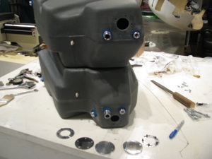
Fittings all installed in the lower tanks and the holes enlarged. I went ahead and drilled both cover plates. I do not plan on using the Westberg gauge and sender as I plan on using a fuel totalizer. In all the planes I have flown or owned I never use the fuel gauge. Time and total fuel actually used as reported by a totalizer has been far more accurate and reliable.
My Glasair gauges are useless as there is only a small band of gauge movement where they are actually in motion somewhere in the middle of the overall capacity. The totalizer is far more accurate.
Of course the thing you lose is the remote possibility of a catastrophic leak being detected in time to set it down before all fuel has leaked out. I’m willing to accept that.
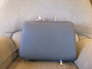
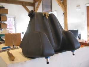
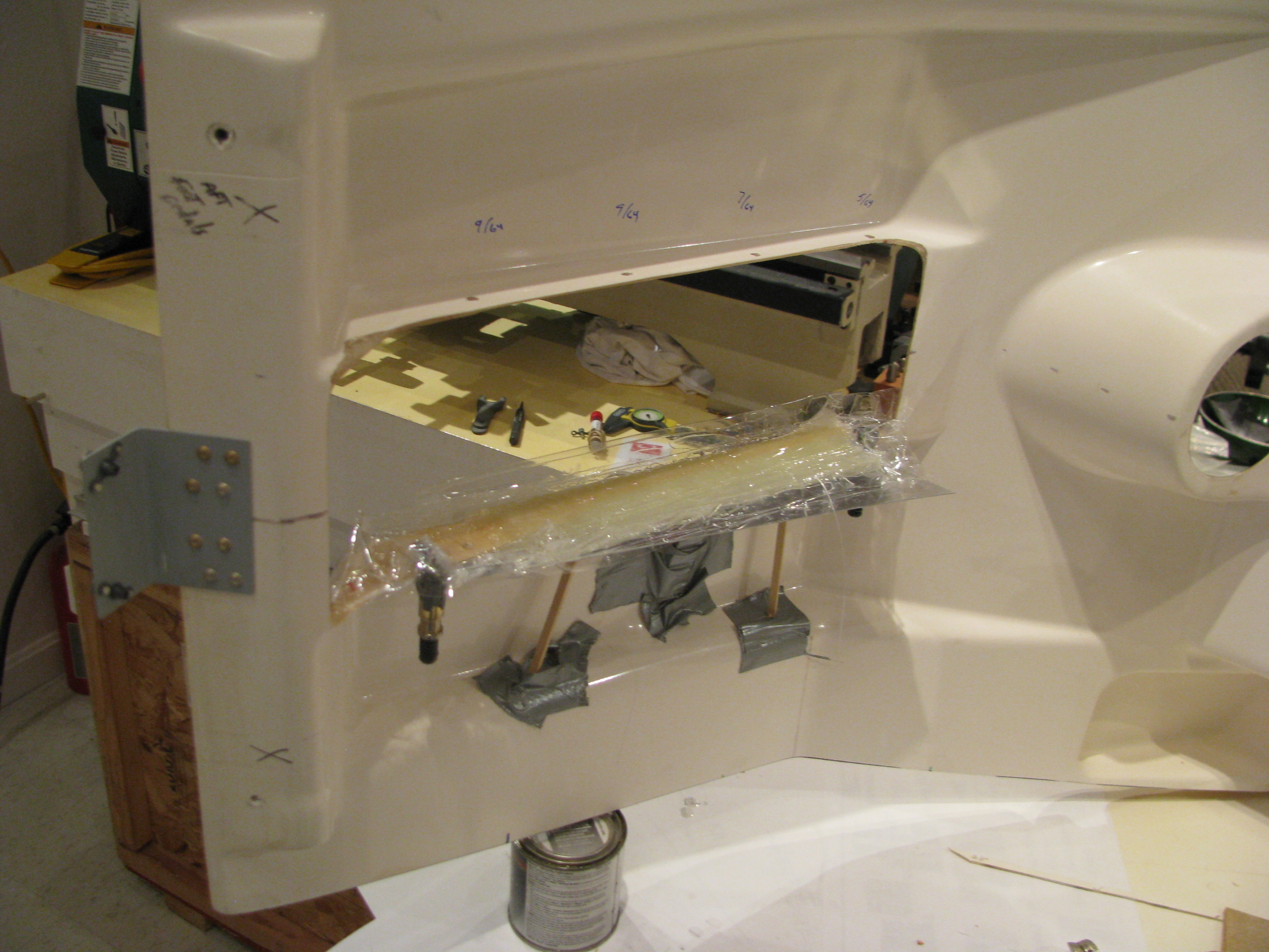
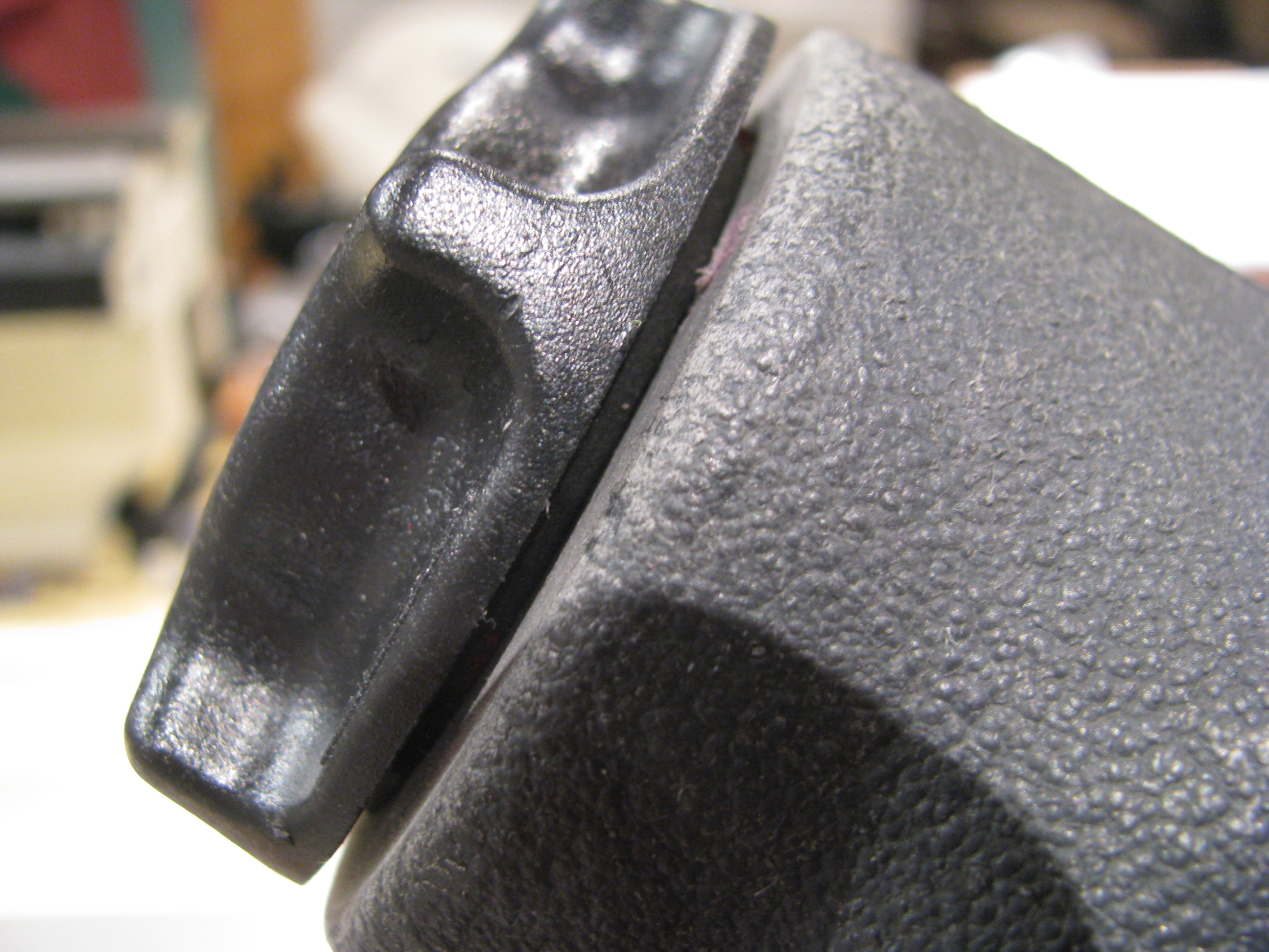
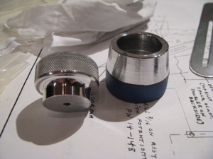
The aux tank is pretty easy. The only trick is that the upper opening (the large one) is not exactly a uniform cylinder. It took a bunch of sanding and trimming for the fitting to be persuaded in and to fit the O-ring securely.
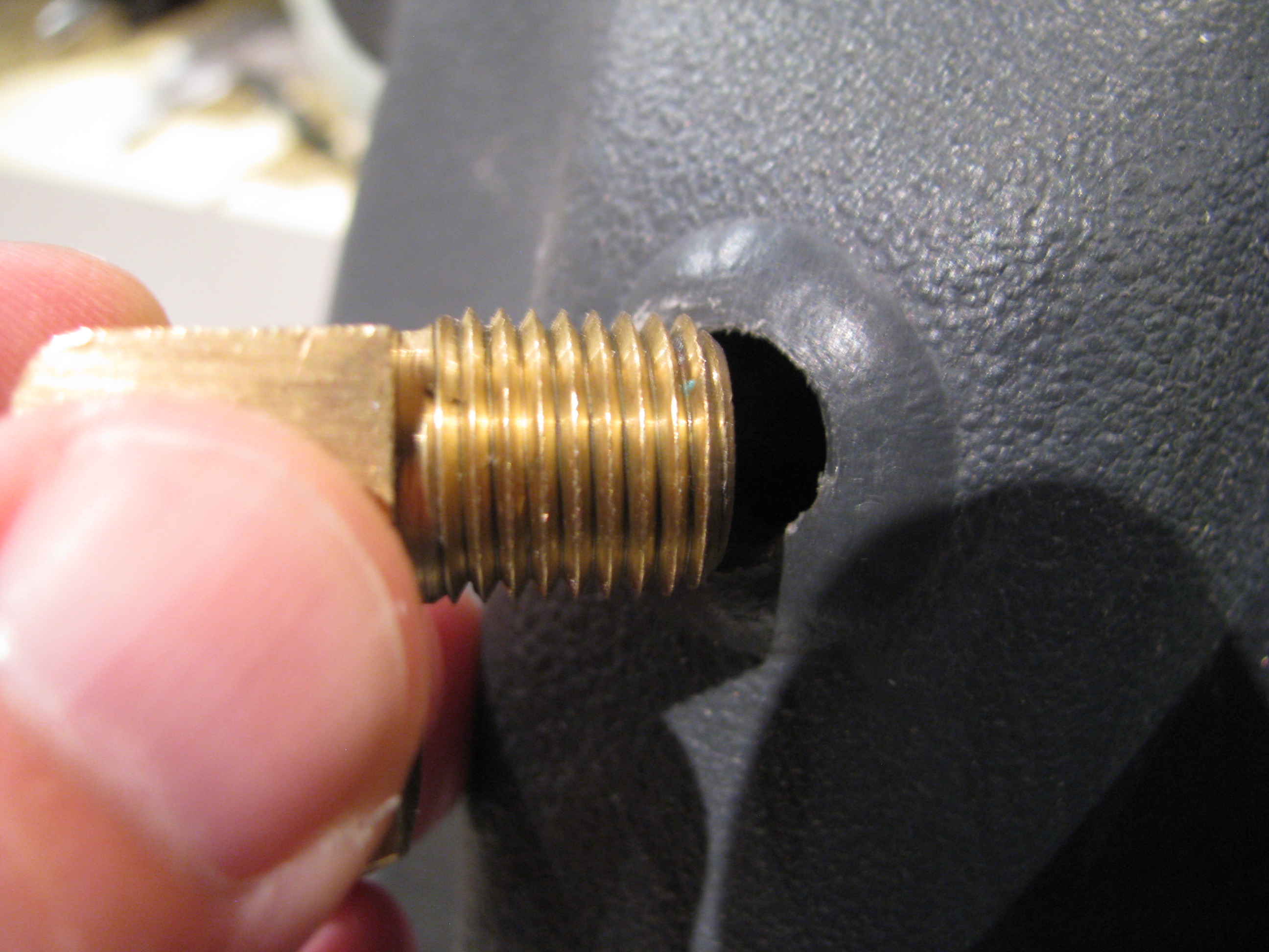
The only issue that bothers me is that in order to screw in the brass fittings I will probably have to clamp the external threads to hold the fittings steady, which is bound to bugger the threads. That will prevent the inserts from ever being removed.
12/1/11 - I set to work fabricating the hold-down straps for the aux tank. I didn’t like the way BJ called for the strap to be simply bent and bolted to the back of the seat. Seemed like there would be a stress point right at the bolt, so I riveted on a couple of pieces of angle to better handle the 90 degree force turn.
The curve of the seatback also caused the straps to not sit flat, so I glued on some foam strips, poured in some flox, ground and sanded them flat and perpendicular, then glassed over the foam.
The close up shows a tiny little void in the glass in the lower right, but this is non structural, so we won’t panic. I am learning fiberglass and my results are getting better, but I won’t be building a Long-EZ yet.
I whipped up these little brackets to allow for snugging down the straps and taking up any excess slack in the straps themselves. Not much weight and it should be easier to make sure we’re tight and not moving around at all.
Using BJs method would be lighter, but you’d have to have the strap length absolutely perfect to have them reach the correct tension right as they bottom out. Probably not possible with the flexing of the tank.

One down. One to go. I need more of this jumbo shrink tubing and to paint them up on completion.
12/31/11 This is the fuel pump mount pad. The welds that mount the tabs to the frame extend up a little. Instead of grinding them down (weakening the joint and breaking the powdercoat) I just made this 0.050 shim in the shape fo the fuel pump base. It’s as thick as the welds and everything sits flat now.
Done for now. The tanks have been preliminarily fit, the hoses have been cut, and everything looks good. I have a fuel flow gauge and sender on order. When they get here I will seal it all up and do a leak check and be done with fuel until final assembly.
One note: I did elect to forego the Westberg sender and gauge since it seemed like a pretty expensive way to only measure the lower tank. I saw a video on the web of one builder who ran a sight gauge in the cockpit along the back interior edge of the seat pan. Pretty primitive, but an effective way to see the real level from the top to the bottom. I am thinking this is the way I’ll go as a gauge of last resort. The fuel flow meter will be primary with the visual sight level as backup.

There are a lot of bits and pieces in many, many bags. I will admit that I did not inventory the fuel system when I took delivery of the kit, but everything seems to be there. So far the only thing I have been missing in the entire kit thus far has been one thin washer back in the mixer assembly.

The top tank is fitted out and drilled. I corked and checked for leaks with water. I plan on pre-assembling the entire fuel system in the ship and leak testing it in its entirety, then remove it all and then setting it aside until final assembly.

Fitting the lower tanks and drilling the spreader plates. I actually fished the little fittings through during the drilling op as they held the tanks more securely than just bolts pushed into position.
Plus, you’re doing this drilling upside down on your back, which is a little awkward.

Fittings all installed in the lower tanks and the holes enlarged. I went ahead and drilled both cover plates. I do not plan on using the Westberg gauge and sender as I plan on using a fuel totalizer. In all the planes I have flown or owned I never use the fuel gauge. Time and total fuel actually used as reported by a totalizer has been far more accurate and reliable.

My Glasair gauges are useless as there is only a small band of gauge movement where they are actually in motion somewhere in the middle of the overall capacity. The totalizer is far more accurate.
Of course the thing you lose is the remote possibility of a catastrophic leak being detected in time to set it down before all fuel has leaked out. I’m willing to accept that.
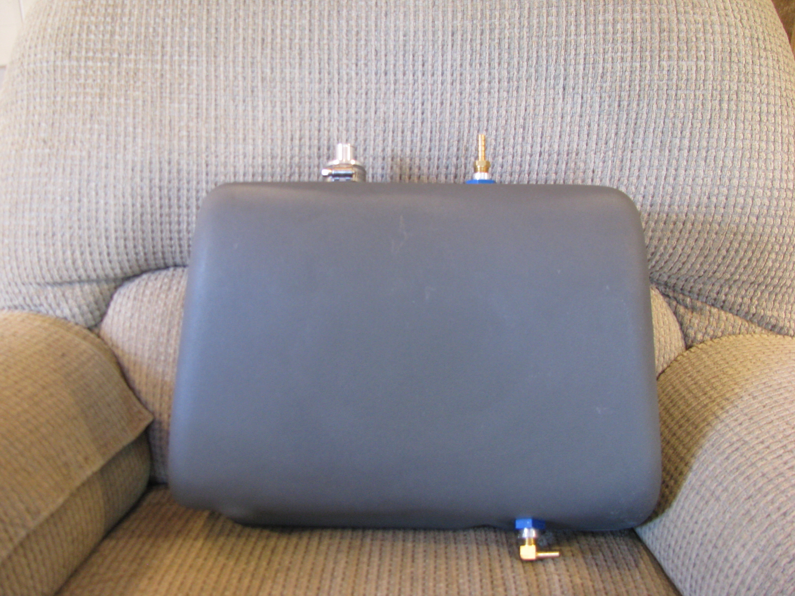
The aux tank is pretty easy. The only trick is that the upper opening (the large one) is not exactly a uniform cylinder. It took a bunch of sanding and trimming for the fitting to be persuaded in and to fit the O-ring securely.
The only issue that bothers me is that in order to screw in the brass fittings I will probably have to clamp the external threads to hold the fittings steady, which is bound to bugger the threads. That will prevent the inserts from ever being removed.
12/1/11 - I set to work fabricating the hold-down straps for the aux tank. I didn’t like the way BJ called for the strap to be simply bent and bolted to the back of the seat. Seemed like there would be a stress point right at the bolt, so I riveted on a couple of pieces of angle to better handle the 90 degree force turn.
The curve of the seatback also caused the straps to not sit flat, so I glued on some foam strips, poured in some flox, ground and sanded them flat and perpendicular, then glassed over the foam.
The close up shows a tiny little void in the glass in the lower right, but this is non structural, so we won’t panic. I am learning fiberglass and my results are getting better, but I won’t be building a Long-EZ yet.
I whipped up these little brackets to allow for snugging down the straps and taking up any excess slack in the straps themselves. Not much weight and it should be easier to make sure we’re tight and not moving around at all.
Using BJs method would be lighter, but you’d have to have the strap length absolutely perfect to have them reach the correct tension right as they bottom out. Probably not possible with the flexing of the tank.
One down. One to go. I need more of this jumbo shrink tubing and to paint them up on completion.
12/31/11 This is the fuel pump mount pad. The welds that mount the tabs to the frame extend up a little. Instead of grinding them down (weakening the joint and breaking the powdercoat) I just made this 0.050 shim in the shape fo the fuel pump base. It’s as thick as the welds and everything sits flat now.
Done for now. The tanks have been preliminarily fit, the hoses have been cut, and everything looks good. I have a fuel flow gauge and sender on order. When they get here I will seal it all up and do a leak check and be done with fuel until final assembly.
One note: I did elect to forego the Westberg sender and gauge since it seemed like a pretty expensive way to only measure the lower tank. I saw a video on the web of one builder who ran a sight gauge in the cockpit along the back interior edge of the seat pan. Pretty primitive, but an effective way to see the real level from the top to the bottom. I am thinking this is the way I’ll go as a gauge of last resort. The fuel flow meter will be primary with the visual sight level as backup.
More Training Toward Ticket
11/20/11 21:48 Filed in: All
11/20/11 - Still slow. Lots of work travel. Two trips to California, Miami, Norfolk, Atlanta, Pittsburgh, and more I have probably forgotten. Maybe three more sessions before the checkride. Looks like the first or second week of December. I did probably my best straight-in and then a 180 auto today. Feeling pretty comfortable in a helo at this point and it is still intensely cool.
Still Training
10/20/11 21:46 Filed in: All
10/10/2011 - Well, things have slowed down with the Fall. I WAS at Reno. Yes, Reno where the Galloping Ghost had his mishap. I certainly hope that I did not witness the last lap to be raced at Reno. That’s a story that deserves its own page, not this one.
Two weeks of rain followed and there goes a whole month without flying a helicopter. I got up this weekend, but am off to Taiwan next week, so who knows how much longer this will drag on. Halloween was the target. Maybe Thanksgiving at this rate.
Two weeks of rain followed and there goes a whole month without flying a helicopter. I got up this weekend, but am off to Taiwan next week, so who knows how much longer this will drag on. Halloween was the target. Maybe Thanksgiving at this rate.
Chin Window Drilling & Cabin Fiberglass
10/11/11 22:50 Filed in: All
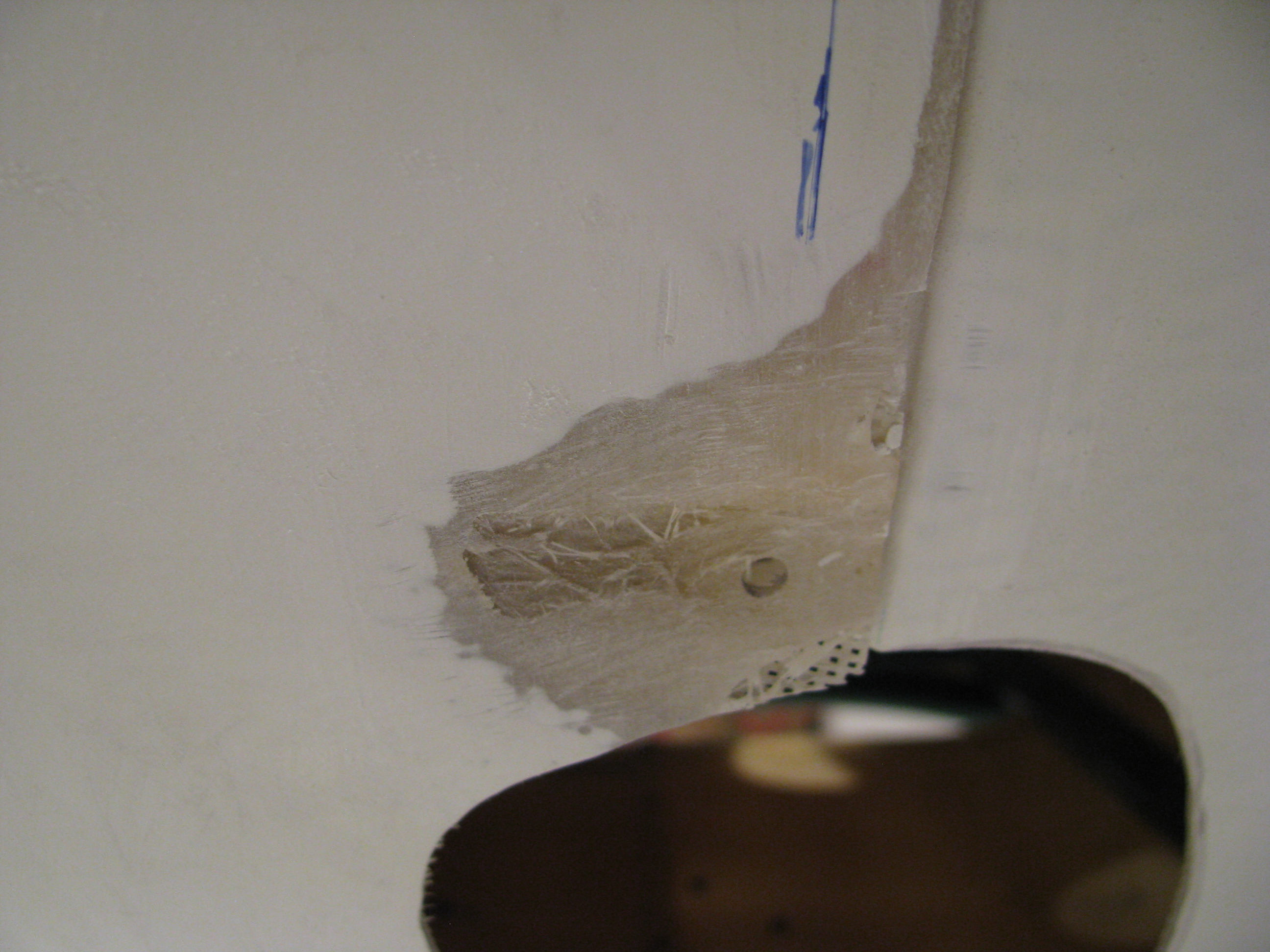
Cleaning up a lot of little things. Here is a spot on the body that was bubbled and mostly gelcoat. Ground it out, heat and flattened the fiberglass with a heatgun and pressed it between some angle to straighten . Finally layed up a couple of thin layers to add strength and bondoed to smooth it out.
There were a couple of spots that required this treatment.
Here is where the pre-drilled holes didn’t quite line up with where the floorpan actually fell. Had to drill a new one and fill the old.

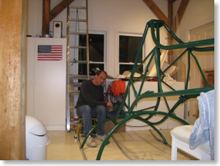
FAA required picture of me working. Gotta remember to get more of these. Since I am usually working alone it means getting out the tripod and setting up the camera timer. Coffee fueled build process.
Holes are easy to drill, but each one needs a nutplate and there sure are a lot of them. Here I am drilling and mounting the chin window floating nutplates.
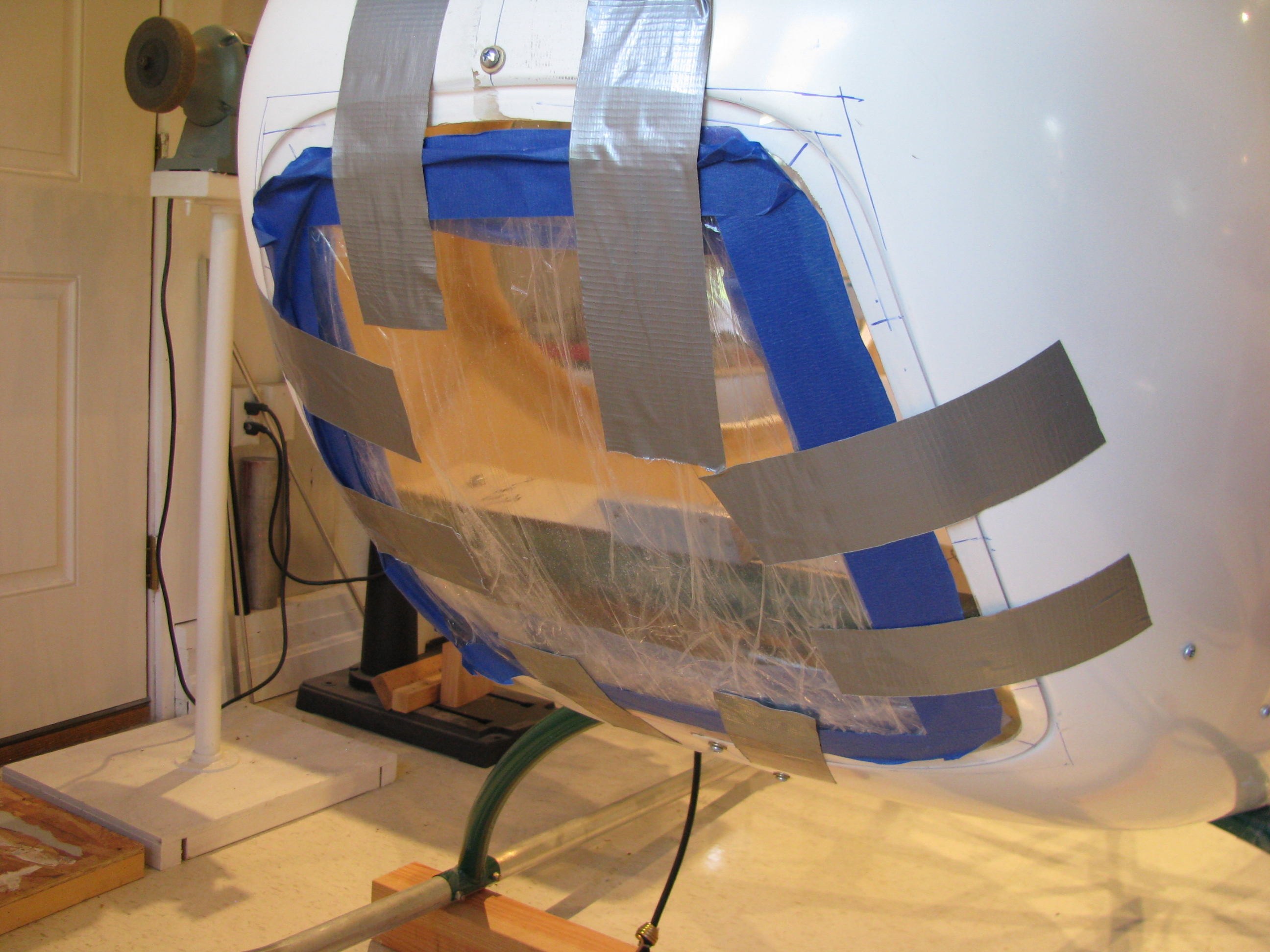
There’s a lot more fiberglass work than I anticipated. This is the lip of the floorpan along the base of the instrument pod. The drilled holes cut through the edge of the lip.
I had to first cut away the fiberglass with the partial holes. A dam was built with packing tape and a tape covered aluminum sheet. Then an thin layer of flox to allow the edge to form, then five layers of cloth. I’ll have to sand a lot of it down, but it should allow for a tight fit with plenty of meat around the holes. It’ll be a lot “taller” than the original lip.

In a few places I had to shim the pan, especially up around the curve of the top of the body. A layer of foam sanded to the correct thickness, then glassed over. To mount the nutplates behind the lip I had to cut a strip of aluminum, mount the nutplate, then rivet it outside the foamed area.
Initial Fuel System Work
10/10/11 23:07 Filed in: All

The fuel system on a Helicycle is relatively complex compared to “normal” aircraft. There are a couple of reasons for this. First, the turbine is very thirsty and needs large capacity. Second, the fuel must be centered on or near the CG since this is a light, single-place machine.
Consequently, there are four different tanks and the associated plumbing and interconnect. Management is easy, though. Since everything gravity feeds to the lowest point where the pickup resides, there is no switching or pilot involvement required other than making sure you don’t run out.
The first thing BJ has you do is to file a bit off the cap threads to allow it to screw in snugly, but smoothly. Easy and quick.
Next is to file the gasket area flush for a good seal. The tank is relatively thin, so don’t be ham handed with the sanding.
A lot of guys seem to modify the gas cap area to allow for better Jet-A fueling options. Maybe I will too, but not until the machine is built to the plans first. Gotta finish, then modify.
Next is fitting the air vent street elbow. There was no way mine was going to fit, so the next time I was at Harbor Freight I picked up a 1/4” NPT tap ($6 for a set of three- amazing).
Just tap enough to get it started (maybe one turn), otherwise it’ll probably be too much. The threaded area is pretty thin overall.
Quick Clamps with the jaws reversed so that they “separate” instead of “clamp” seem to work well to shove the tank back up against the frame tubes in preparation for drilling the mounting holes.
BJ has the tank base plates just tie-wrapped on. Even my dad thought that looked chinzy, so I may end up doing something beefier before final installation.


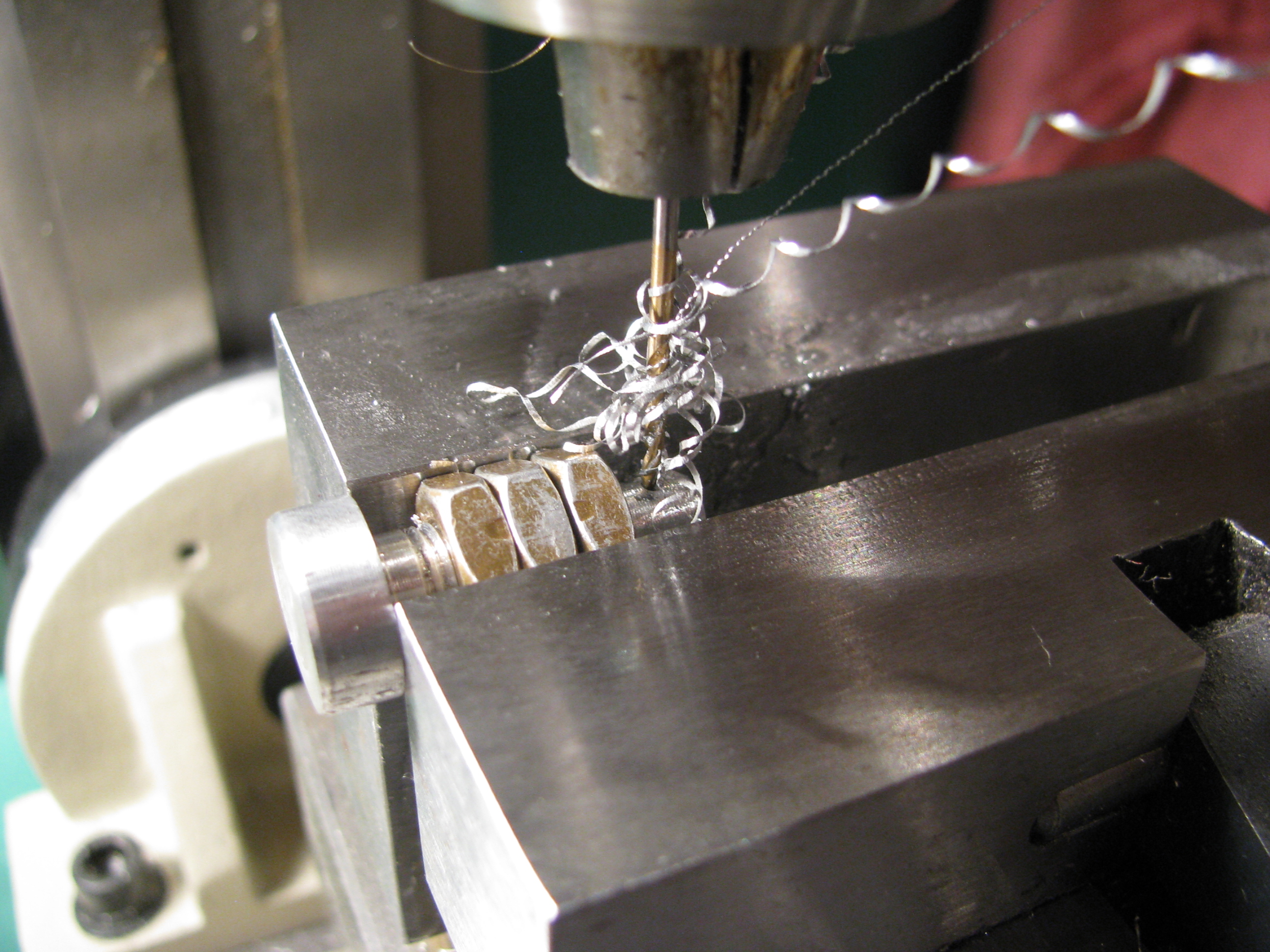
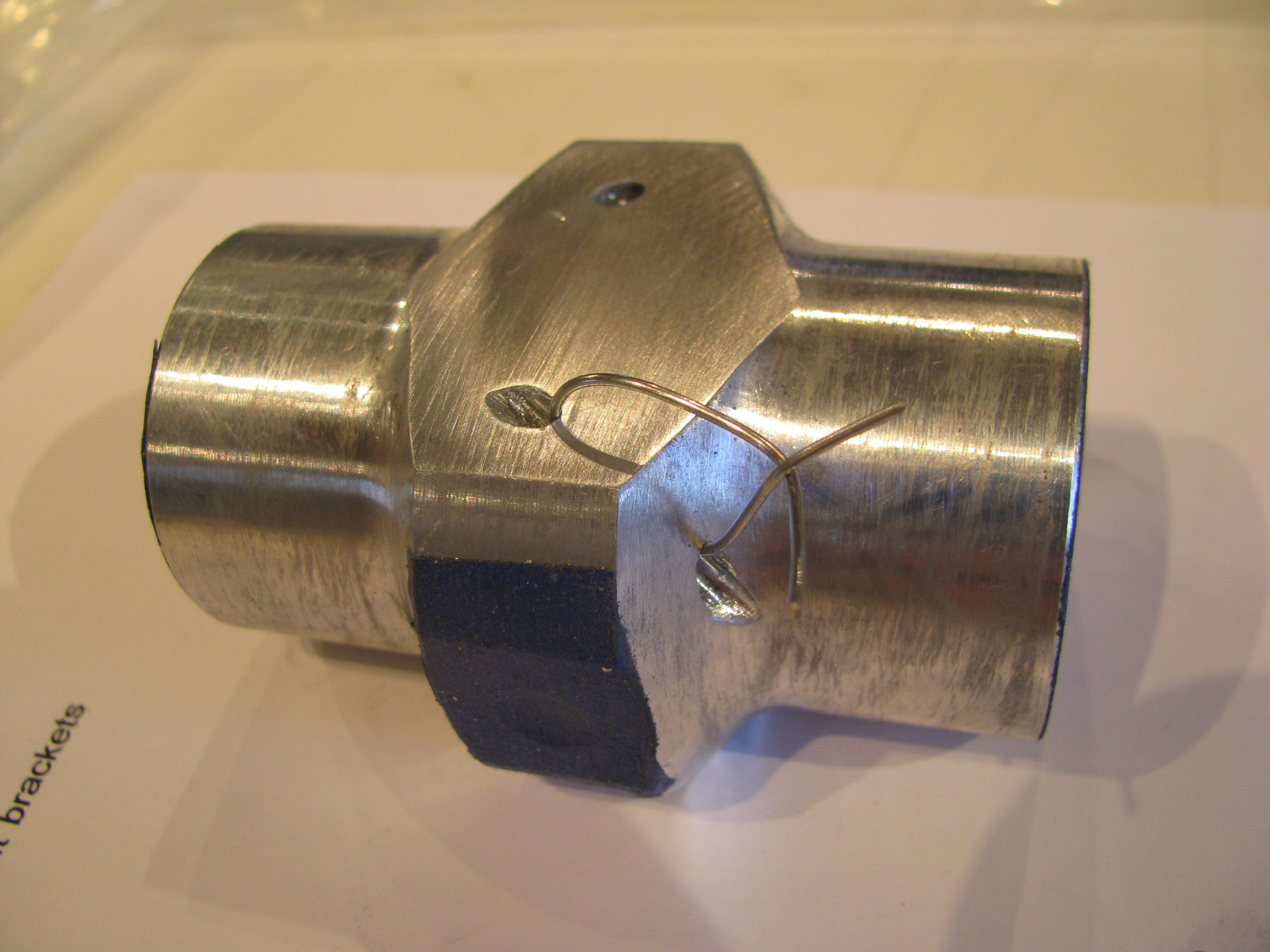
The machined tank mount bolt plugs were a little snug for the nuts. They had to be cleaned up with a 5/16-24 die, then the holes for the “fishing wire” drilled into the end portion. Another ad for the mill/drill. Quick and easy to center the holes. And of course a picture of me for the FAA.
Slogging Through Requirements
09/05/11 21:44 Filed in: All
At this point I have been slogging through the requirements and am just about done.
10 hours solo with 3 of cross country. 3 hours night time. Night cross country. Controlled traffic patterns. Pinnacles. Confined Areas. Slopes. Autos. Autos. Autos. 3 hours checkride prep. Now it’s time to hit the books and maybe put in another 2 hours to sharpen everything up and hit my spots. Then we’ll see how it goes. I had hoped to have this done by Reno, but maybe by Halloween.
10 hours solo with 3 of cross country. 3 hours night time. Night cross country. Controlled traffic patterns. Pinnacles. Confined Areas. Slopes. Autos. Autos. Autos. 3 hours checkride prep. Now it’s time to hit the books and maybe put in another 2 hours to sharpen everything up and hit my spots. Then we’ll see how it goes. I had hoped to have this done by Reno, but maybe by Halloween.
Drilling Windscreen & Bodywork
08/11/11 22:46 Filed in: All
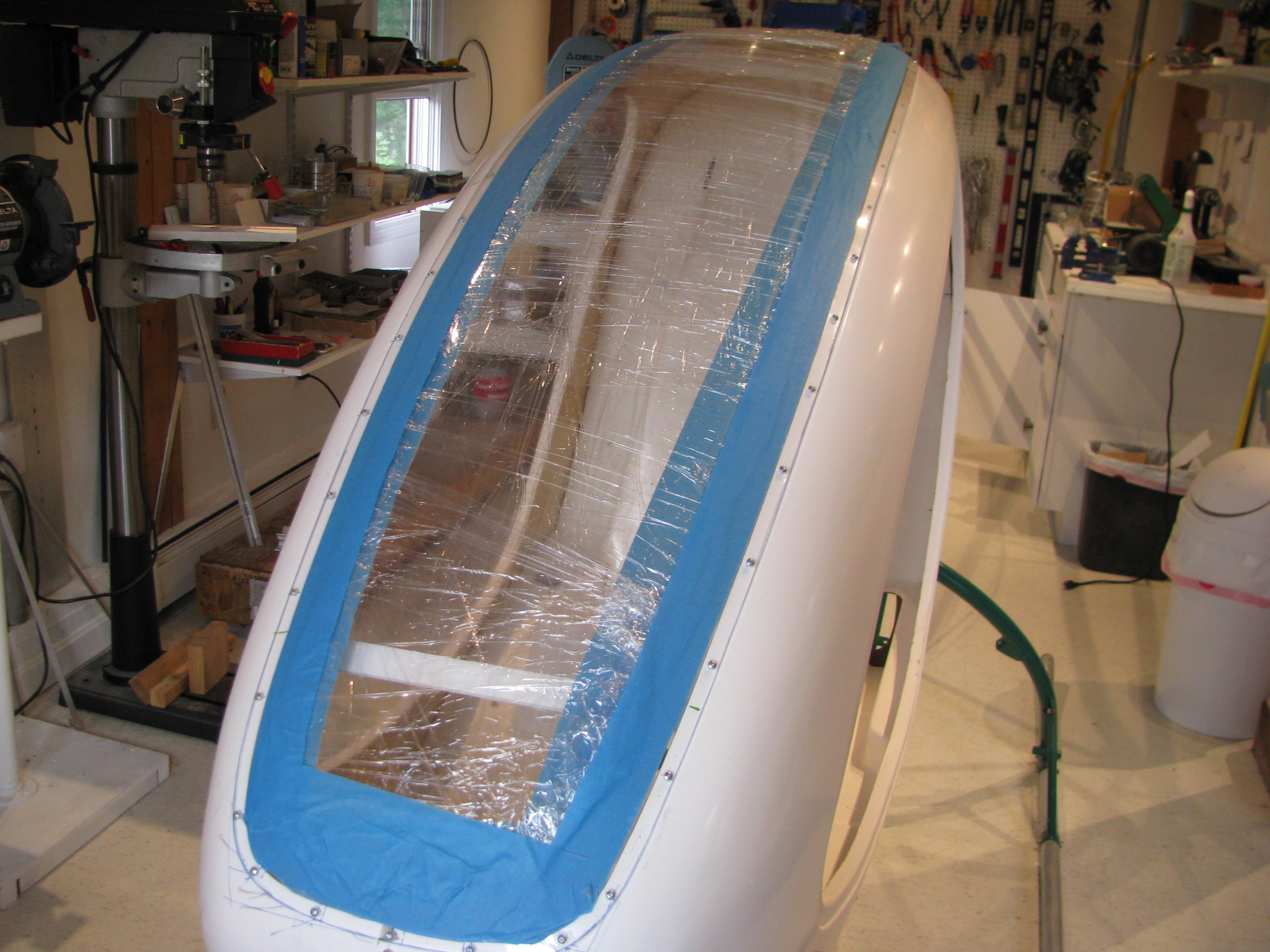
It’s been a few weeks with slow progress. I fitted and trimmed the windscreen and lower plexi and drilled them to the frame.
The windscreen and lower window really add a lot of strength to the cabin. It’s pretty solid now. My shop was about 90 degrees, so the plexi was pretty flexible and the holes drilled cleanly. Only a few will need some sanding and beveling as there looks to be a chip or two on the backside.
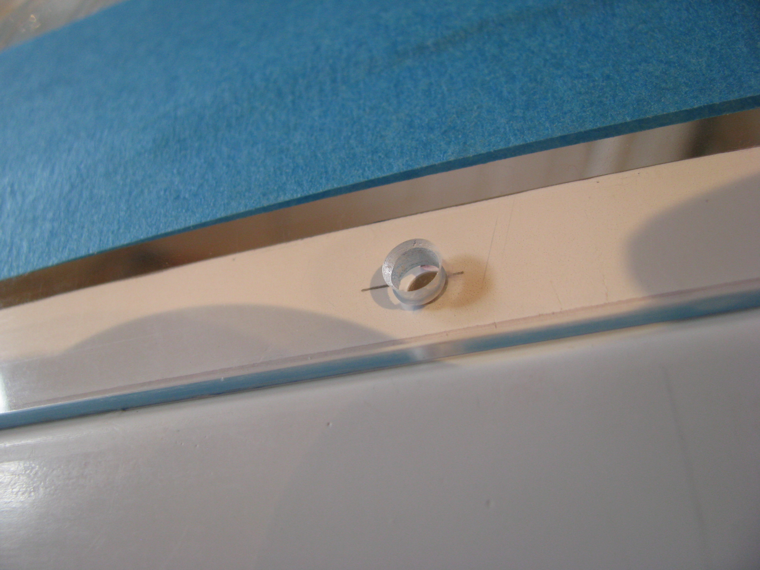
Most of the holes look like this after drilling and beveling. Overall I am pleased with the result
Initial Screen Fitting
07/22/11 22:39 Filed in: All
Lower plexi taped in place on front. Lot’s of trimming to fit the joggle cleanly. It has been drilled and I purchased a bunch of #6 floating nutplates after having read the experiences of others. Apparently with the instrument cluster in place there is almost no way to get your hands in there to place acorn nuts.
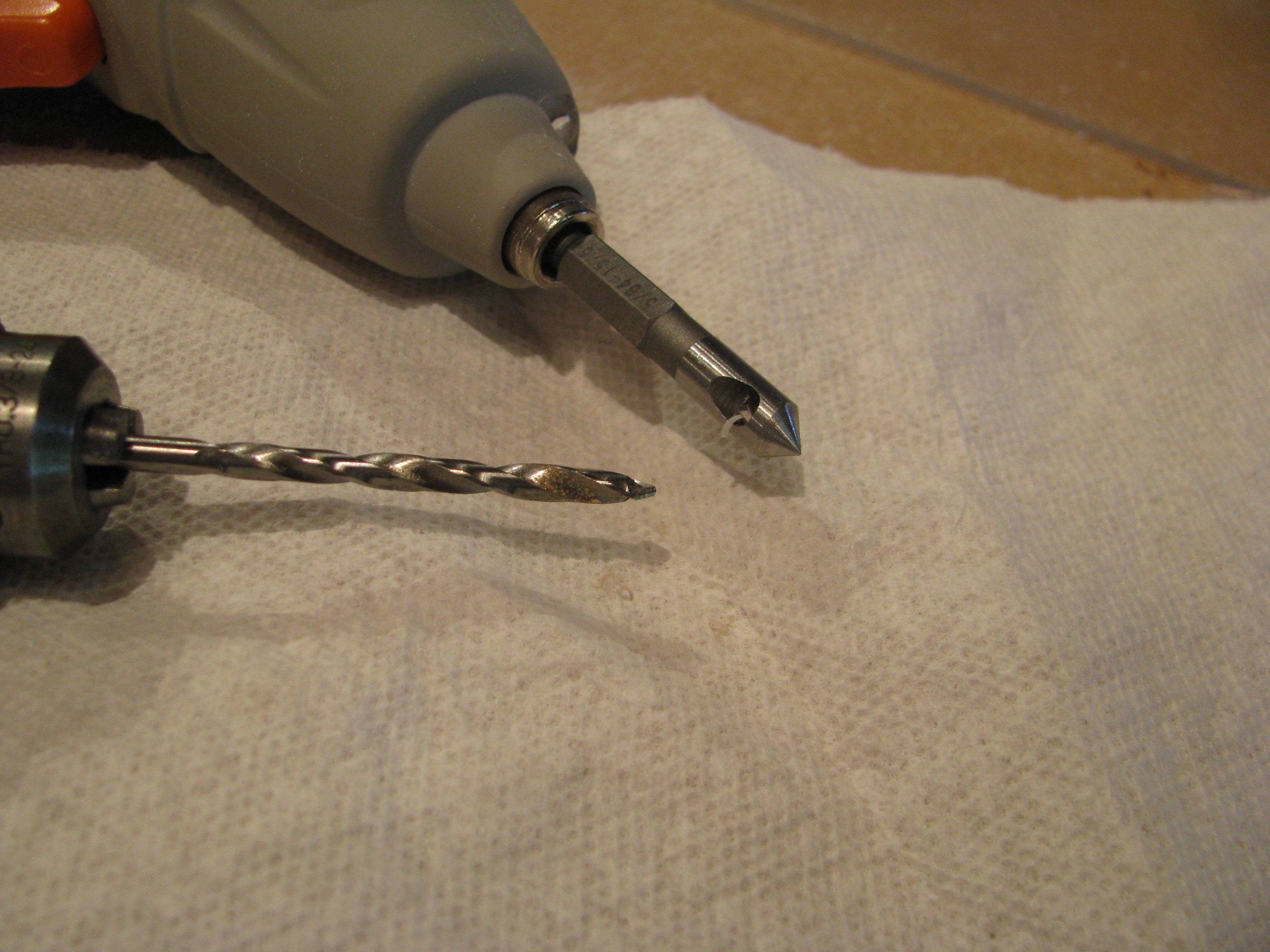
Here is my dynamic duo for drilling the plexi. The drill bit is a #27 plexi bit from Avery Tool. It has a shallow cutting 60 degree point. The countersink I picked up from the sale bin at Harbor Freight. It has a single flute and just barely shaves, which leaves a nice, chatter-free chamfer on the plexi holes. $3.99 for a set of three. It would probably dull immediately on aluminum or steel, but it’s great for this application.

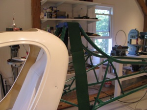
The windscreen opening is pretty floppy without the windscreen. I hot glued some foamcore “I-beams” to hold the width to almost exactly match the windscreen. Makes fitting and holding the windscreen in place much easier. I thought peeling the hotglue out would be easy when I’m done, but I tried peeling off a blob and it really, really grips that rough fiberglass pretty securely in fact. Oh well.
Drilling Cabing Halves
07/18/11 22:26 Filed in: All
Spotty progress due to work travel. Two trips to Mexico and one to California. Enough excuses - I tweaked the seatpan mounts as much as I could to get the body to fit better. The two rearmost pre-drilled holes on the left side won’t work no matter what I do, though, so they have been repositioned about an inch forward. The existing holes will be filled.

Body halves drilled all around. Straps, cleco clamps, and an extra pair of hands helps here a lot There are really no straight lines or easy reference points to tell whether it’s square and symmetric. Lots of fitting, standing back and eyeballing, then tweaking to make it as square as possible. About 14 or 15 screws from the front to the seatpan top curve. I’ll shim and drill the very top of the seatpan curve once the windscreen is in place.

Rear of the body. The cutouts don’t match exactly, but that’s OK. I’ll trim them in place.
I found some green felt that is a very good match to the frame powder coat color. I will use some spray adhesive and use that on the body shell interior when I get to that point.
Body halves drilled all around. Straps, cleco clamps, and an extra pair of hands helps here a lot There are really no straight lines or easy reference points to tell whether it’s square and symmetric. Lots of fitting, standing back and eyeballing, then tweaking to make it as square as possible. About 14 or 15 screws from the front to the seatpan top curve. I’ll shim and drill the very top of the seatpan curve once the windscreen is in place.
Rear of the body. The cutouts don’t match exactly, but that’s OK. I’ll trim them in place.
I found some green felt that is a very good match to the frame powder coat color. I will use some spray adhesive and use that on the body shell interior when I get to that point.
First Cabin Fit
06/21/11 22:21 Filed in: All
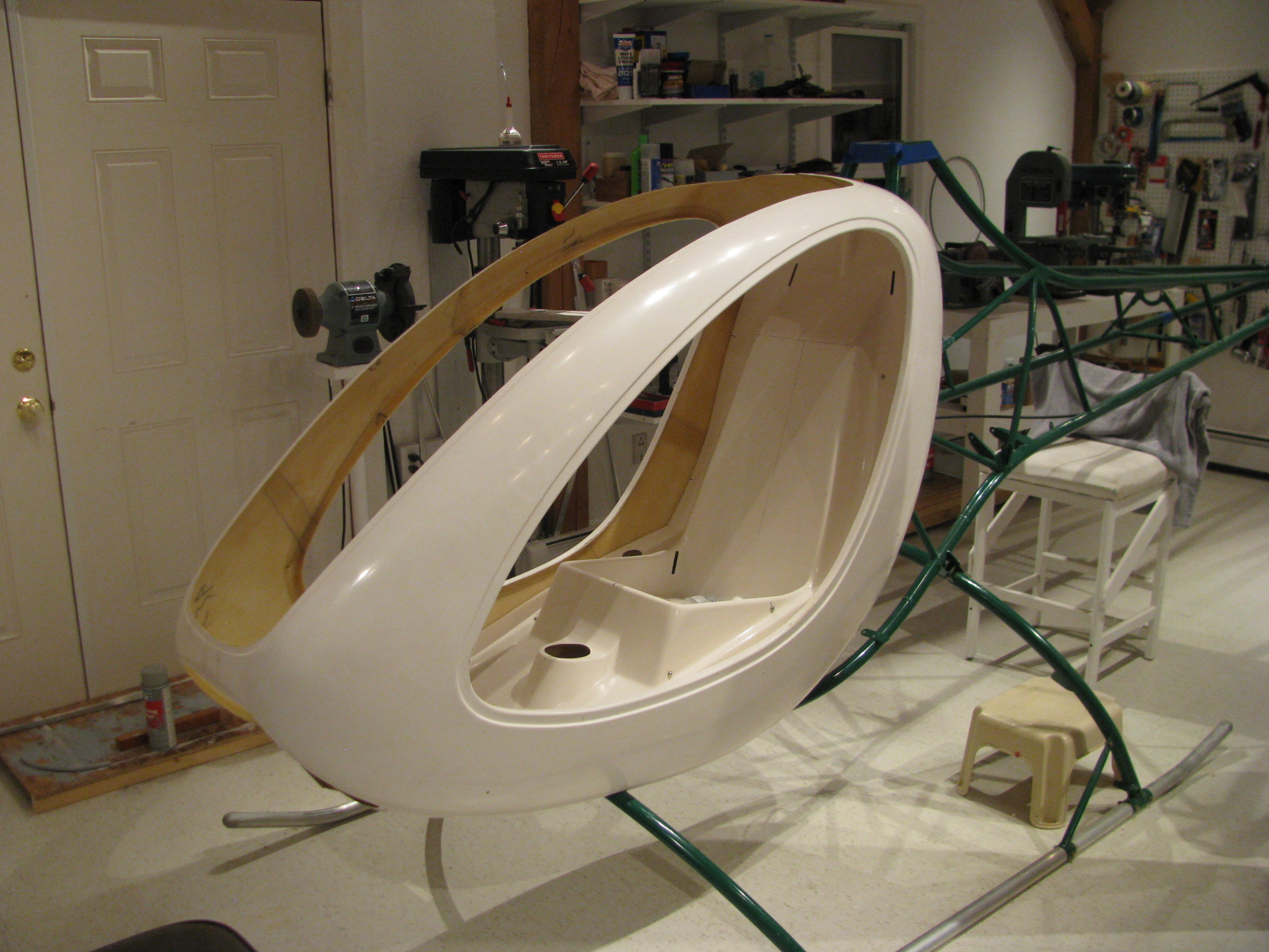
First fitting of the body halves. Of course they had to come off and on about a half dozen times to fine tune the cutouts around the body tubes. The powder coat on the body tubes got fairly scratched up in a few places before I had them all taped up to protect them, I’ll have to get some touch up paint of the same color.
The fit is pretty poor. I think my seatpan sits forward perhaps too much which makes the vertical holes on the sides impossible to line up on the left side without really deforming the seatpan. I may have to pull it all apart and redo the seat pan mounts so everything fits more cleanly. Darn. I thought this was going to be an easy bit.
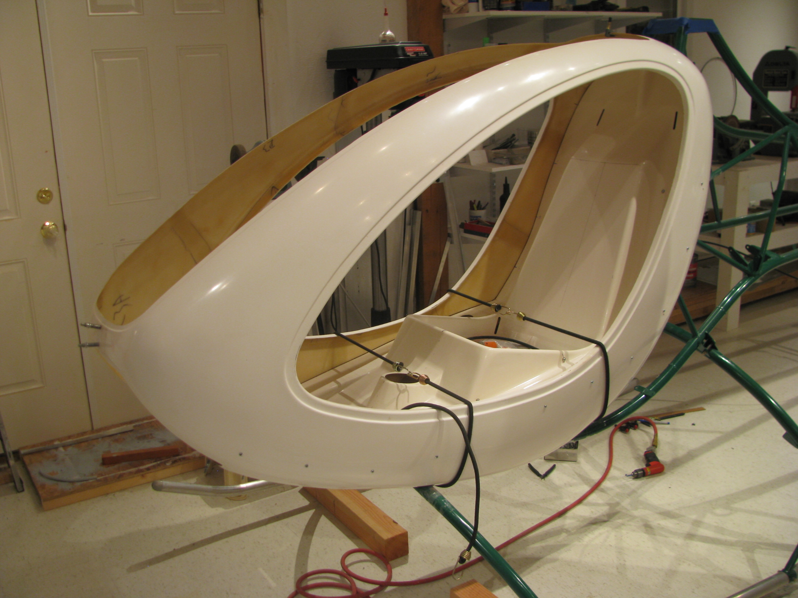
Anyway, it really looks like a flying machine with the body attached and I had to strongly resist the urge to climb in, make airplane noises, and daydream. The frame came powder coated dark green. I had been thinking dark yellow for the body, but perhaps a very stark white would work with polished skids and blades and grey Zolotone on the interior. Too soon??
Instrument Pod Bracket
06/19/11 22:15 Filed in: All
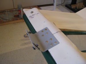
The front bracket is riveted on to stabilize the instrument pod. I have a lot of solid rivets in stock from my RV project and use them wherever possible instead of pop rivets.
Pan Drilling
06/15/11 22:06 Filed in: All
Finally got around to drilling the pan to the frame. It took a little more flox and some sanding to get things perfectly level and the tabs in place without much bending of the tabs (only a couple needed very minor tweaking).
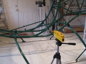
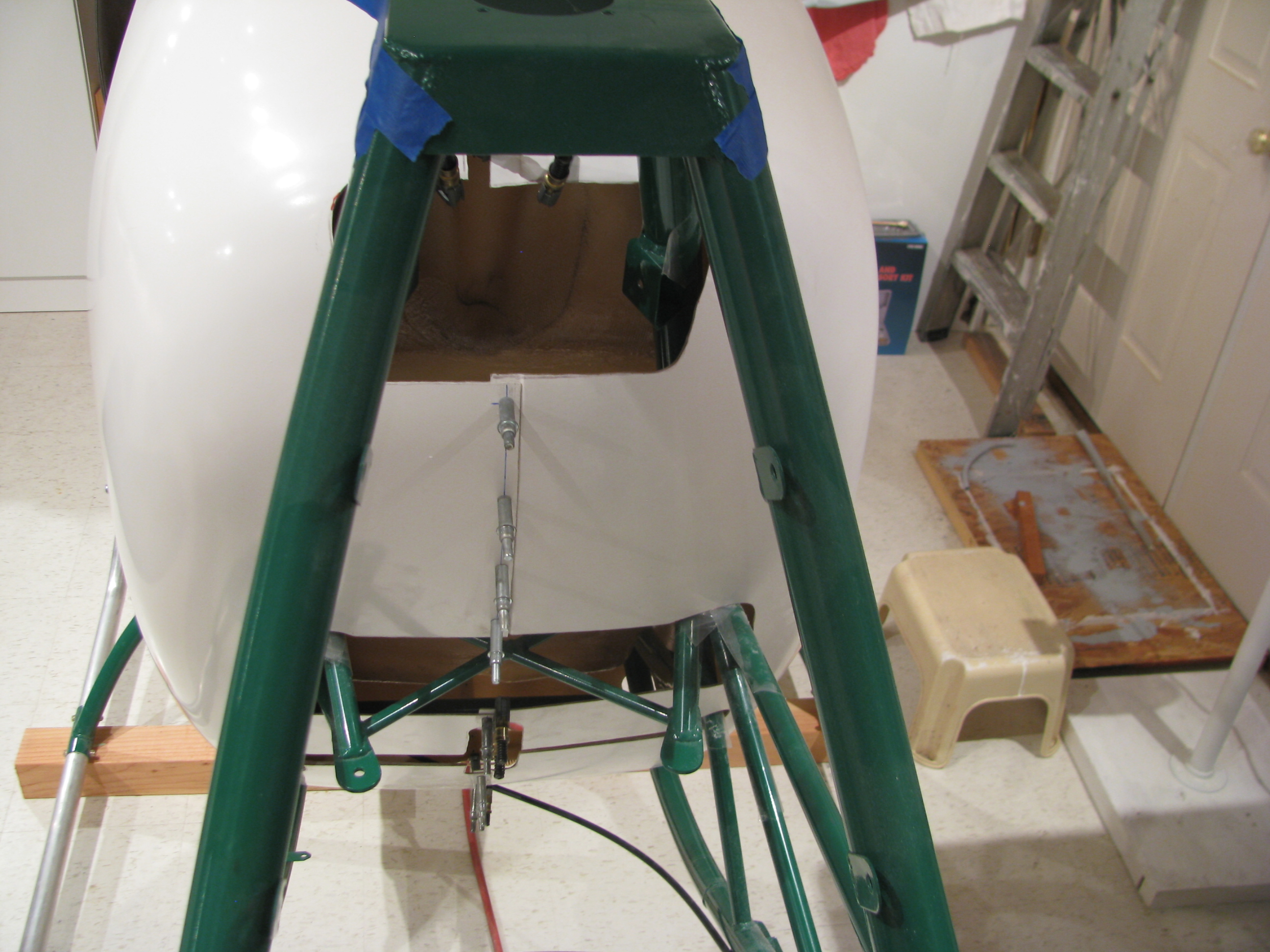
To drill the “blind” hole I first marked the arc at the correct distance, and also lined up a laser level with the hole from the outside. I started with a tiny bit and worked up to final, tweaking the position while checking from the inside.
It was only maybe 10 mils off by the time I got to final size. Not bad.
Confined Area Training
06/15/11 21:43 Filed in: All
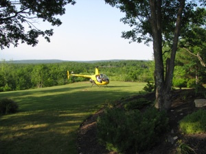
Confined area training. No better place to do it than my yard.

_________________________________________________________________________________
Getting closer. About 8 more hours of solos, a cross-country, then check-ride prep. Maybe another month. Better get cracking on the Helicycle.


_________________________________________________________________________________
Getting closer. About 8 more hours of solos, a cross-country, then check-ride prep. Maybe another month. Better get cracking on the Helicycle.
More BodyWork
05/23/11 22:01 Filed in: All
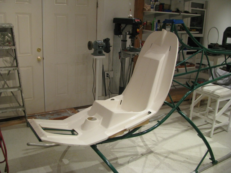
With the controls initially fit, it’s time to get back to mounting the seatpan and body shell. When I last left this task I had done all the fitting of the pan, and added some flox pads to fill the gaps between the pan and the metal tabs. They’re fit up pretty well and tomorrow I’ll drill the floorpan bolts.
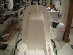
The pan pretty-well centered. The hump at the top is slightly offset to the right in this picture. This is because the mast will be slightly offset as well and the control rod presumably goes to the center of the mast.
Helicopter SOLO!!
05/22/11 21:40 Filed in: All
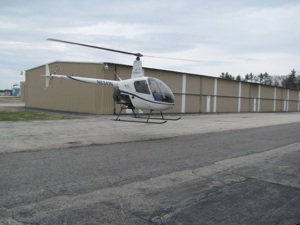
First Helicopter Solo!!! Well, we finally got a break in the crappy weather. After some hovering and a couple of laps in the pattern, Corey jumped out and I was on my own. Now, I remember my first airplane solo like it was yesterday. Heart racing and sweating buckets. It wasn’t that bad this time, but still pretty intense. It got the heartbeat to the aerobic stage I am sure. There is no greater sense of focus than flying a new type of aircraft by yourself for the first time.
Probably working against me was the fact that I watched the Robinson R22 safety seminar video on DVD the prior night. They go through the many ways that R22s fall out of the sky and how to get into and how to avoid unrecoverable situations. Pretty damn sobering and definitely forefront on my mind as I took the mighty R22 up on my own. All was fine, though and as with my airplane solo, the first couple patterns and landings were probably my smoothest to date.
Cool. Cool. Cool. 10 more hours of solo and 3 of checkride prep and we’ll be pretty darned close to the rating. More incentive to get cracking on that Helicycle. Let’s get back to building!!!
Training Restart
04/17/11 21:22 Filed in: All
It’s been about 2 years since my last stint of helicopter training. When I stopped I had about 10 hours logged, but my schedule at the time only allowed for maybe one lesson a week. With weather delays and the like, those ten hours took over three months to acquire. The first half of every lesson was spent relearning the last with the long delays between sessions.
I decided to restart the training, but this time I would take a week off of work and schedule two sessions a day to make as rapid advancement as possible. I started last Sunday (the 17th), and finished my week today. I logged about another 11 hours, doubling my total time in the span of a week. A couple of days were washed out due to New England springtime weather.
To my surprise, the basics came back quickly. I felt like an idiot during the first pre-flight as I had forgotten where everything is - a bad sign. But, the muscle memory was still fundamentally intact. The first 30 seconds were hairy, but I could still almost hover.
By the end of the week, I feel pretty OK about hovering, and there is some level of confidence that if my instructor Corey were to drop dead in the left seat, that I could continue the lesson and return the ship to C&R, insuring that his family got paid for the full lesson, without any bent metal on the ramp.
Autos are still not mastered. I can do one acceptably, but on the next one lose track of airspeed or RPM, or heading. It is not reflex yet, but still an intellectual process. Until the responses and control are semi-automatic, and the big three (RPM, airspeed, and position) are more in hand I would question my ability to complete one without balling up the machine. I am still having to THINK - RPM low, lower collective, OK, too high-raise it. Ooops, too much, back down. My responses are not fluid enough such that if I start chasing one parameter or the other, then we’re in for a roller-coaster ride.

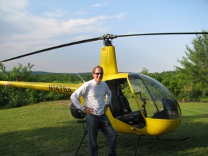
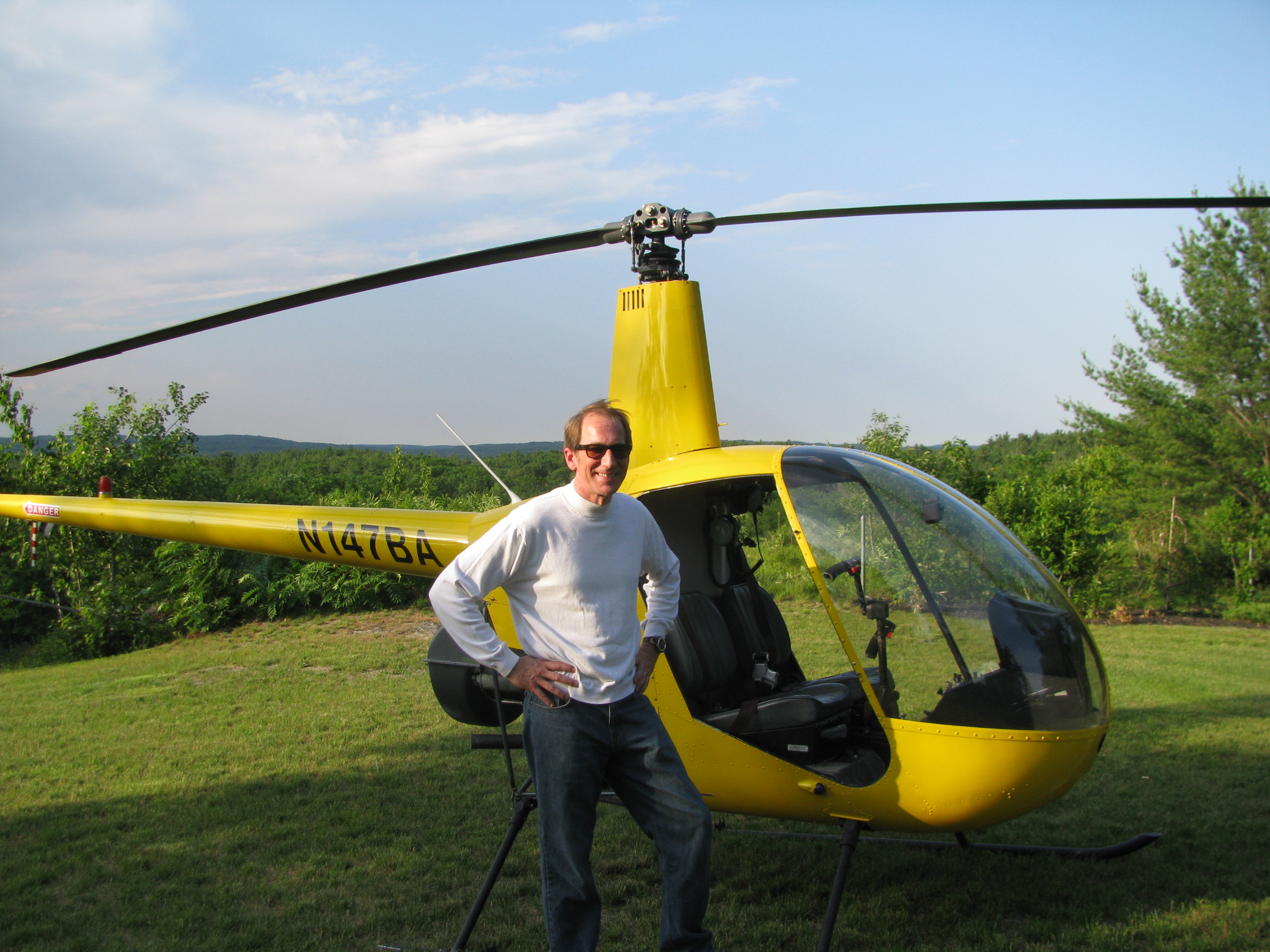
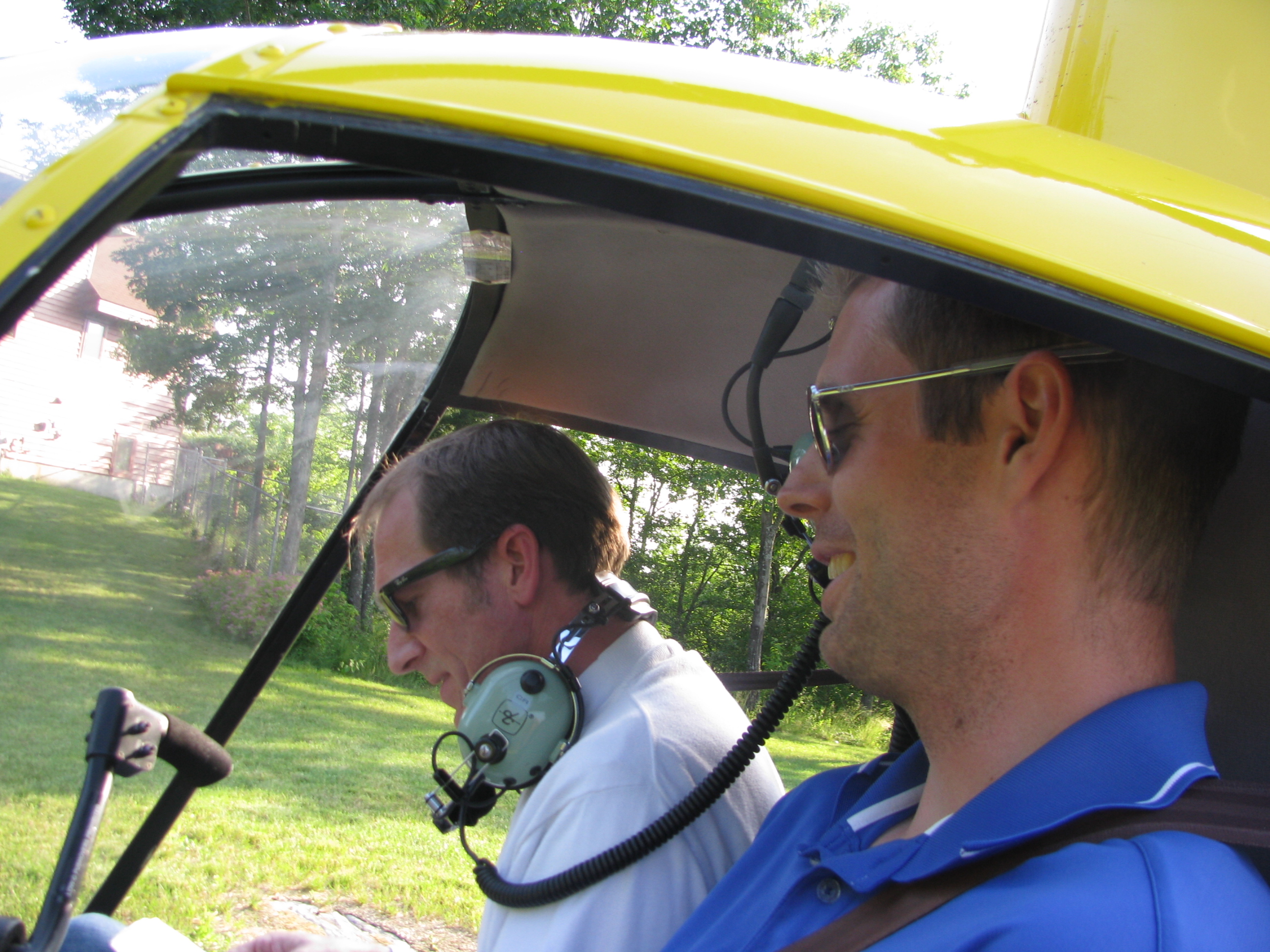
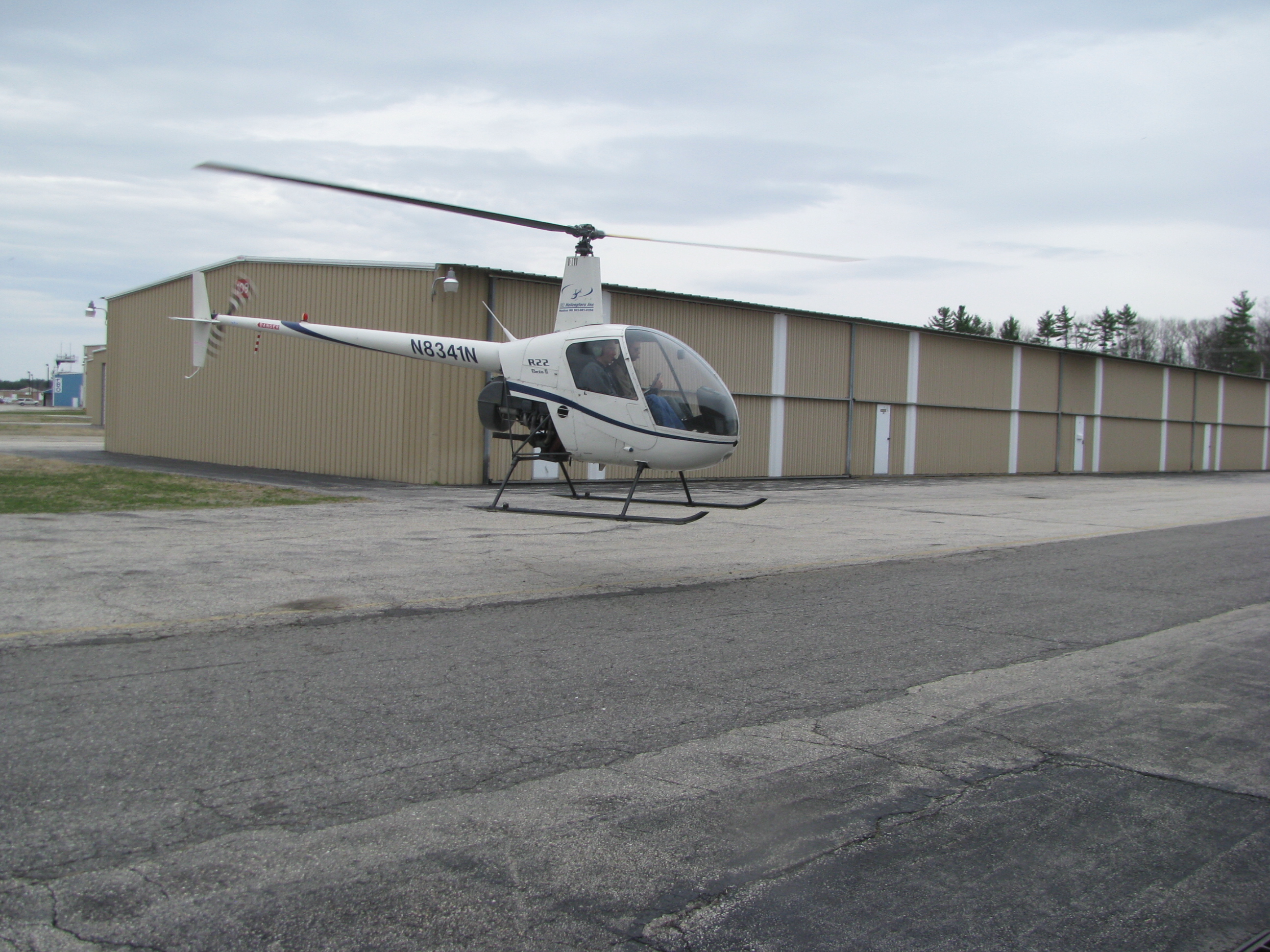
Lee came out to watch one day. She hid behind the trailer there when I started schwanging the mighty R22 all over the sky.
Still, comparing the start of the week to now is night and day. Whereas a wind gust during hover at the start would take 20 seconds to restabilize from, now it’s almost immediate. We’ve started to talk about the big solo. Maybe another 3 or 4 hours and we’ll be there. I want to feel much more confident about controlling the parameters in autos before we take that leap.
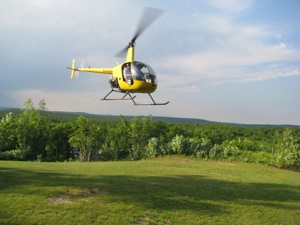
Here's a short video clip of a Platform Landing. Crappy Video quality from a distance. Just take it real slow
I decided to restart the training, but this time I would take a week off of work and schedule two sessions a day to make as rapid advancement as possible. I started last Sunday (the 17th), and finished my week today. I logged about another 11 hours, doubling my total time in the span of a week. A couple of days were washed out due to New England springtime weather.
To my surprise, the basics came back quickly. I felt like an idiot during the first pre-flight as I had forgotten where everything is - a bad sign. But, the muscle memory was still fundamentally intact. The first 30 seconds were hairy, but I could still almost hover.
By the end of the week, I feel pretty OK about hovering, and there is some level of confidence that if my instructor Corey were to drop dead in the left seat, that I could continue the lesson and return the ship to C&R, insuring that his family got paid for the full lesson, without any bent metal on the ramp.
Autos are still not mastered. I can do one acceptably, but on the next one lose track of airspeed or RPM, or heading. It is not reflex yet, but still an intellectual process. Until the responses and control are semi-automatic, and the big three (RPM, airspeed, and position) are more in hand I would question my ability to complete one without balling up the machine. I am still having to THINK - RPM low, lower collective, OK, too high-raise it. Ooops, too much, back down. My responses are not fluid enough such that if I start chasing one parameter or the other, then we’re in for a roller-coaster ride.

Lee came out to watch one day. She hid behind the trailer there when I started schwanging the mighty R22 all over the sky.
Still, comparing the start of the week to now is night and day. Whereas a wind gust during hover at the start would take 20 seconds to restabilize from, now it’s almost immediate. We’ve started to talk about the big solo. Maybe another 3 or 4 hours and we’ll be there. I want to feel much more confident about controlling the parameters in autos before we take that leap.
Here's a short video clip of a Platform Landing. Crappy Video quality from a distance. Just take it real slow
Control Rods
04/17/11 21:17 Filed in: All
Here’s a really bad Idea I don’t recommend - dipping the end plugs in primer. Ever anal about corrosion, I thought this would be a good idea. Even though the primer is very thin, it’s enough to make screwing in the rod-end bearings very difficult. Two turns in and one back out, almost like retapping the plugs. Once cleaned out they’re fine, but I am sure it was hard on the threads.
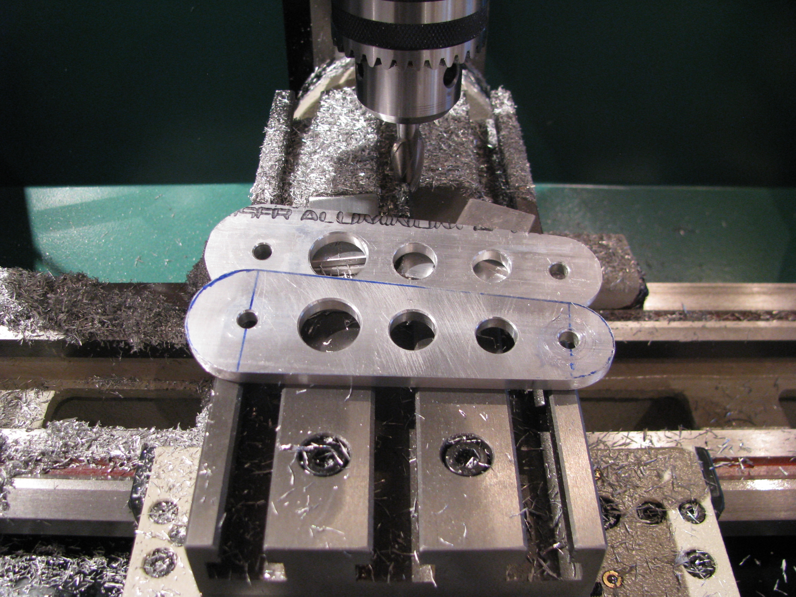
Another commercial for the Grizzly mill/drill. Bolt together the walking beams, bolt to the table at 3.5 degrees and mill away. Afterwards 20 seconds on the belt sander and done. Careful as the edges on milled parts are razor sharp.
All you machine shop nazis can rail on me for not using the proper collet on the mill, but changing is a pain and I took very small cuts. Of course I would switch over for more extensive jobs.
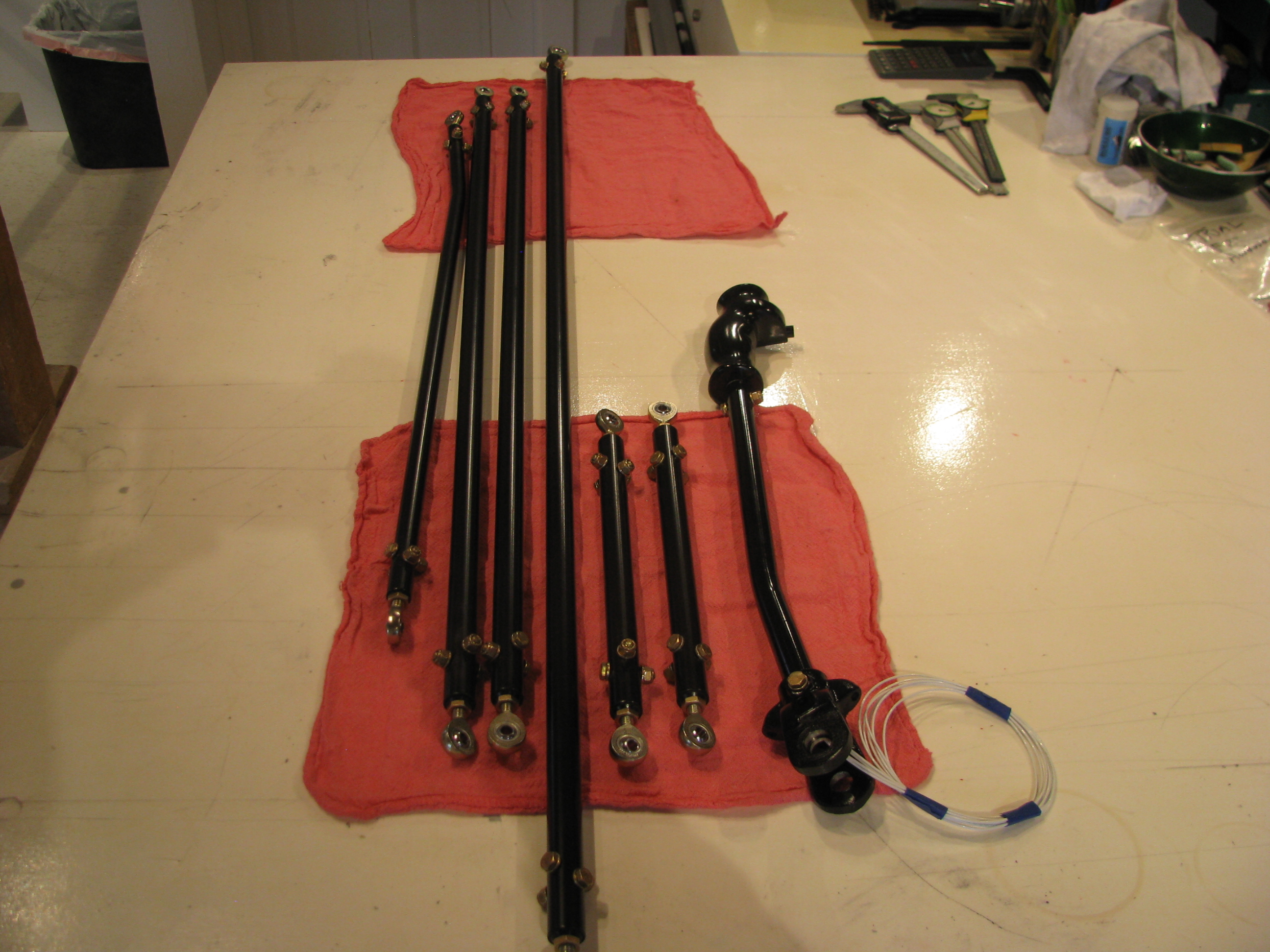
Parts starting to look finished - because they ARE finished. I know these will probably get dinged up during the continuous fitting/refitting, but the epoxy paint should be easy to touch up just before final assembly.
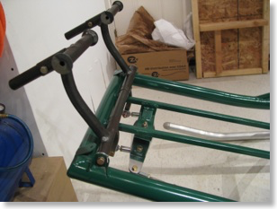
Cyclic assembly in ship with control rods preliminarily placed.
Front end of cyclic stick mounting.
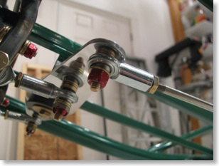
Top view of mixer and rods.
Bottom view of mixer. Lots more washers than really needed so I don’t bite into nylon on any of the lock nuts.
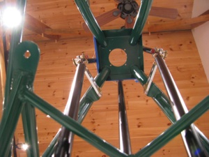
Looking up at walking beams. Obviously they are not set to the proper angle yet.
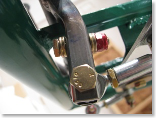
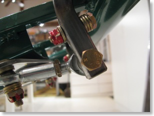
This is a clearance issue with the stick full forward - actually it limits the stick from going full forward. You can see the fore-aft rod end touching the mixer bracket. I could grind a little off the mixer, but I am going to wait until things are closer to being in rig to worry about clearances. The main thing is that it all fits and there is little or no slop at all in the controls and they all move cleanly. Very cool to see this come together. There is almost no friction in the system and BJ seems to indicate that a little friction is a good thing, so I will go back and reinvestigate.
Of course now it all comes back apart.
With the preliminary placement I can see the extent of the travel on the slider. Now I can go back and clean up and paint the cyclic control tube.
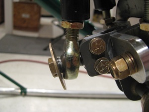
I just have one support call to make to Eagle, which will be my first. The mixer U-shaped aluminum wings are held together with an AN4 bolt (which looks to be a change from the machined bolt in the videos). Two washers are supplied - presumably one for under the head of the bolt and one for under the castellated nut. Well, with a washer under the nut there is not enough clearance for the rod end to move. Without the washer the nut rides right on the aluminum of the “wing”. That doesn’t seem right. Hmmm...
Cyclic Update
04/11/11 21:15 Filed in: All
4/11/2011 Update: I received the “Close Tolerance” bolts from Aircraft Spruce and they are cool. The diameter is only a few mils larger than the AN equivalent. In my case I could feel a little side-side where the cyclic stick to casting bolt felt a touch loose. With the Close Tolerance bolt there is no play and I have to tap the bolt in with a screwdriver base to get it in. Nice. No re-drilling or bolt upsizing required. I am keeping an assortment of these sizes on hand for just such occurrences.
No major building activity this week due to work/travel/taxes.
No major building activity this week due to work/travel/taxes.
Cyclic Controls
03/26/11 18:27 Filed in: All
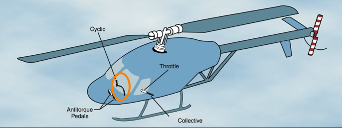
The Cyclic Controls direct fore/aft and lateral changes in force applied to the motion of the helicopter. This is probably the most complex part of the Helicycle design and as I have started to build it I am gaining appreciation for the elegant simplicity of the design employed. It’s hard to envision how it works together from pictures until you hold the parts in your hand and see the complex mixing of inputs performed. The cyclic control inputs and collective control inputs have to get mixed together before being applied to the direct rotor head controls.
Precise and careful manufacture of these subsystems will be undertaken to result in a smooth, slop-free response to operator input.
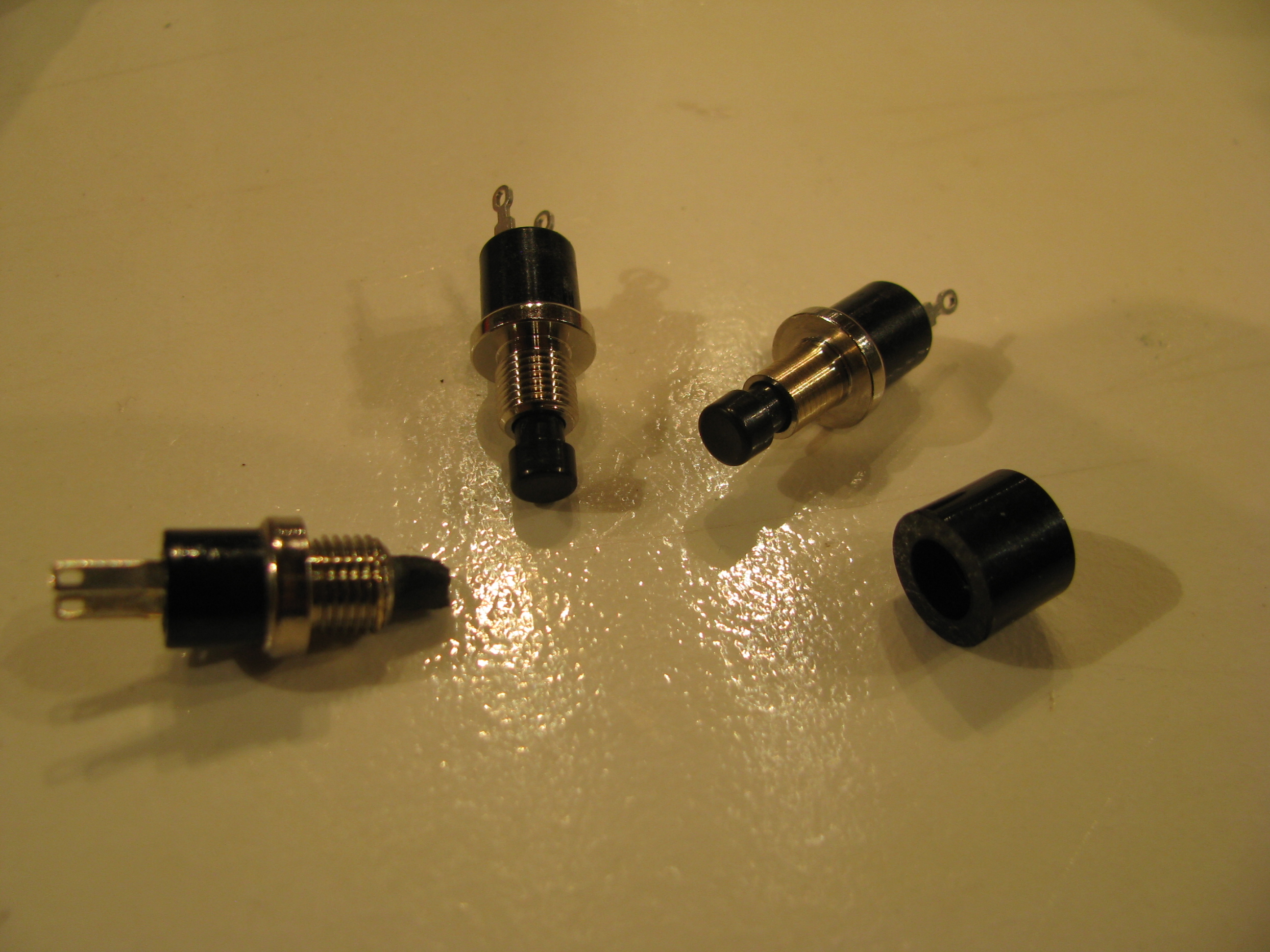
Of course having said that, the first thing I did was to break off the head of the Mic switch while trial fitting it to the handgrip. I got a couple of closest match replacements from Digikey (there are no visible vendor markings on the switch from the kit). The button head did not slide over the threads of the new switches, so I just lathed off the threads. The button head will get epoxied to the end of the new button switch.
Several hours shot finding replacements and reworking something that should have been quick.
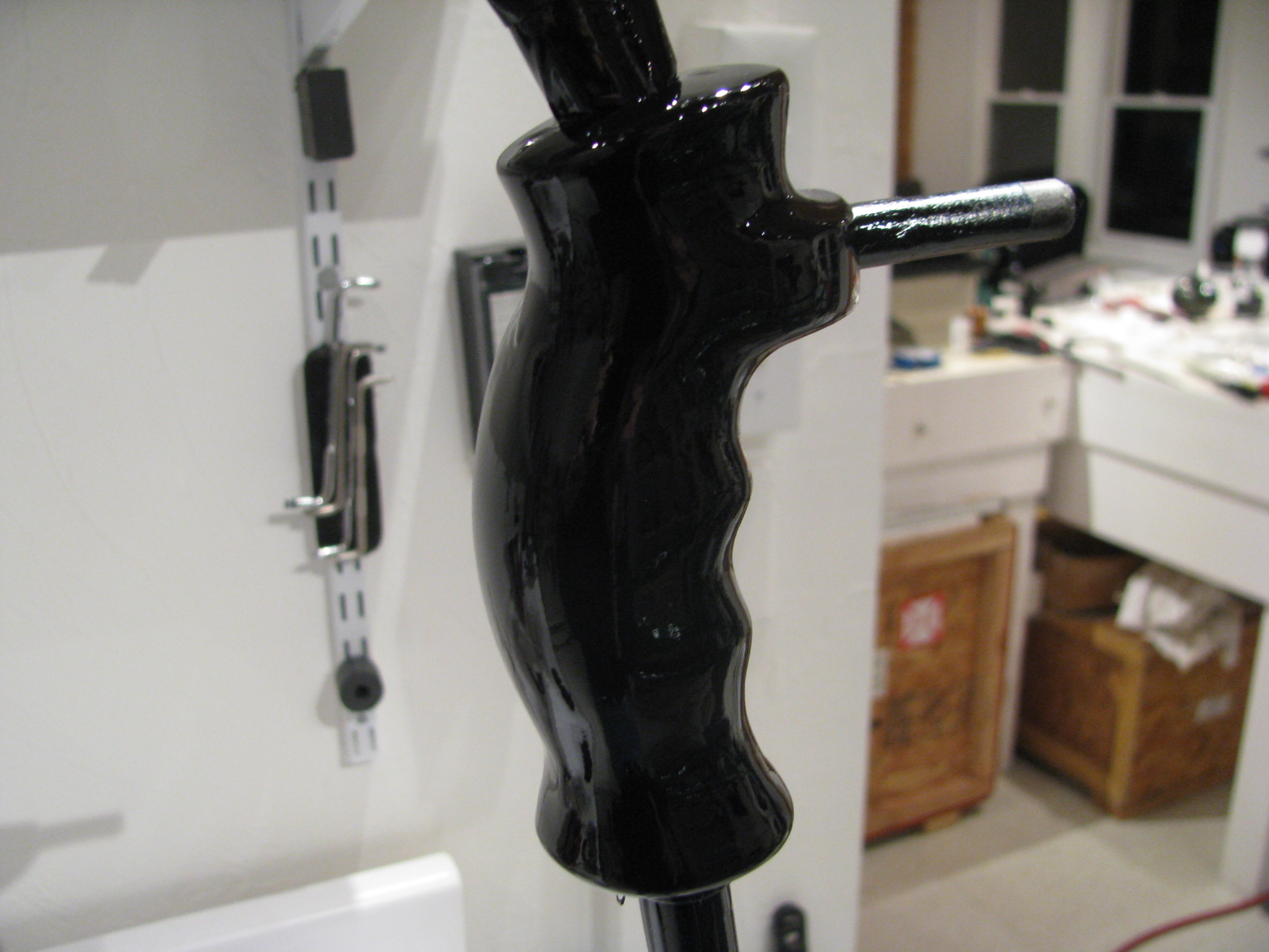
The grip provided seems fine for me. I know a lot of folks have replaced this with something more advanced, but using the top button for flip/flop on the radio, and the trigger for the Mic should be adequate for me.
Gotta remember to keep it simple or I will be building forever.
Some sanding and smoothing is required as the grip appears to be rough cast of an epoxy resin, then 6 coats of the VHT epoxy paint hopefully will prove durable.

Cyclic stick drilled to the casting. I must say that I am amazed just how many custom castings are included in this kit.
Another mistake. The bolt fit is kind of sloppy here, like the hole is maybe 1/64 too big. I don’t know whether I grabbed the wrong bit, or didn’t have the casting clamped well enough while drilling. I will first try a “close fit” aircraft bolt and then decide whether to bump up to an AN4 bolt.
Too bad, though. The hole is nice and square and centered. It’s always something.
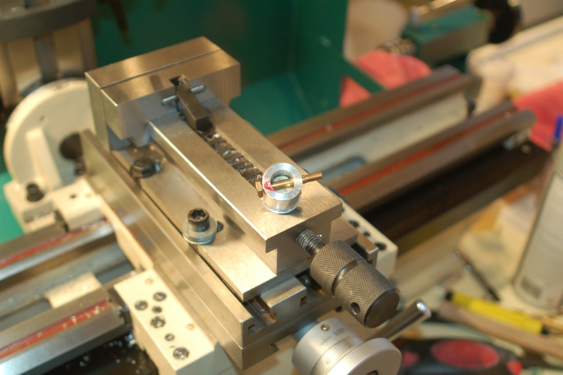
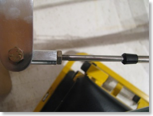
The steel plug for the front cyclic control tube was about 5-10 mils too large. Chucked it in the lathe and sanded it down a touch until it was very just very snug.
Had to sand the interior of the tube where the travel limit bracket was welded on. There were a few bumps where the tube deformed slightly while welding. Now the fit is snug, requiring just a light tap with a screwdriver handle to fit. Then I drilled the keeper bolt. Again, the mill/drill allows for a nice clean, square hole.
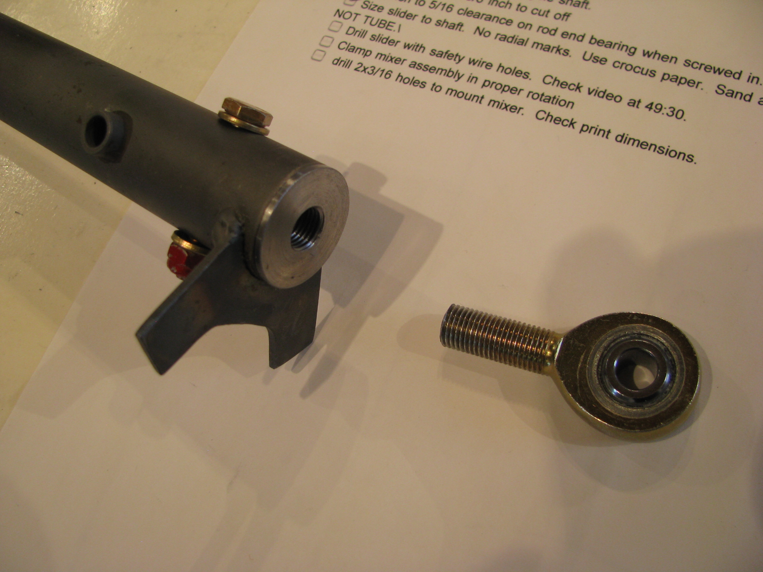
Cut 3/8 off the rod end and cleaned up the threads. The inner bush on the 5/16 rod end is very tight, even with additional grease. I may order some others if I can not get it to loosen up.
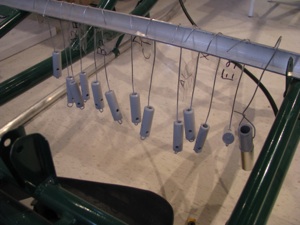
I agonized over how to make the holes for the safety wire/spring attach holes on the collective slider. After conjuring up many Rube Goldberg mill clamps, I ended up just free-handing it with a hand drill.
It’s a whacky angle since you definitely want to miss the interior features of the slider, but want the holes to pass through plenty of “meat” on the slider to stay strong. In both cases I was within 1/16 of my planned exit hole while drilling. Not bad. Start very small and work up very gradually, “steering” the smallest bit on the first cut.
Trial fit-up of the mixer assembly. Neat little assembly. Sanding and grease really do affect the feel, so follow the tapes closely.
My kit was different than the tape and the plans in that there is an AN4 bolt between the U-shaped wings instead of the machined allen bolt that BJ refers to. It was in the correct bag and fits properly, so I am assuming this has been updated since then.
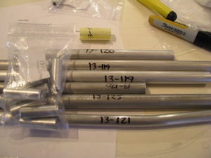
As a diversion, before drilling the mixer to the cyclic tube, I decided to knock off the control rod fabrication. I don’t know whether the kit came this way, or I did it to myself when we moved, but the rods were all taped together with cheap packing tape that left glue all over the rods.
It took about an hour with Goof-Off to clean them all up. That stuff was persistent. Goof-Off got its name because it will make you goofy if you breathe too much of it.
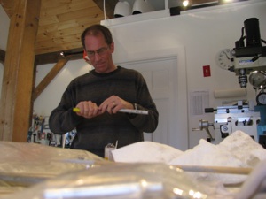
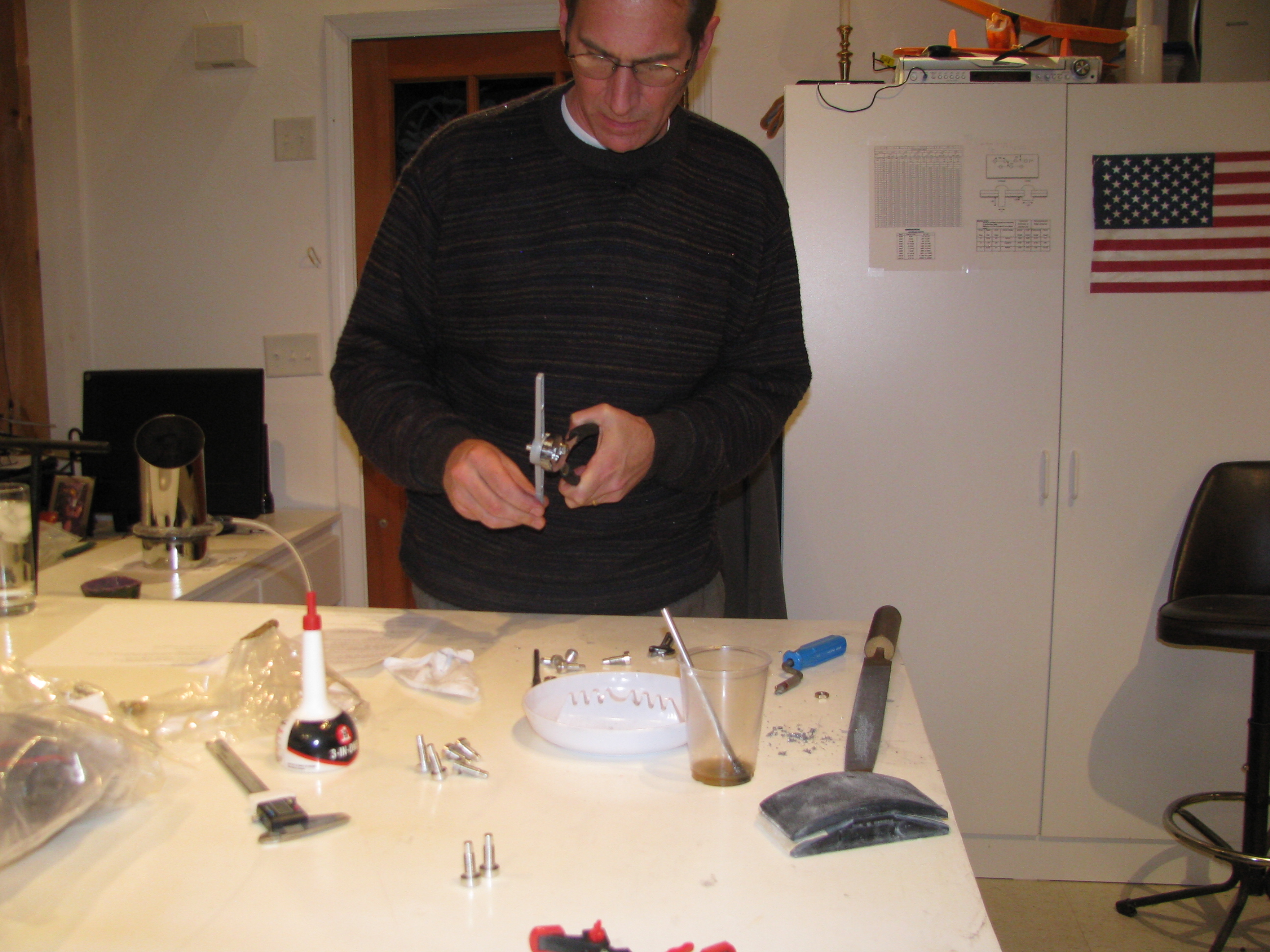
Obligatory, FAA-mandated picture of me deburring control rods. I engineered the shop lighting to highlight encroaching baldness. Works pretty well, eh?
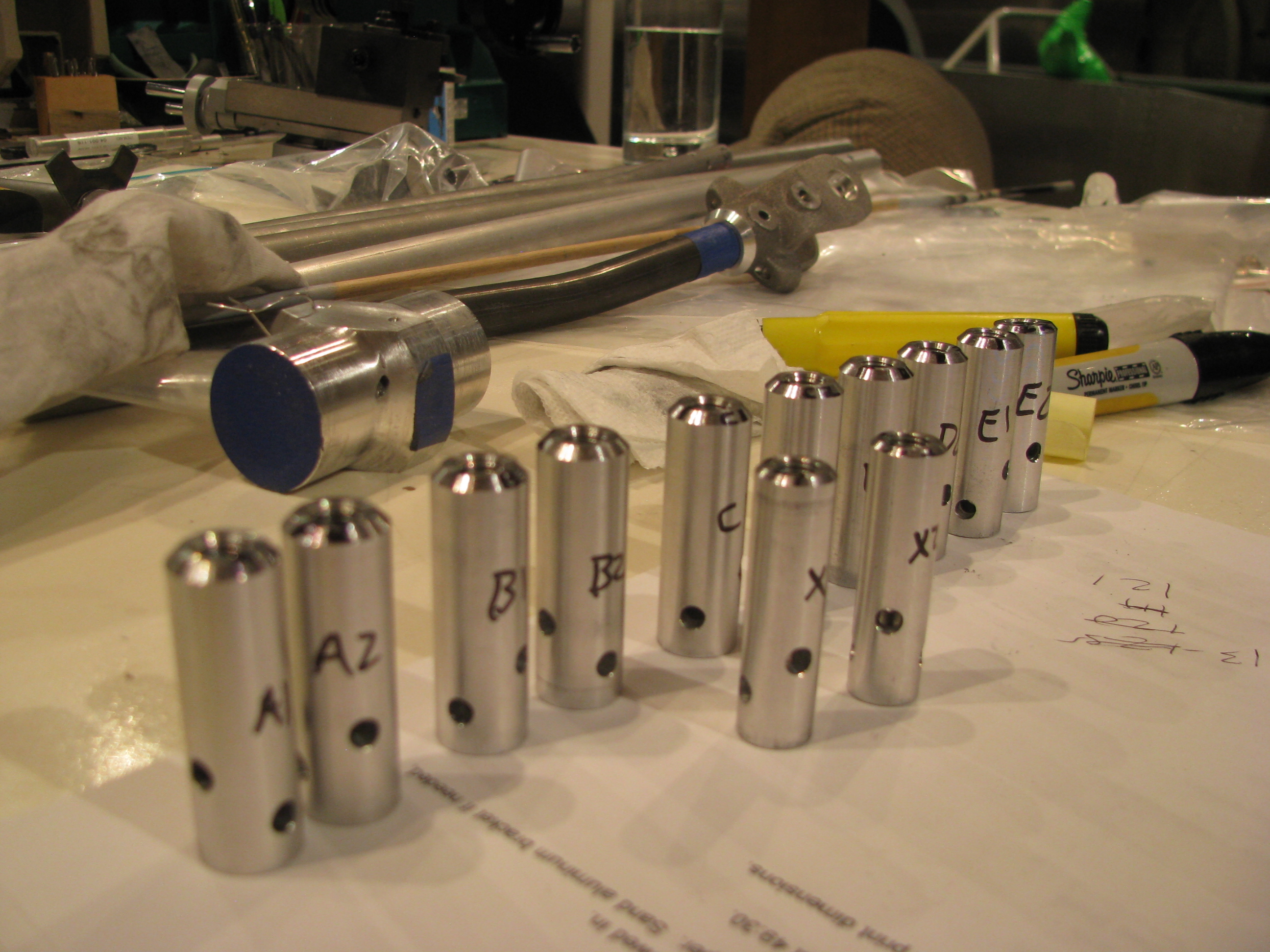
This was another one of those jobs that looks really quick, but took all afternoon and evening to clean up the rods, fit and drill the control rod end plugs into the rods.
Perhaps I was being overly anal about perfect 90 degree angles between the bolts, but that’s always been very visible to me and an indicator about the quality that may exist elsewhere on the ship. I did notice that even BJ’s bolts are not all perpendicular to each other on the construction videos.
I think it was Tim Drnec’s site showing how he welded the plugs and ground the rods so no bolts were visible at all. That’s really cool and I am sure it looks great, but a little over-the-top. I’ll live with the bolts. It’s my mantra now: “Follow the plans and finish the project. Modify later.”
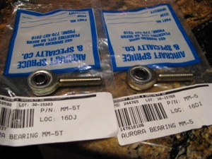
Not satisfied with the freedom of the end bearings I purchased another set from Aircraft Spruce. One is the teflon race insert (type T) and the other is the plain copper insert. The plastic insert rod end is as stiff as the the one supplied by the kit. The copper insert is as smooth as butter.
I am going to replace the ones in the kit (teflon insert) with plain copper inserts for smoothness of motion. Of course the ones I got were wrong. They are MM-5 and MM-5T. BJ uses XM-5 rod ends, which are heavier duty and larger. Crazy non-intuitive numbering system. The XM versions are not available at A.S. I had to order them from Wicks. The only possible downsides might be that the metal on metal requires periodic lubrication and might possibly cause some RF interference, but seeing as he used non-teflon rod-ends for all the smaller ones this can’t be a problem.
Collective Controls
03/13/11 18:02 Filed in: All
 Having wrapped up most of the fin construction I jumped into the collective controls. This is a pretty straight up section with light fitting and machining. It gave me a chance to use the mill/drill/lathe. That thing is cool. Way more precise than anything I could achieve with a drill press alone.
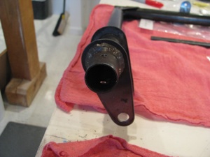
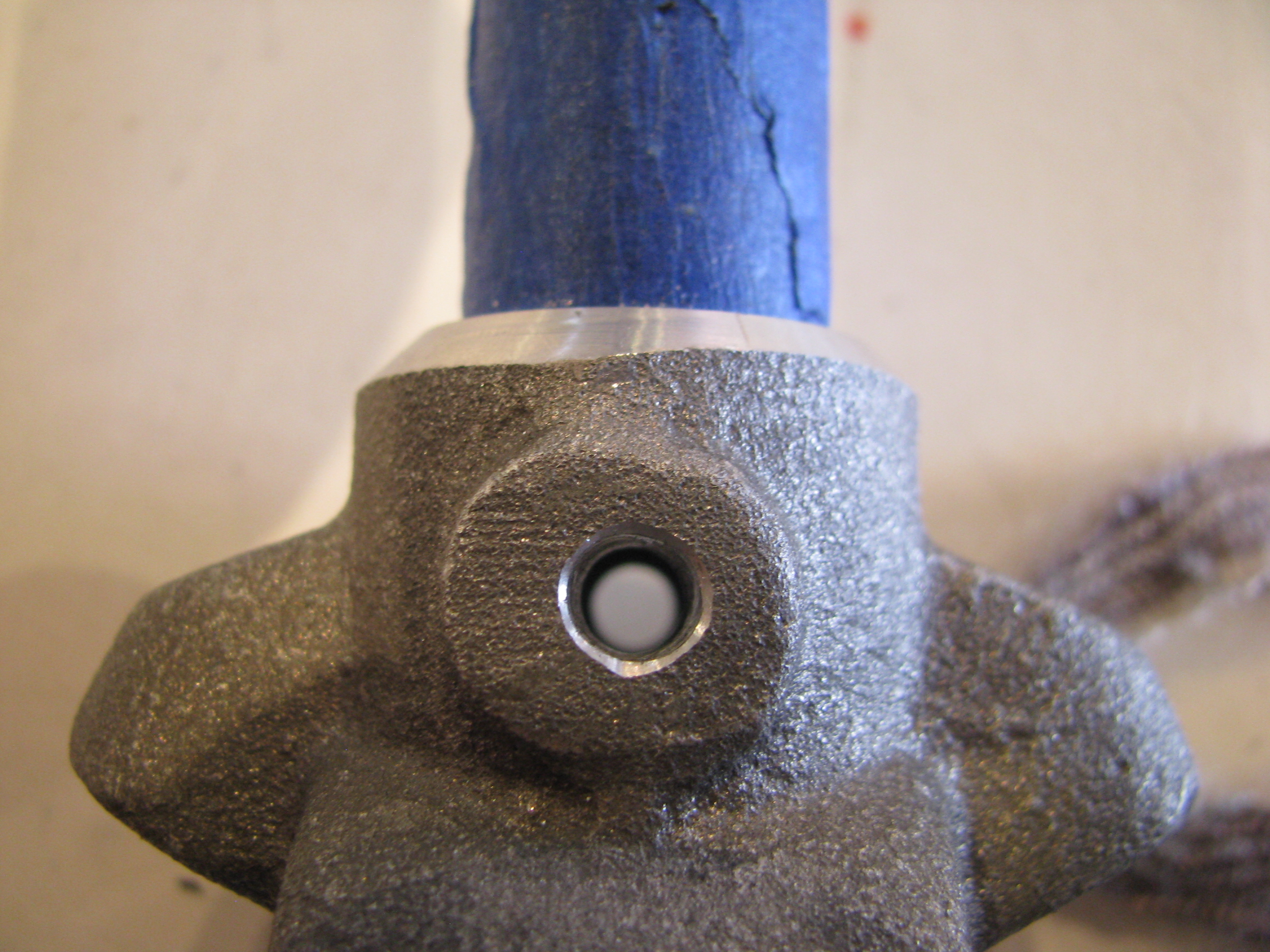
Start by drilling the end plug into the pivot end of the collective weldment. In the video BJ tells you to hammer a bolt into the aluminum plug. That didn’t quite sit right with me. So I lathed the bolt head down so it fit very snugly in the cap. The problem is that the “hammering” action is what would have held the bolt in the cap when the nut is tightened. Since the bolt is the pivot for the collective shaft it is not snugged down super tight. If it were to ever loosen up in there; a) There would be slop in the control, and b) it would be impossible to unscrew the nut off the end of the bolt.
So I measured and drilled right at the point of the bolt head, tapped the plug for little 8-32x3/16 set screws that will sit inside the plug, and drilled a little into the bolt head. Same treatment on both sides. I’ll install the bolt, and loctite the set screws. That bolt isn’t moving.
Of course doing this with just a drill press would be a pain, but the repeatability of the mill/drill allow the operation to be repeated easily from a fixed reference point.

The completed plug assembly.
The collective is held in two places. The first is the pivot plug/bolt previously described, and the second is this aluminum construction. Two pieces of aluminum are supplied cut from bar stock. The corners must be radiused, which is no simple trick since they’re about an inch thick.
First the angle grinder, then the big belt sander and vixen file, then the little belt sander and sandpaper. This operation takes a lot longer than you ever would imagine.
The result is worth it, though. There is something very satisfying about shaping aluminum from rough into beautiful. If I elect to paint this the finish is ready to prime. If not, I’ll give it a bit of a polish and clear coat, but since it’s buried pretty deeply in the structure I’ll probably not invest the time.
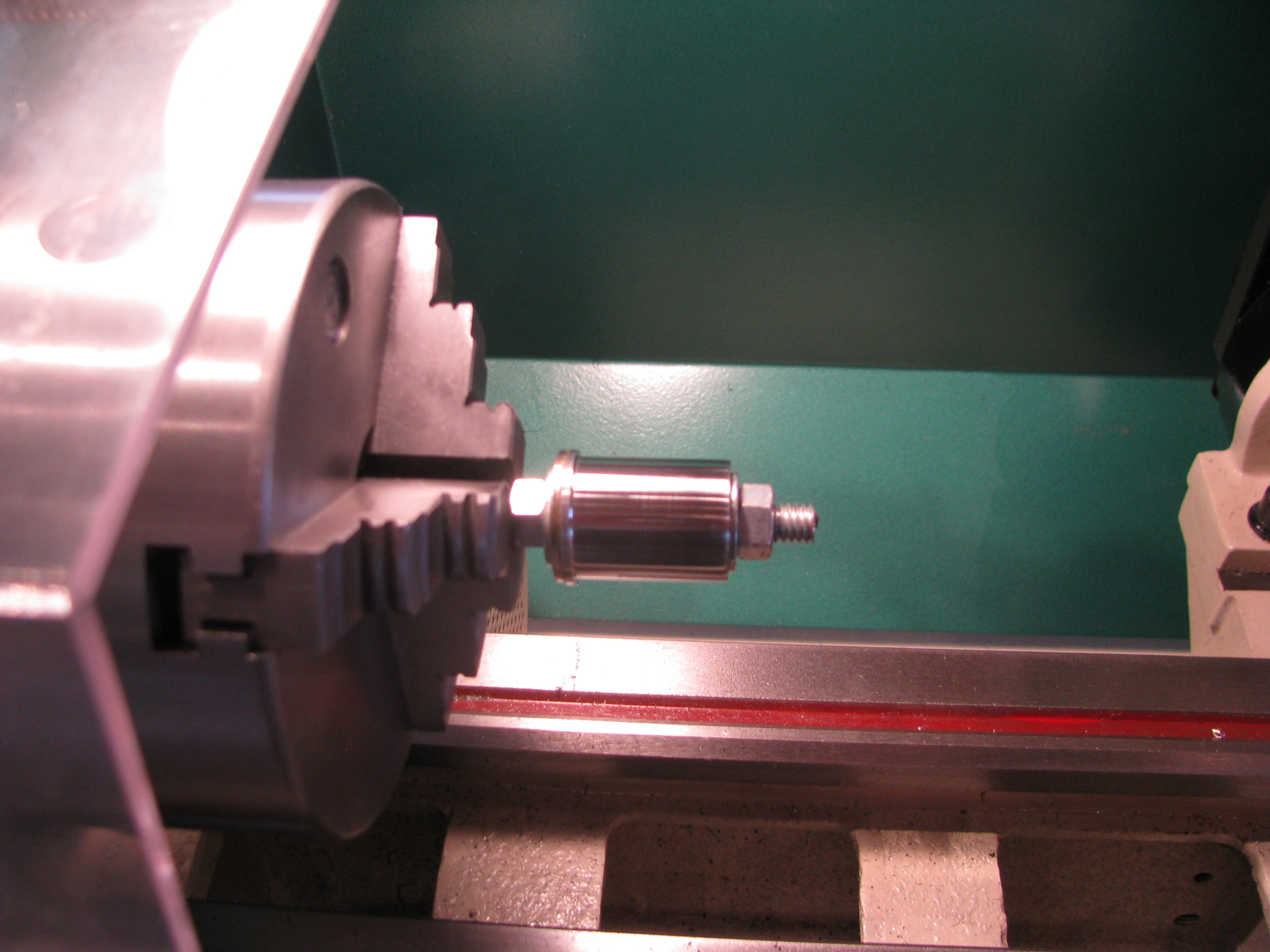
I cannot find the supplied throttle grip in the parts bags, so I suspect it did not find it ‘s way to me when I purchased the kit. I ordered an aftermarket Harley Davidson throttle grip. The 1-1/8” OD throttle grip shaft matches the throttle handgrip on certain model Harleys (49 to 73, I believe). Plenty to choose from out there of all sizes and prices.
BJ tells you to 5-minute epoxy a length of 5/16 bolt into the end of the throttle twist shaft for the set bolt to “bite” into. Since I have to justify the expense of all this equipment, I milled a little flat onto the bolt section, just because it felt like the right thing to do. Instead of 5-minute, I JB Welded the slug into the end of the shaft after the hole had been drilled and positioned.
The slug, the shaft, and the collar that links the throttle twist shaft to the potentiometer shaft.
Potentiometer holder insert and bolted into place. This is actually a fairly complex machined part for such a simple function.
About 15 minutes of sanding and polishing were all it took to shine up the collective and throttle friction knobs. Mother’s Mag polish hasn’t failed me yet. Flitz seems to be recommended highly, but since I have two cans Mother’s, I am going to use it up first. I did mask off the knurled sections since the black polishing residue would probably be a pain to get out of there.
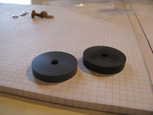
My parts bags only had a single plastic friction washer for the Collective Friction Assembly. The prints show one on either side of the collective friction slider bar, so I made one up from some plastic stock I had on hand. I think it’s phenolic. It feels similar in texture to the provided part. I am learning the lathe. Diameter is easy. Facing is easy. Parting and finishing the second side is not so easy on a part this thin. Parted with a hacksaw blade (it’s plastic), and was just able to get it in the chuck enough to face the second side. The tool was very close to the jaws of the chuck while facing.
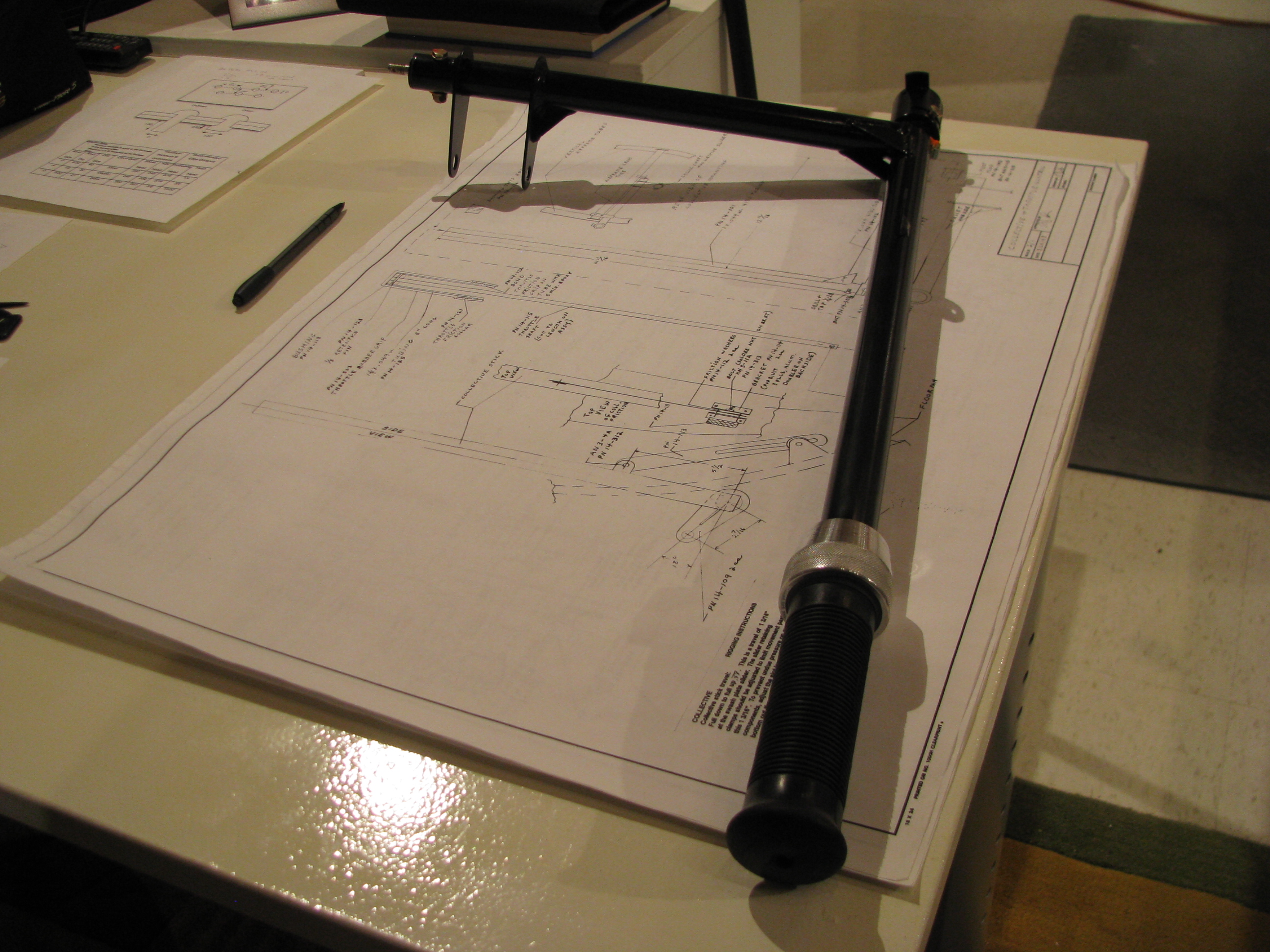
The completed throttle/collective assembly ready for installation into the ship. After experimenting with a few different grips, I ended up with one I bought just like the one BJ provides in the kit. It’s a Harley OEM-type throttle grip. None of the others I bought seemed appropriate for a Helicopter.
A light sandblast with 220 grit media to remove surface corrosion from the tube assembly and VHT single-part epoxy paint. Seems like good stuff as long as you let it cure for the many days specified before knocking it around.
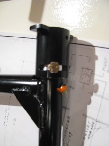
The potentiometer holder final bolted in place (obviously not the throttle pot linkage, though). Anywhere I “final” assemble a bolt and torque it to spec I use a little torque seal, not just as a movement indicator, but as a reminder to myself.
I can’t count the number of times I have let something sit for a week and then can’t remember if I completed this little operation or that. Any/all reminders help my advancing memory.
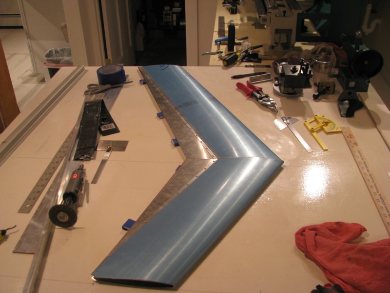
Finished Vertical Fin
03/06/11 17:55 Filed in: All
Finished construction on vertical fin. Primed the inside of the spar and the fin sections by just cleaning and pouring in the primer and sloshing it around. Should be good enough since the fins are already alclad. The outsides are primed too. I am a prime-as-you-go kind of guy having had bad experiences with corrosion in the past.
Here’s little trick I read about elsewhere and modified a bit. To locate the exact, precise centerline of the steel spar under the fin I got these little powerful half inch round neodymium magnets. They naturally seek the spar centerline. Just prior to the rivet location, make a little “puddle” of Sharpie ink (or machinist's ink if you have it) and “push” the magnet through the puddle across the rivet line using a piece of aluminum.
Invariably the spar is not precisely on the measured and marked centerline. Using this trick the magnet pushes a line of ink and gives you the exact drill point. This one is toward the end of the fin and is off the measured line by about 1/16th of an inch.

Had I just drilled on the drawn spar line the rivet would have been slightly off center of the spar and a dimple would have resulted when the rivet drew things together and canted .
Here are the pieces coming together for the final time before riveting. You can see where I drilled out the lower rivets of the lower section so the curved tube would fit through without damaging the thin skin.
Here’s little trick I read about elsewhere and modified a bit. To locate the exact, precise centerline of the steel spar under the fin I got these little powerful half inch round neodymium magnets. They naturally seek the spar centerline. Just prior to the rivet location, make a little “puddle” of Sharpie ink (or machinist's ink if you have it) and “push” the magnet through the puddle across the rivet line using a piece of aluminum.
Invariably the spar is not precisely on the measured and marked centerline. Using this trick the magnet pushes a line of ink and gives you the exact drill point. This one is toward the end of the fin and is off the measured line by about 1/16th of an inch.
Had I just drilled on the drawn spar line the rivet would have been slightly off center of the spar and a dimple would have resulted when the rivet drew things together and canted .
Here are the pieces coming together for the final time before riveting. You can see where I drilled out the lower rivets of the lower section so the curved tube would fit through without damaging the thin skin.

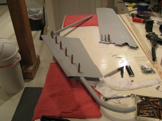
Fin Fabrication Start
02/04/11 17:45 Filed in: All
The fins use a prefabricated airfoil section that has to be cut per the plan, then fit to the steel tube spar. Cutting to shape was no problem, but I committed my first helicopter part butchery on the lower section. The tube spar has a curved lower section. In jamming it through the airfoil section I made a faint crease in the very thin aluminum skin. What I should have done is drill out the lower rivets to allow for easier fitting and riveted it back together on final assembly at the end. Oh well. Apparently I am not the first to have done this.
A replacement fin has been ordered, and surprisingly has arrived within a week. The box it came in also contained a turbine. Hooray!!! I have been pestering Eagle for almost the last year asking about my turbine. The answer was also “two more weeks”. Well pester-no-more. I have no immediate use for it, but I feel so much better having all the major helicopter pieces in my possession. No matter what happens to Eagle - not that I think anything will - I will be able to complete my machine.
Pedal Fitting
01/07/11 17:00 Filed in: All
Back to Work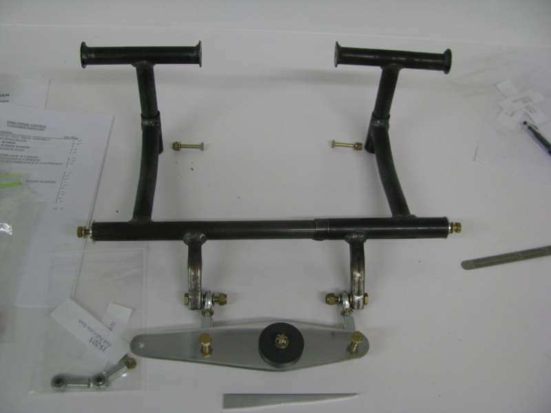
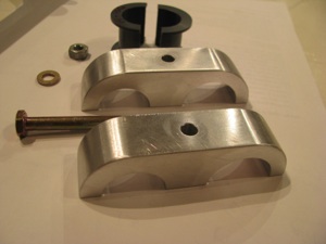
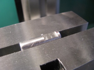
The directional pedals are a fairly straightforward sub-assembly, so it was an easy thing to work on to get back in the swing of helicopter work. I cut the walking beam and tried my hand at polishing. Aluminum takes on a wonderful shine with a bit of work.
These photos are as much for my own benefit as for any reader that may (or probably won’t) read this. Once fitted things get disassembled and will need to get back together properly.
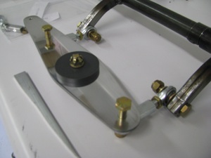
A little technique carried over from the RV building is to take a handful of nuts and drill out the nylon lock plastic. These can be used for preliminary assembly and will have the exact size of the final item. I mark all those trial nuts with red nail polish to make sure they will not find their way into the final assemblies.
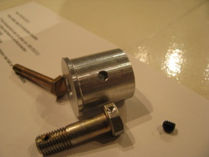
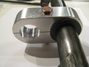
I have read a number of builder logs that have replaced the aluminum pedal bearing plugs with a more suitable material since aluminum on steel is not the best long-term idea. I may do so eventually as well. One thing I learned in my years of abortive aircraft building is that I should build per the plans and modify later - otherwise it’s likely I will never ever finish in the first place.
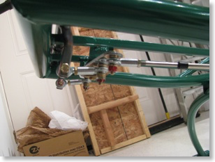
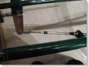
It took a lot of fiddling, but I was finally able to achieve the pedal and cable travel specs called in the prints. Hopefully this will be duplicatable on final assembly.
The directional pedals are a fairly straightforward sub-assembly, so it was an easy thing to work on to get back in the swing of helicopter work. I cut the walking beam and tried my hand at polishing. Aluminum takes on a wonderful shine with a bit of work.
These photos are as much for my own benefit as for any reader that may (or probably won’t) read this. Once fitted things get disassembled and will need to get back together properly.
A little technique carried over from the RV building is to take a handful of nuts and drill out the nylon lock plastic. These can be used for preliminary assembly and will have the exact size of the final item. I mark all those trial nuts with red nail polish to make sure they will not find their way into the final assemblies.
I have read a number of builder logs that have replaced the aluminum pedal bearing plugs with a more suitable material since aluminum on steel is not the best long-term idea. I may do so eventually as well. One thing I learned in my years of abortive aircraft building is that I should build per the plans and modify later - otherwise it’s likely I will never ever finish in the first place.
It took a lot of fiddling, but I was finally able to achieve the pedal and cable travel specs called in the prints. Hopefully this will be duplicatable on final assembly.