
Detail Fuel System Work
11/20/11 23:30 Filed in: All
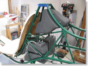
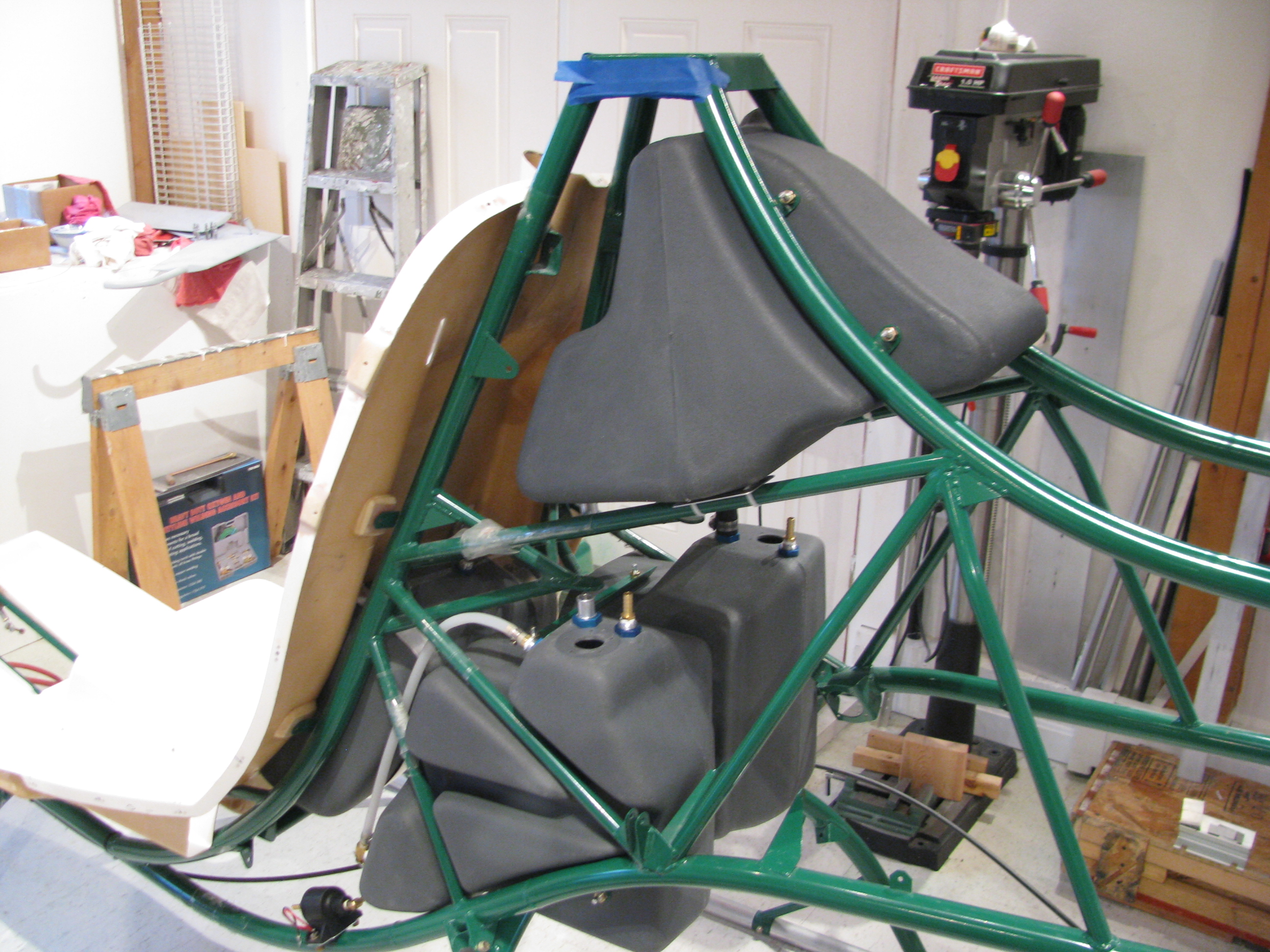
More fuel system detailed work. I fitted the tanks to the frame and drilled the appropriate mounting holes. This is not too demanding of a task, just a lot of little fitting and futzing. Of course the shape of the frame and the shape of the tanks is not super precise in the fashion in which they fit together, but it’s pretty close. I think the fuel system is a +/- 1/8” kind of precision as opposed to a 5mil kind of operation. EXCEPT the fittings. To be leak free these should be snug and tight fitting.
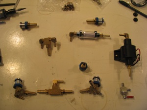
There are a lot of bits and pieces in many, many bags. I will admit that I did not inventory the fuel system when I took delivery of the kit, but everything seems to be there. So far the only thing I have been missing in the entire kit thus far has been one thin washer back in the mixer assembly.
The top tank is fitted out and drilled. I corked and checked for leaks with water. I plan on pre-assembling the entire fuel system in the ship and leak testing it in its entirety, then remove it all and then setting it aside until final assembly.
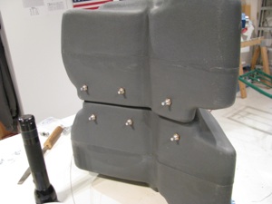
Fitting the lower tanks and drilling the spreader plates. I actually fished the little fittings through during the drilling op as they held the tanks more securely than just bolts pushed into position.
Plus, you’re doing this drilling upside down on your back, which is a little awkward.
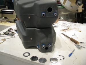
Fittings all installed in the lower tanks and the holes enlarged. I went ahead and drilled both cover plates. I do not plan on using the Westberg gauge and sender as I plan on using a fuel totalizer. In all the planes I have flown or owned I never use the fuel gauge. Time and total fuel actually used as reported by a totalizer has been far more accurate and reliable.
My Glasair gauges are useless as there is only a small band of gauge movement where they are actually in motion somewhere in the middle of the overall capacity. The totalizer is far more accurate.
Of course the thing you lose is the remote possibility of a catastrophic leak being detected in time to set it down before all fuel has leaked out. I’m willing to accept that.
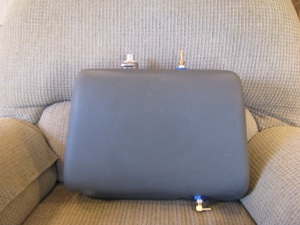
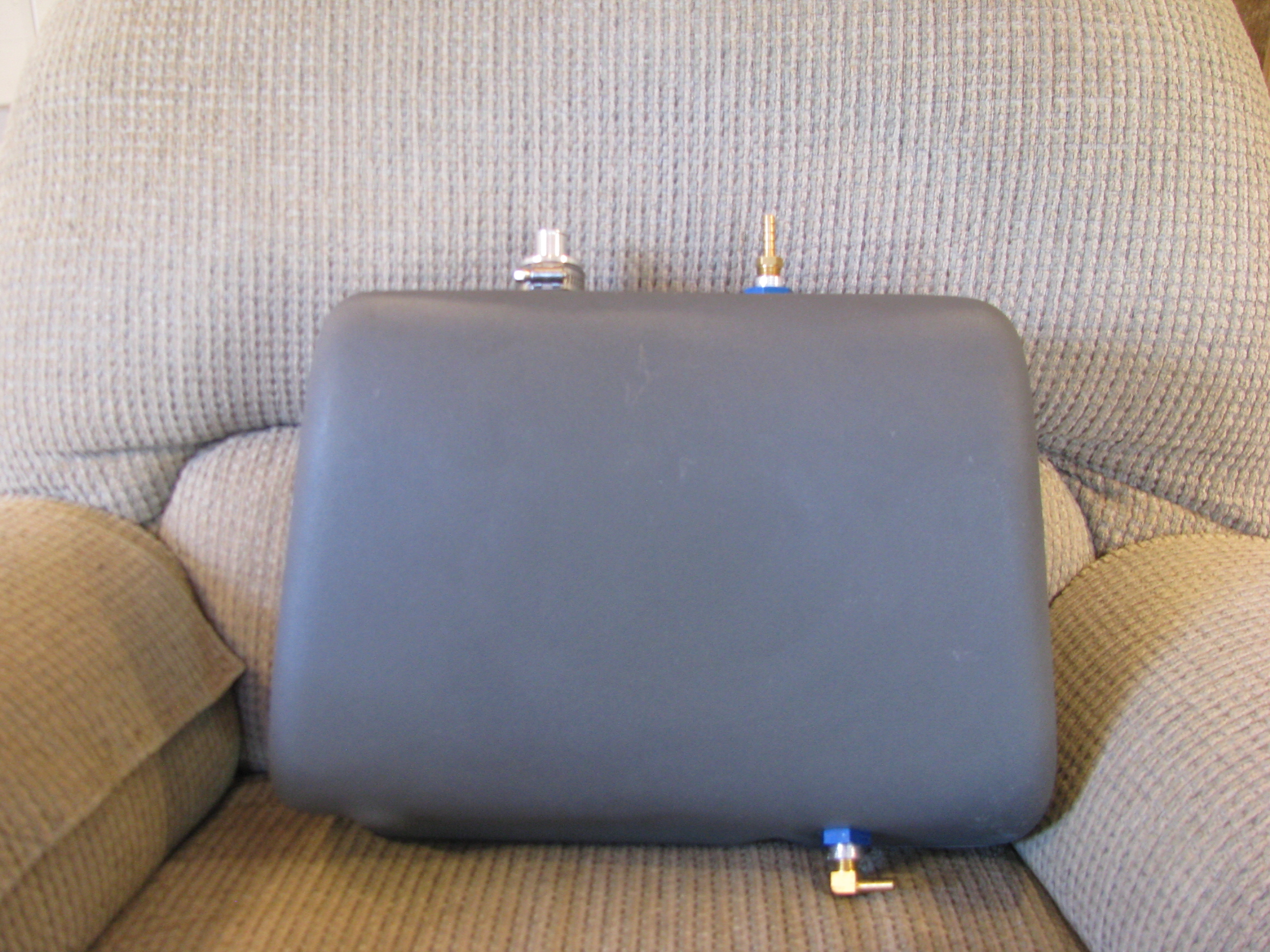
The aux tank is pretty easy. The only trick is that the upper opening (the large one) is not exactly a uniform cylinder. It took a bunch of sanding and trimming for the fitting to be persuaded in and to fit the O-ring securely.
The only issue that bothers me is that in order to screw in the brass fittings I will probably have to clamp the external threads to hold the fittings steady, which is bound to bugger the threads. That will prevent the inserts from ever being removed.
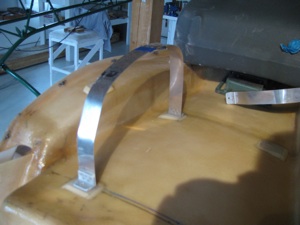
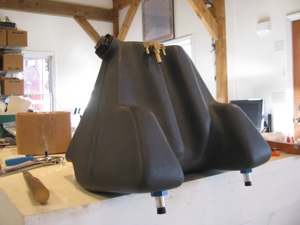
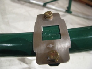
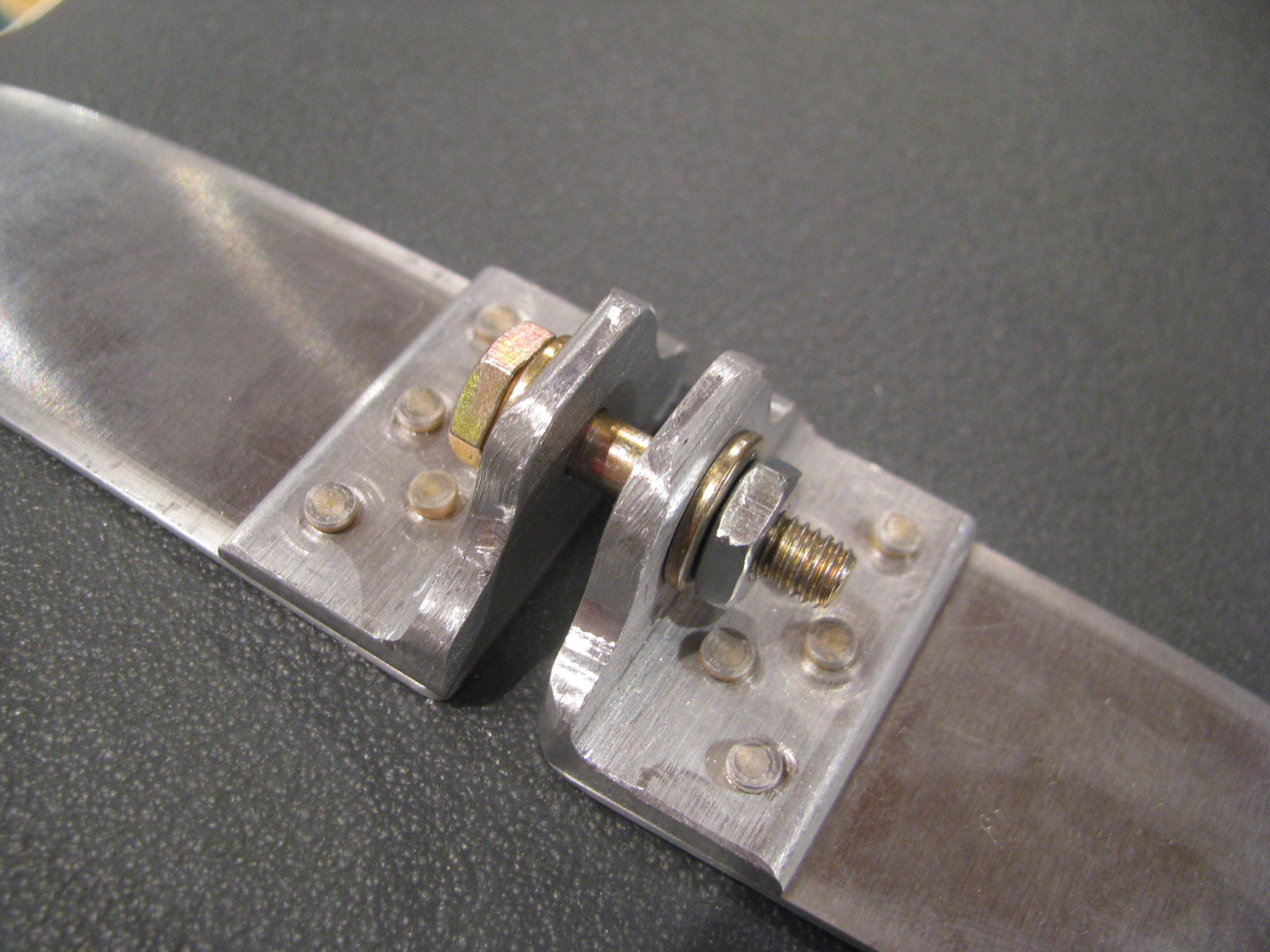
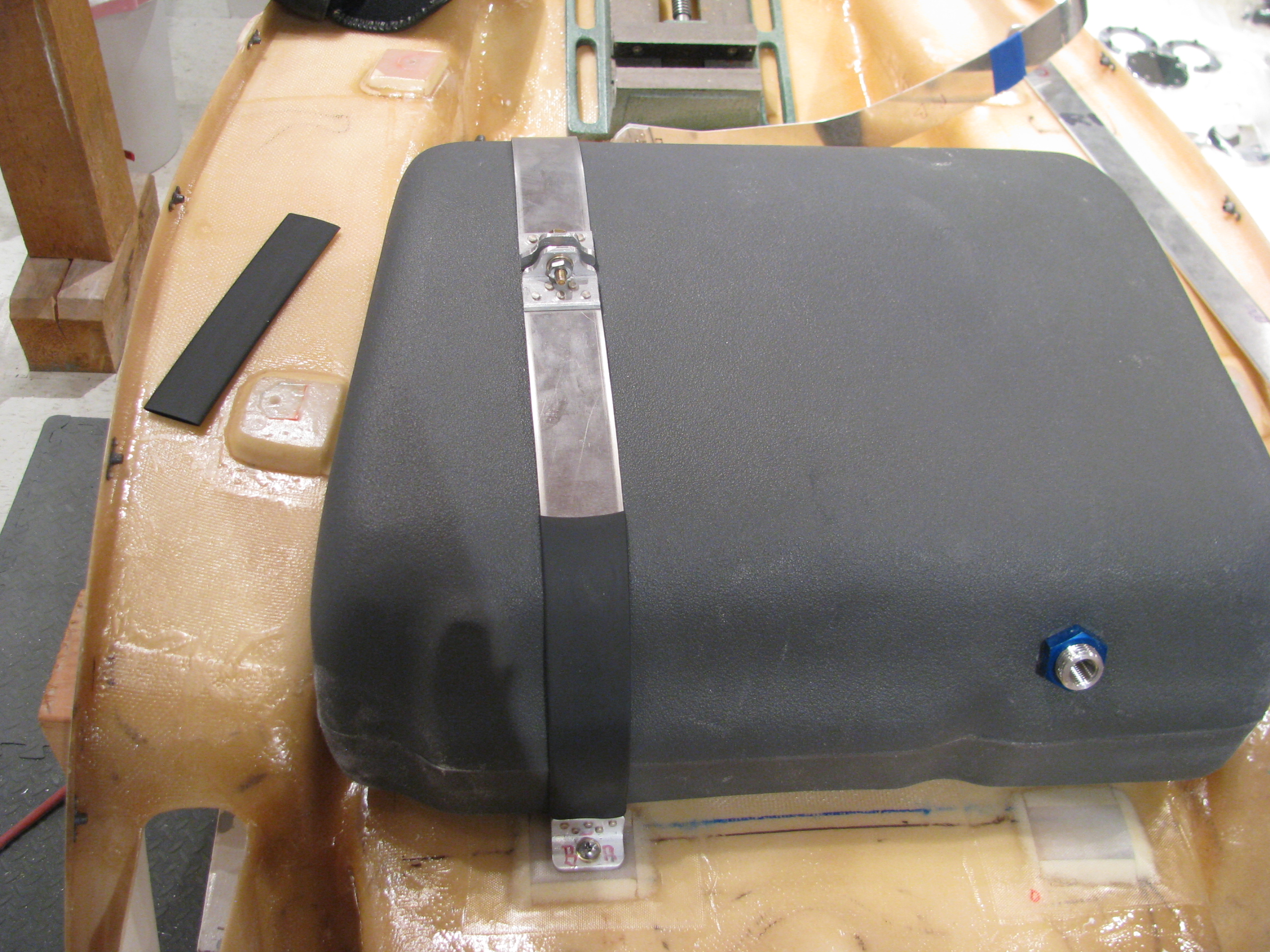
12/1/11 - I set to work fabricating the hold-down straps for the aux tank. I didn’t like the way BJ called for the strap to be simply bent and bolted to the back of the seat. Seemed like there would be a stress point right at the bolt, so I riveted on a couple of pieces of angle to better handle the 90 degree force turn.
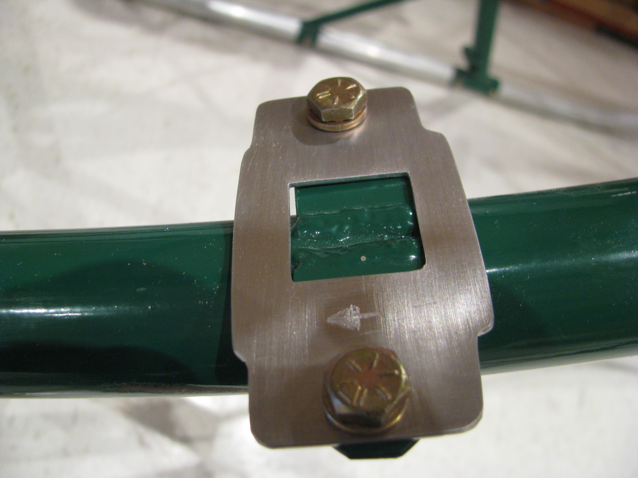
The curve of the seatback also caused the straps to not sit flat, so I glued on some foam strips, poured in some flox, ground and sanded them flat and perpendicular, then glassed over the foam.
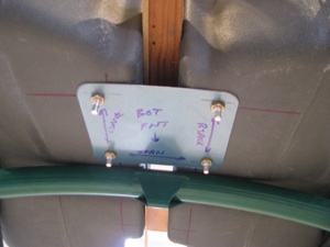
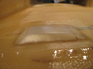
The close up shows a tiny little void in the glass in the lower right, but this is non structural, so we won’t panic. I am learning fiberglass and my results are getting better, but I won’t be building a Long-EZ yet.
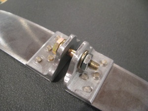
I whipped up these little brackets to allow for snugging down the straps and taking up any excess slack in the straps themselves. Not much weight and it should be easier to make sure we’re tight and not moving around at all.
Using BJs method would be lighter, but you’d have to have the strap length absolutely perfect to have them reach the correct tension right as they bottom out. Probably not possible with the flexing of the tank.

One down. One to go. I need more of this jumbo shrink tubing and to paint them up on completion.
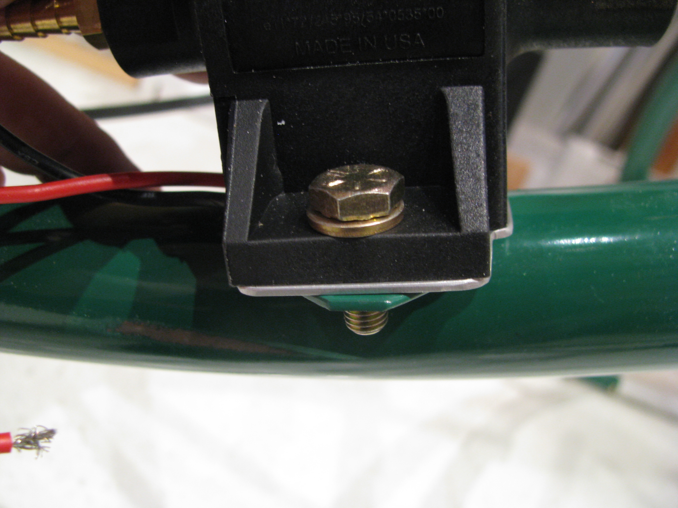
12/31/11 This is the fuel pump mount pad. The welds that mount the tabs to the frame extend up a little. Instead of grinding them down (weakening the joint and breaking the powdercoat) I just made this 0.050 shim in the shape fo the fuel pump base. It’s as thick as the welds and everything sits flat now.
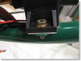
Done for now. The tanks have been preliminarily fit, the hoses have been cut, and everything looks good. I have a fuel flow gauge and sender on order. When they get here I will seal it all up and do a leak check and be done with fuel until final assembly.
One note: I did elect to forego the Westberg sender and gauge since it seemed like a pretty expensive way to only measure the lower tank. I saw a video on the web of one builder who ran a sight gauge in the cockpit along the back interior edge of the seat pan. Pretty primitive, but an effective way to see the real level from the top to the bottom. I am thinking this is the way I’ll go as a gauge of last resort. The fuel flow meter will be primary with the visual sight level as backup.

There are a lot of bits and pieces in many, many bags. I will admit that I did not inventory the fuel system when I took delivery of the kit, but everything seems to be there. So far the only thing I have been missing in the entire kit thus far has been one thin washer back in the mixer assembly.

The top tank is fitted out and drilled. I corked and checked for leaks with water. I plan on pre-assembling the entire fuel system in the ship and leak testing it in its entirety, then remove it all and then setting it aside until final assembly.

Fitting the lower tanks and drilling the spreader plates. I actually fished the little fittings through during the drilling op as they held the tanks more securely than just bolts pushed into position.
Plus, you’re doing this drilling upside down on your back, which is a little awkward.

Fittings all installed in the lower tanks and the holes enlarged. I went ahead and drilled both cover plates. I do not plan on using the Westberg gauge and sender as I plan on using a fuel totalizer. In all the planes I have flown or owned I never use the fuel gauge. Time and total fuel actually used as reported by a totalizer has been far more accurate and reliable.

My Glasair gauges are useless as there is only a small band of gauge movement where they are actually in motion somewhere in the middle of the overall capacity. The totalizer is far more accurate.
Of course the thing you lose is the remote possibility of a catastrophic leak being detected in time to set it down before all fuel has leaked out. I’m willing to accept that.
The aux tank is pretty easy. The only trick is that the upper opening (the large one) is not exactly a uniform cylinder. It took a bunch of sanding and trimming for the fitting to be persuaded in and to fit the O-ring securely.
The only issue that bothers me is that in order to screw in the brass fittings I will probably have to clamp the external threads to hold the fittings steady, which is bound to bugger the threads. That will prevent the inserts from ever being removed.

12/1/11 - I set to work fabricating the hold-down straps for the aux tank. I didn’t like the way BJ called for the strap to be simply bent and bolted to the back of the seat. Seemed like there would be a stress point right at the bolt, so I riveted on a couple of pieces of angle to better handle the 90 degree force turn.

The curve of the seatback also caused the straps to not sit flat, so I glued on some foam strips, poured in some flox, ground and sanded them flat and perpendicular, then glassed over the foam.
The close up shows a tiny little void in the glass in the lower right, but this is non structural, so we won’t panic. I am learning fiberglass and my results are getting better, but I won’t be building a Long-EZ yet.
I whipped up these little brackets to allow for snugging down the straps and taking up any excess slack in the straps themselves. Not much weight and it should be easier to make sure we’re tight and not moving around at all.
Using BJs method would be lighter, but you’d have to have the strap length absolutely perfect to have them reach the correct tension right as they bottom out. Probably not possible with the flexing of the tank.
One down. One to go. I need more of this jumbo shrink tubing and to paint them up on completion.
12/31/11 This is the fuel pump mount pad. The welds that mount the tabs to the frame extend up a little. Instead of grinding them down (weakening the joint and breaking the powdercoat) I just made this 0.050 shim in the shape fo the fuel pump base. It’s as thick as the welds and everything sits flat now.
Done for now. The tanks have been preliminarily fit, the hoses have been cut, and everything looks good. I have a fuel flow gauge and sender on order. When they get here I will seal it all up and do a leak check and be done with fuel until final assembly.
One note: I did elect to forego the Westberg sender and gauge since it seemed like a pretty expensive way to only measure the lower tank. I saw a video on the web of one builder who ran a sight gauge in the cockpit along the back interior edge of the seat pan. Pretty primitive, but an effective way to see the real level from the top to the bottom. I am thinking this is the way I’ll go as a gauge of last resort. The fuel flow meter will be primary with the visual sight level as backup.