
Jack Table
The engine went on the floor and I modified the cradle so I could just hoist it straight up and out.
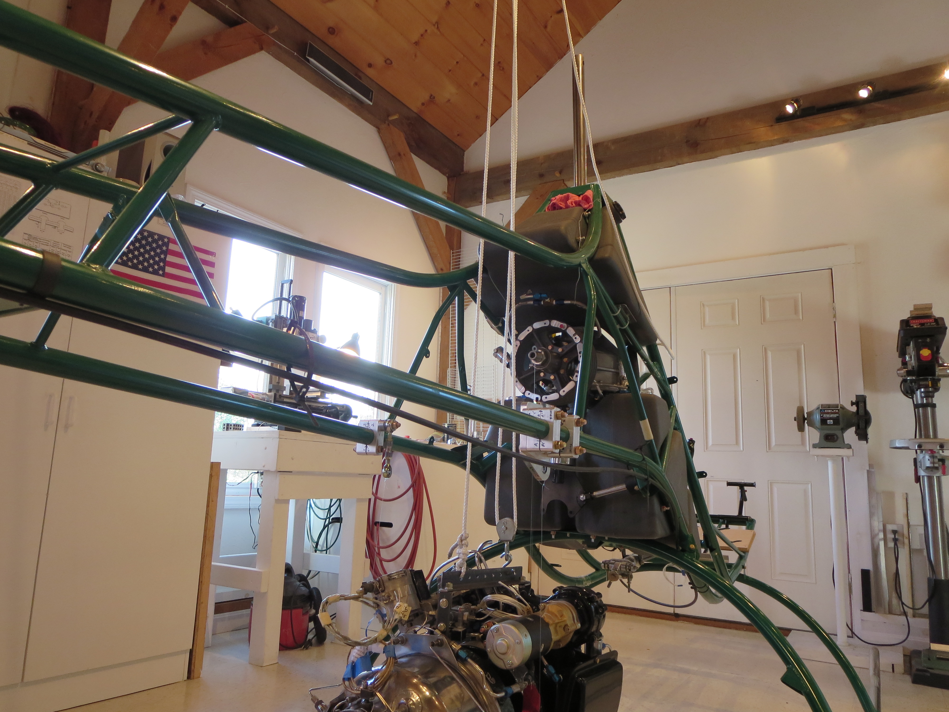
Then I tried lifting the engine with my pulley system. Two problems; 1) The rope was quite stretchy. I can't imagine trying to position the engine precisely with this system., and 2) Seeing the engine dangling from a few thin strands was too nerve-wracking. That's 10-15K worth of turbine swinging on some home-depot rope.
It probably would have been fine, but between the swinging and the tough precision thing I knew I wanted to do something different.
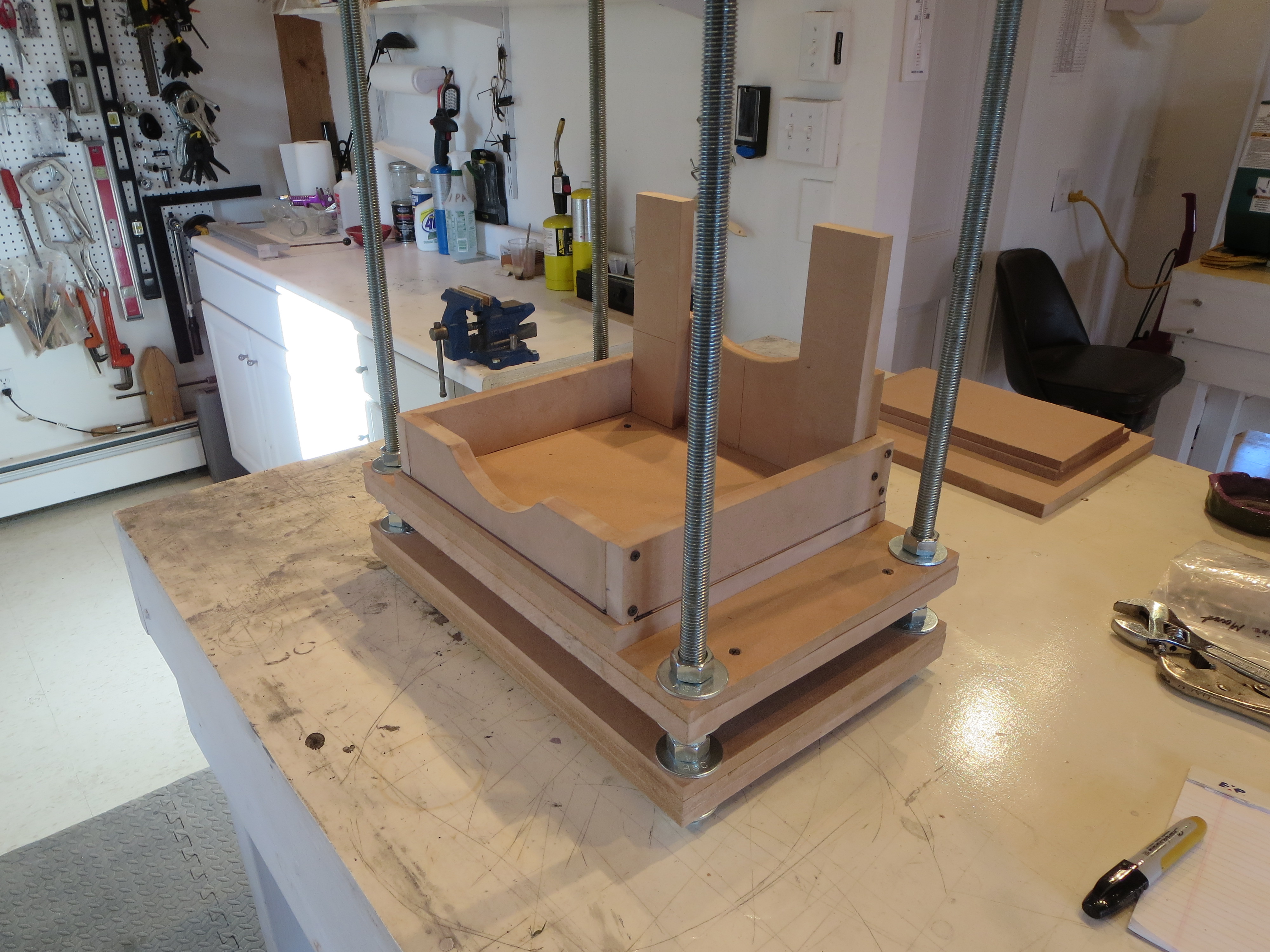
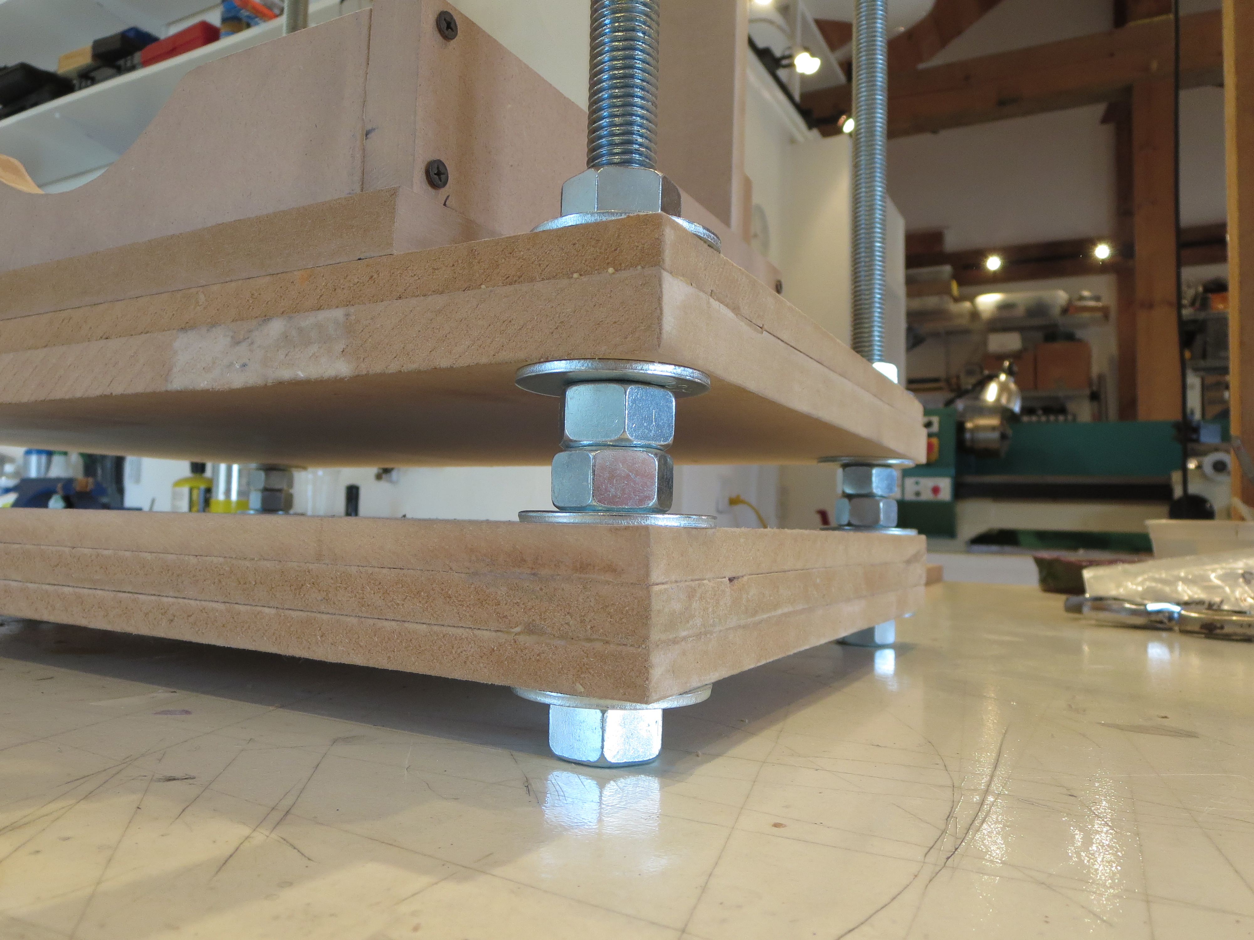
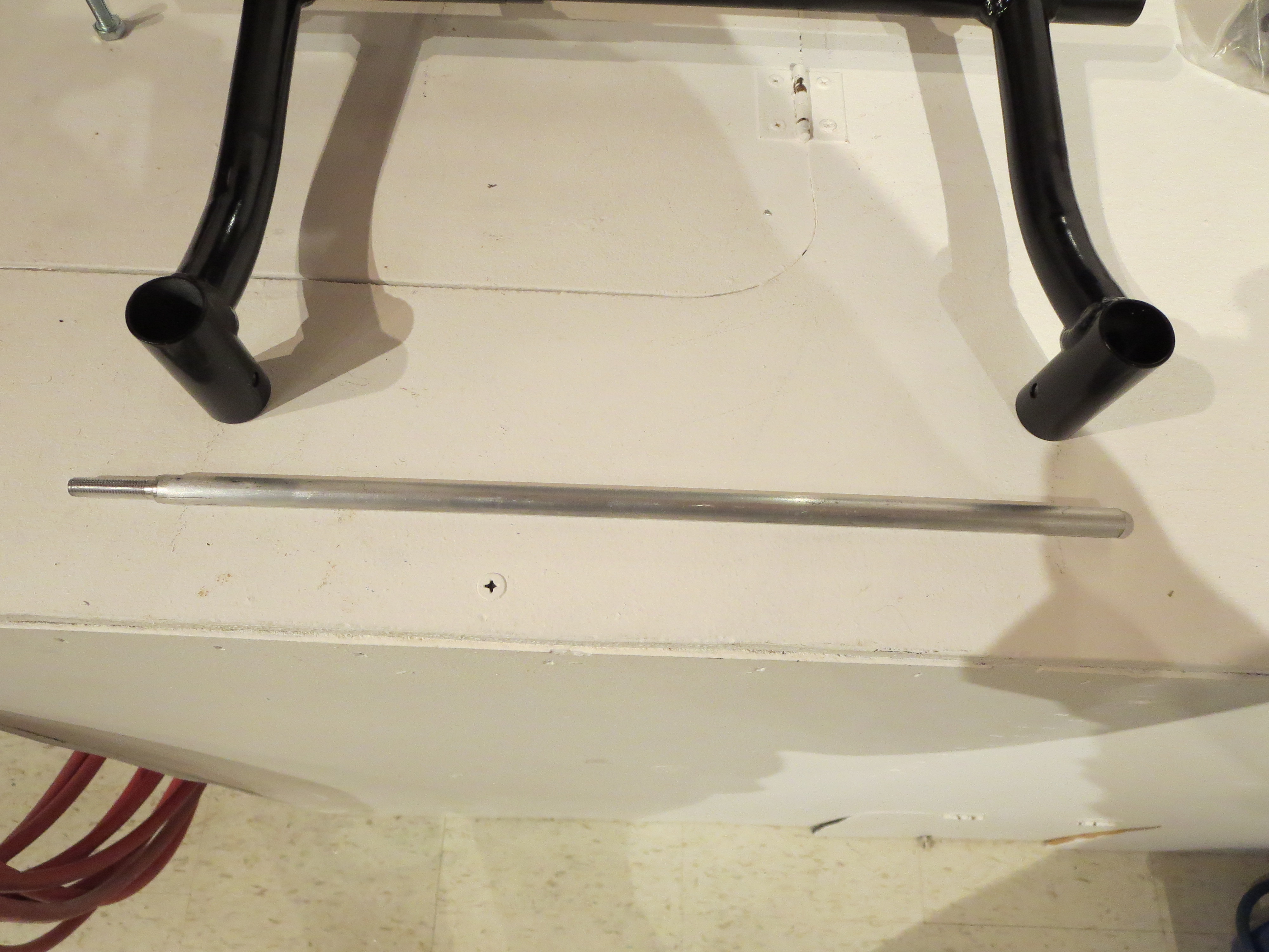
So I went to Home Depot and picked up some 3/4" threaded rod,washers, and nuts. 3/4" is certainly way overkill for the engine's weight, it's more for the stiffness so I don't need much more structure to keep the torsion and twist under control. I had a ton of MDF pieces left over from my CNC router project.
I made a new cradle for the turbine and added another thick interim layer to keep the whole thing stiff.
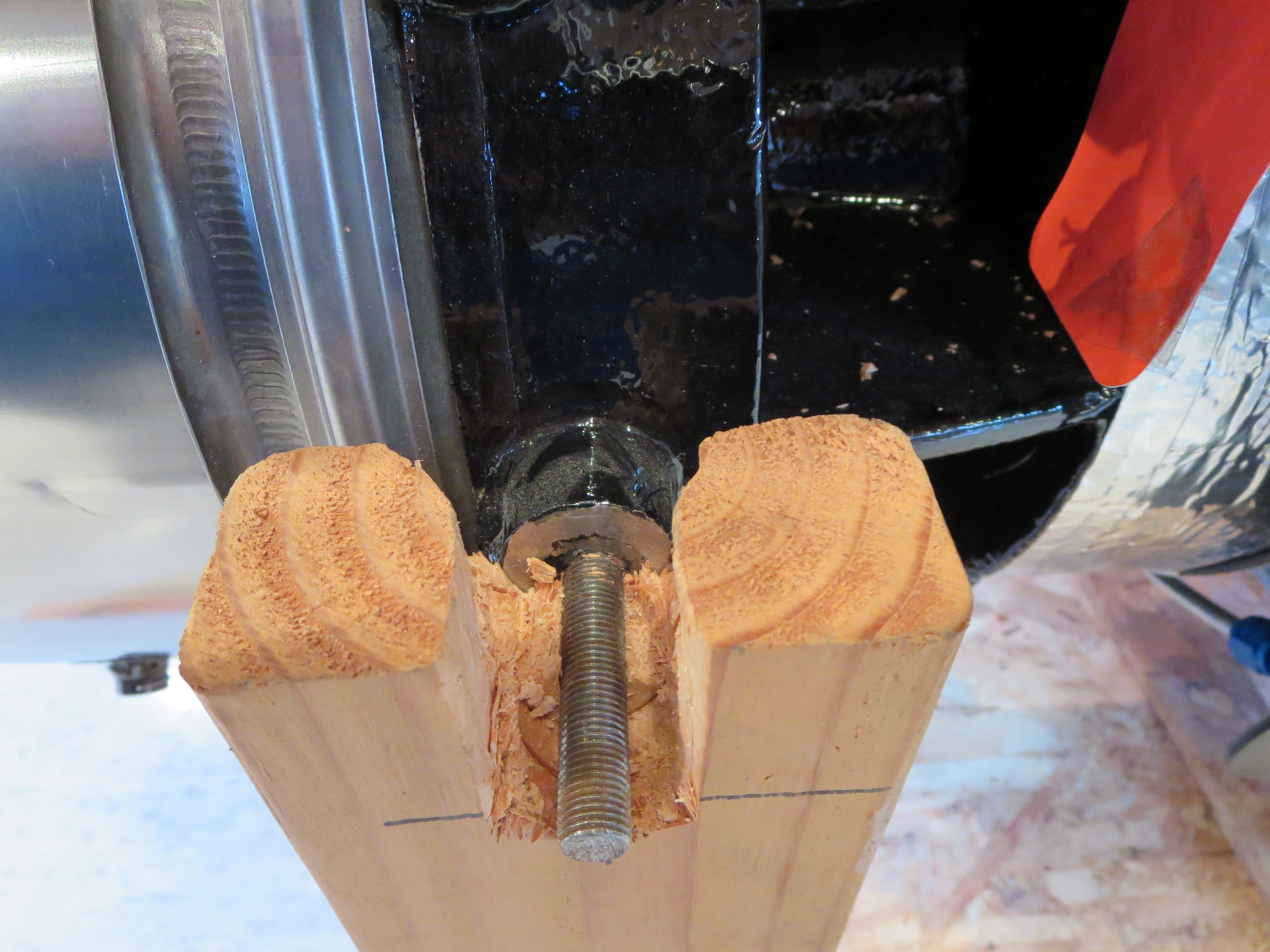
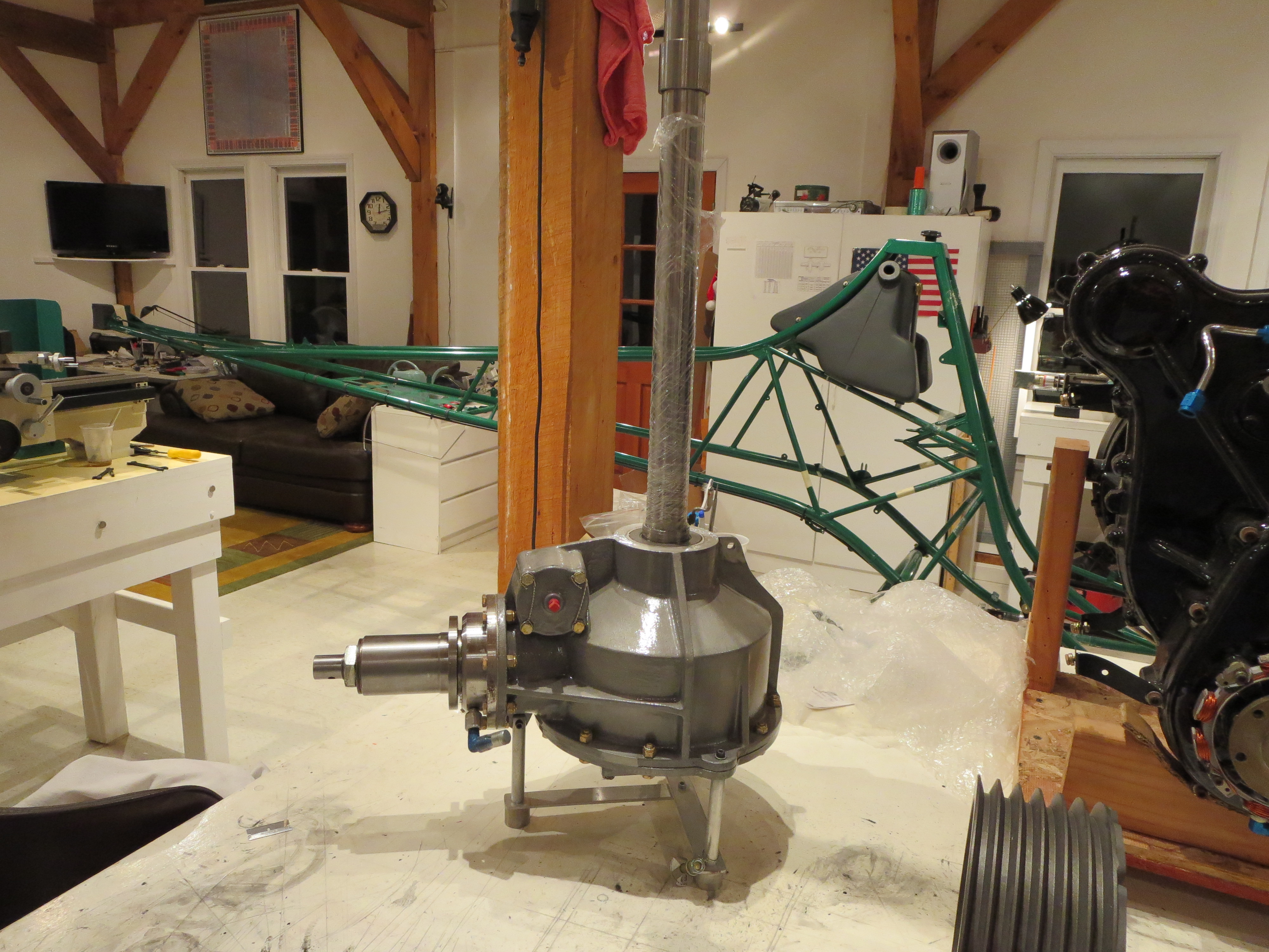
The idea is to transfer the turbine over to this jacking table and use the nuts to incrementally raise the engine up. Should be very safe and allow for very precise positioning.
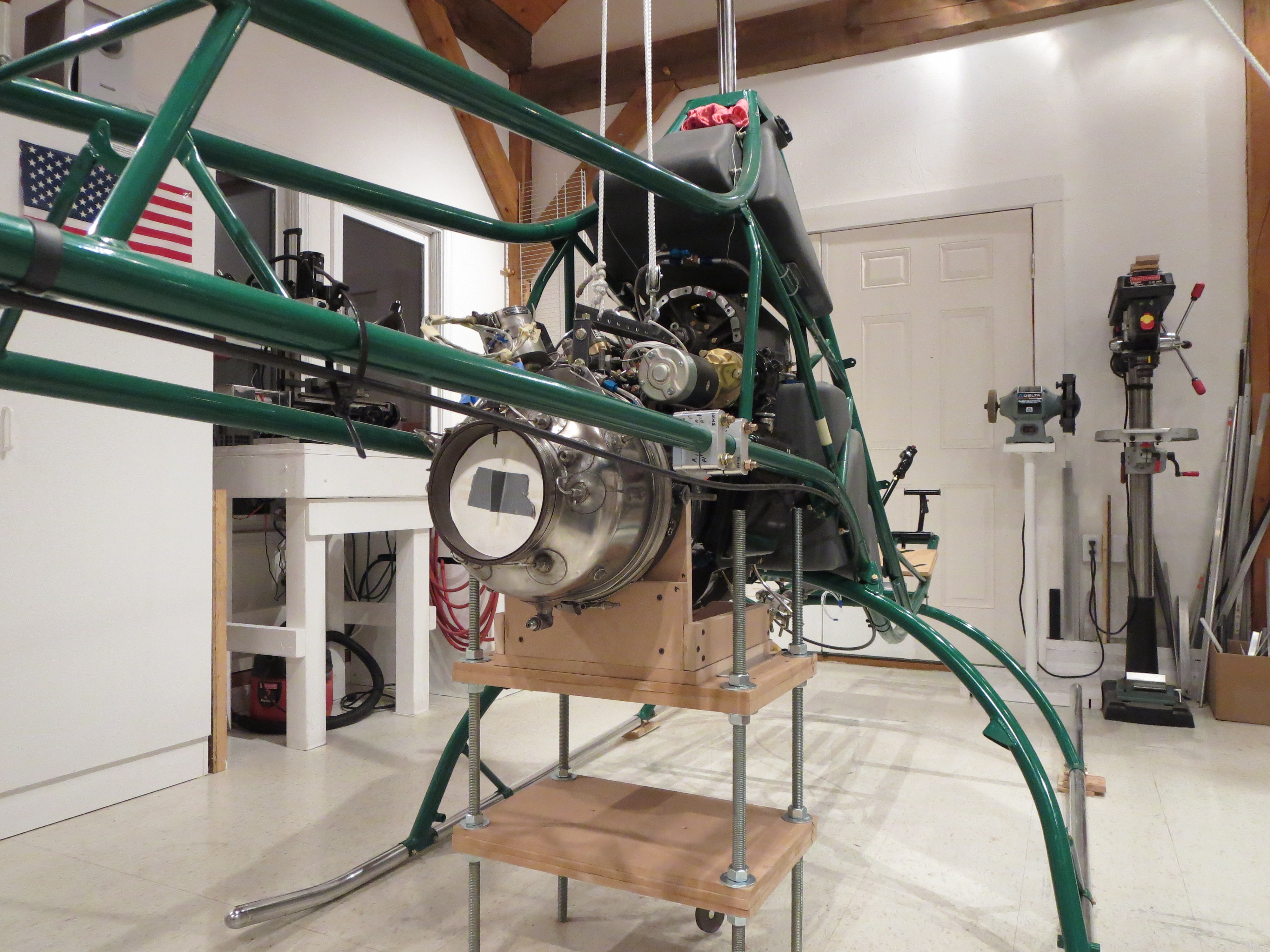
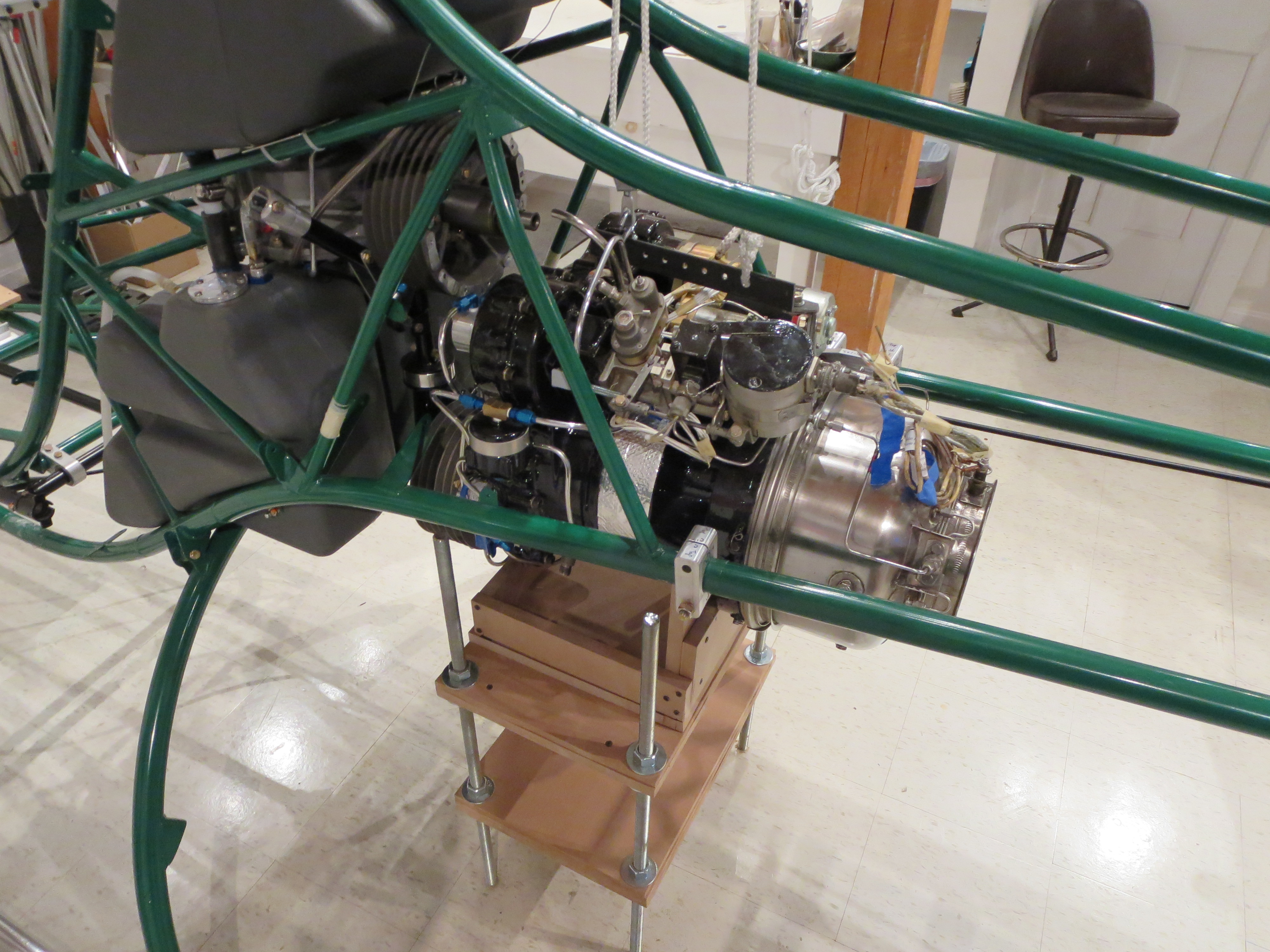
So here is the turbine in position after incrementally jacking it into position. It's very stable and certainly not going anywhere, so I can fiddle with alignment all I care to before locking it down permanently.
HERE is the whole process of building the table and jacking the turbine.

Of course after taking the photos and staring at it I realize I forgot to put the belts on so I will have to lower it a couple of inches and slide the belts on.
Blades are Back
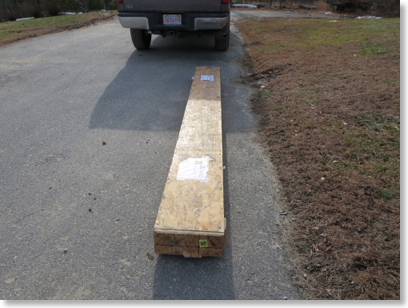
I went to pick up my blades from Conway Freight today. They are back and they have been machined. All I have done is crack the crate and have a peek.
There are no more excuses standing in my way of completion now.
Shop Day
The camera has the ability to monitor for motion, and then push images to an FTP server every second when there is motion detected. I then use an application called "Time Lapse Assembler" to string them into a movie.
Here is a day in the shop. The only frames logged are when I am in view and there is enough motion to trigger the camera, so it is not a full day, but several hours worth. Still, it's pretty big if you chose to download it.
This will get more interesting when there is more action on the airframe. Most of this is engine prep work. With a low-resolution video camera like this it makes for a pretty boring video. I will remedy that soon enough.
Tasks accomplished on camera:
- Safety wiring some engine fittings
- Doing the last bit of engine wiring.
- Torque sealing a bunch of bolts (my way of indicating completion)
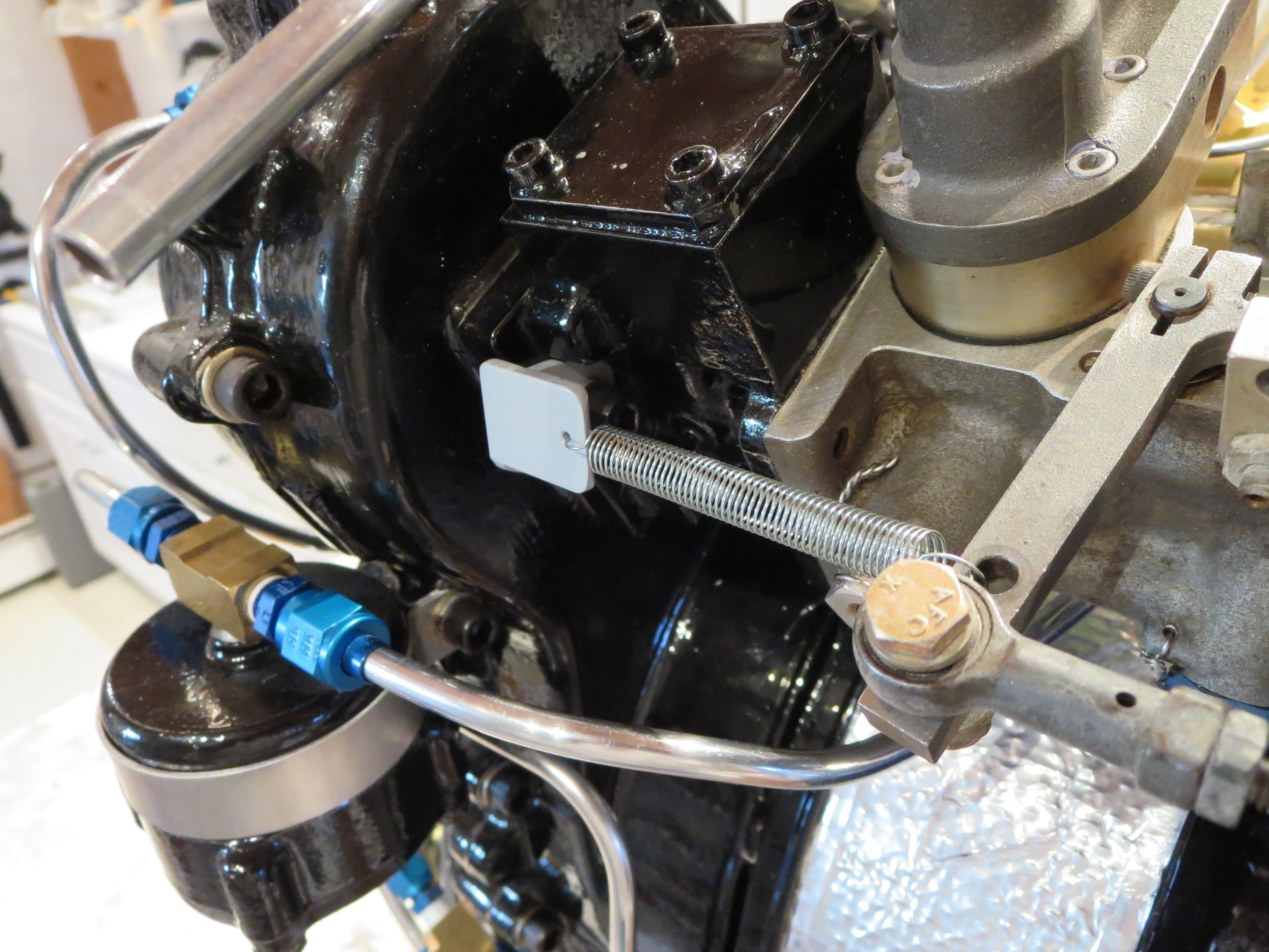
- Fabricating, painting and installing a bracket for the throttle return spring
- Checking the clutch travel and figuring out how it mounts in the ship again.
- Replacing the skid bolts with AN HW of the proper length (the kit-supplied Grade 8 bolts ones are too short).
- Prepping the rubber clutch mount
Engine Prep

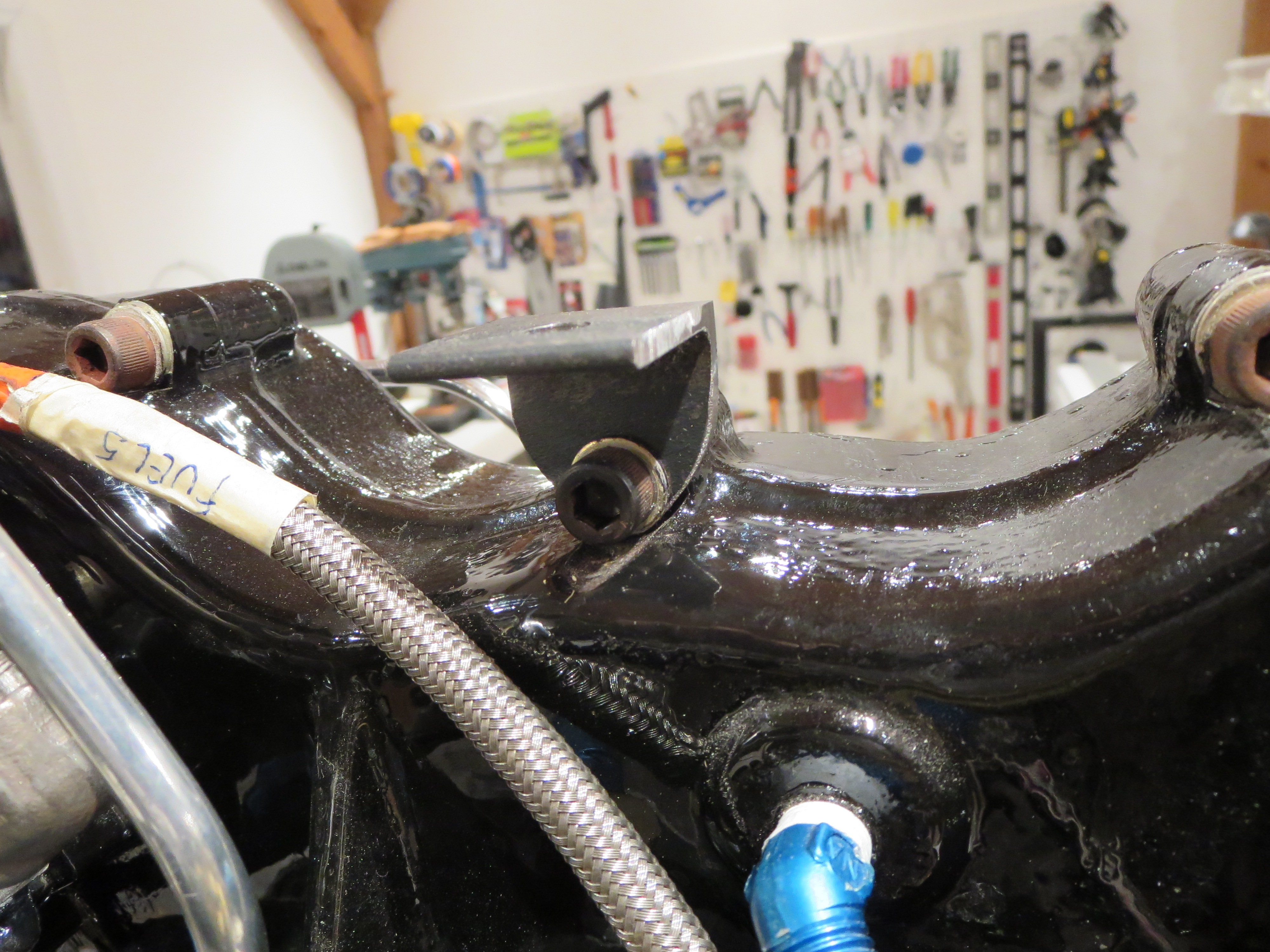
You have to fabricate a little bracket to attach the throttle return spring. I have seen Helicycles that just use a piece of angle here. Well, I shaped and sculpted that stupid little piece way more than necessary.
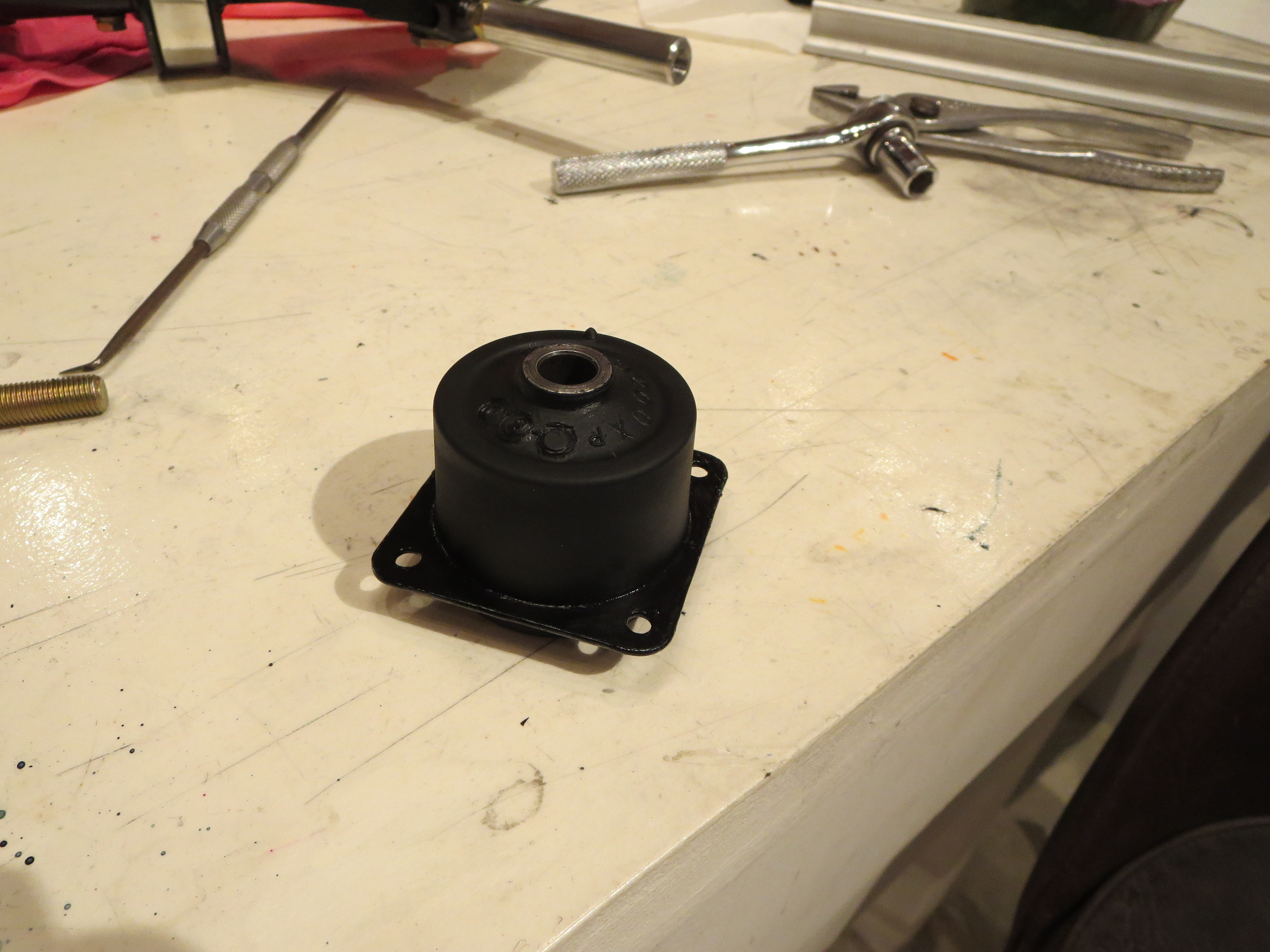
To prep the rubber clutch mount I coated it with Vaseline to loosen the mold-release skin, then rubbed it off the rubber, painted the metal plate (with diluted black nail polish for quick drying), then coated and soaked the rubber in Armor-All to keep the rubber "supple", and lastly coated the bore of the bushing with Corrosion-X. Again, probably overkill since I am sure many just bolt the darn thing in the ship without bothering with any of that.
If you take a half-full bottle of nail polish, top it off with acetone, and shake it up really well, you get a quick-n-dirty lacquer paint. It dries hard as soon as the acetone flashes off. It is not rugged, nor pretty, but for a quick corrosion inhibitor, it saves a ton of time versus real painting.
Engine Hoist Bracket
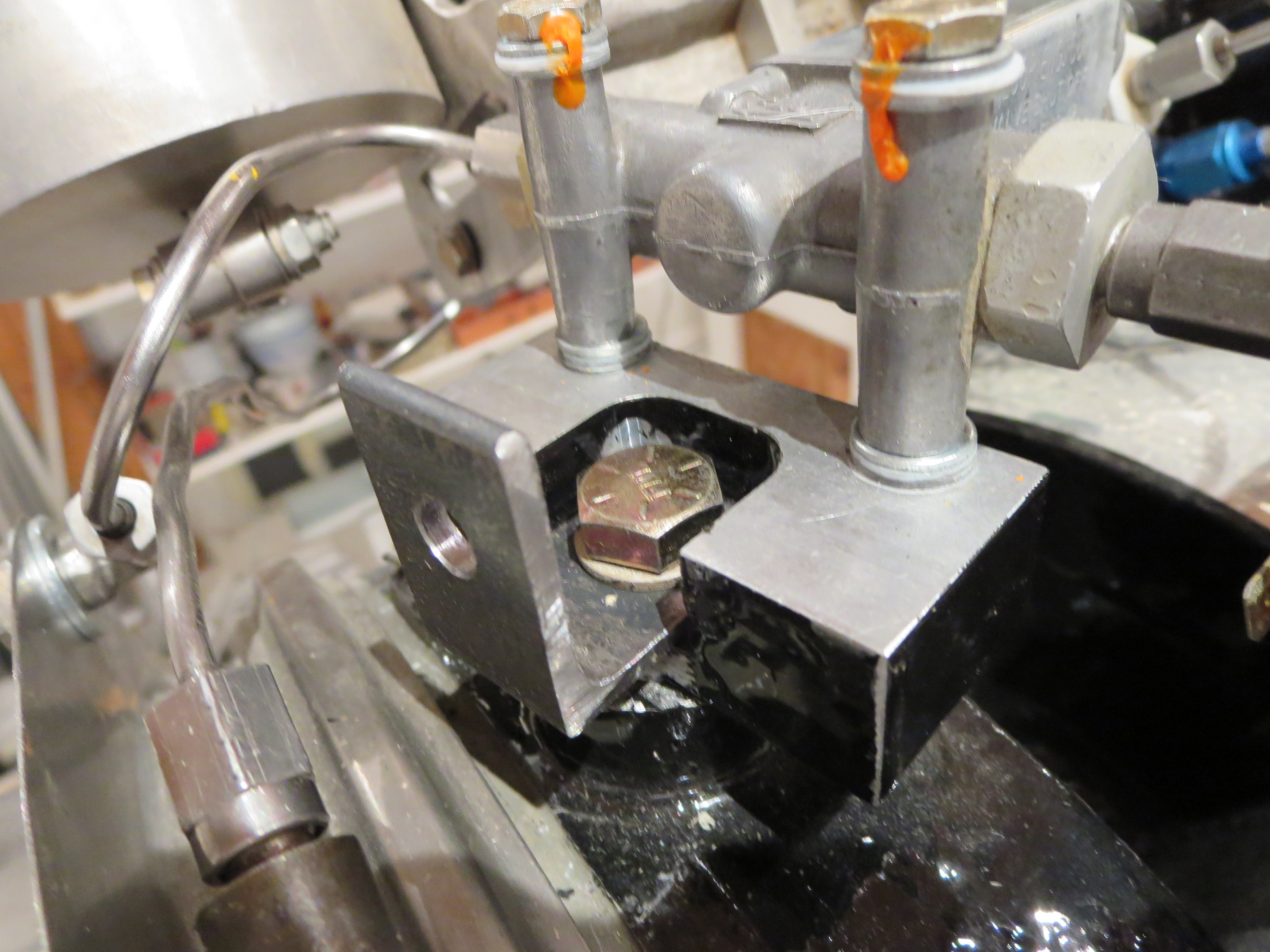
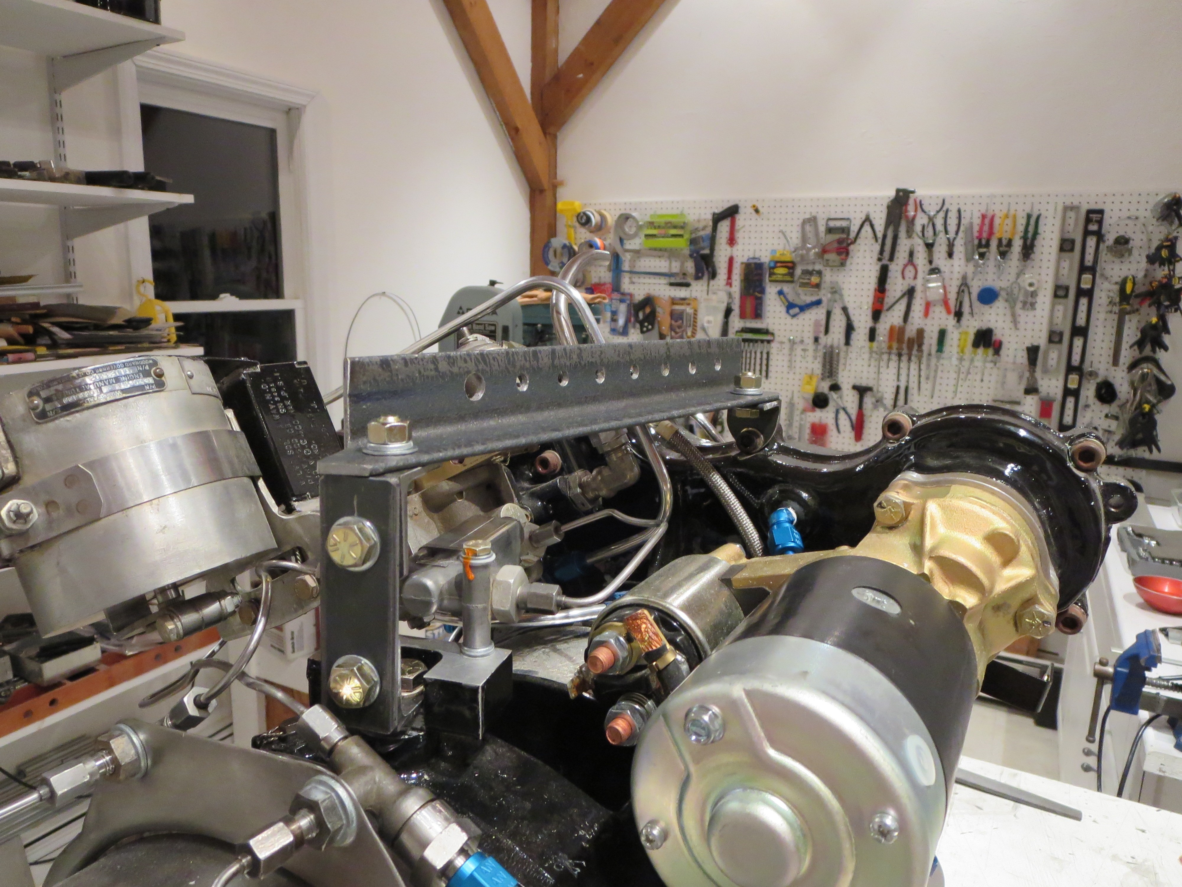
That's just some hardware store GR8 bolts and angle iron from Home Depot. I had forgotten just how nice steel is to work with. Drilled a bunch of holes since I do not know where the CG of the engine is. This way I can just hook on the closest balance point. If this were a permanent thing I would have used more and better mounting points, but it is a single-use, single-function item.
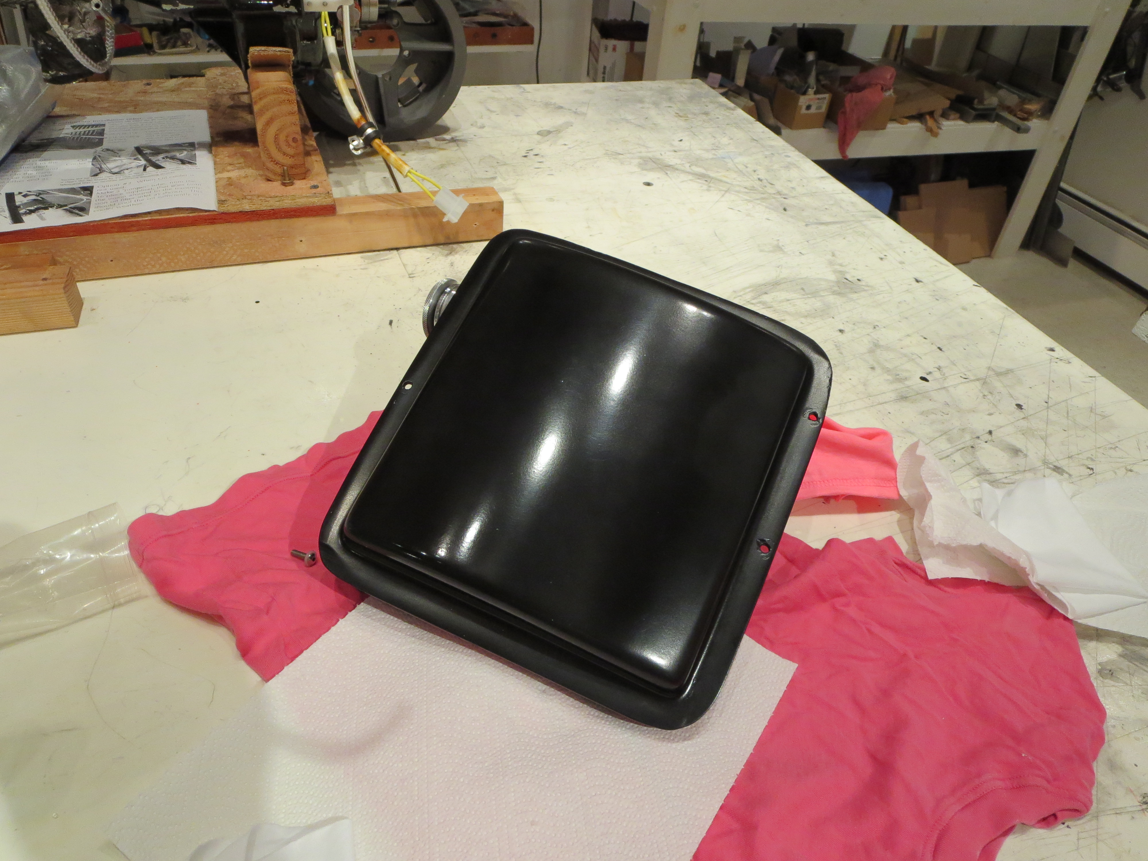
Oil Tank Buff
Engine Mount Prep
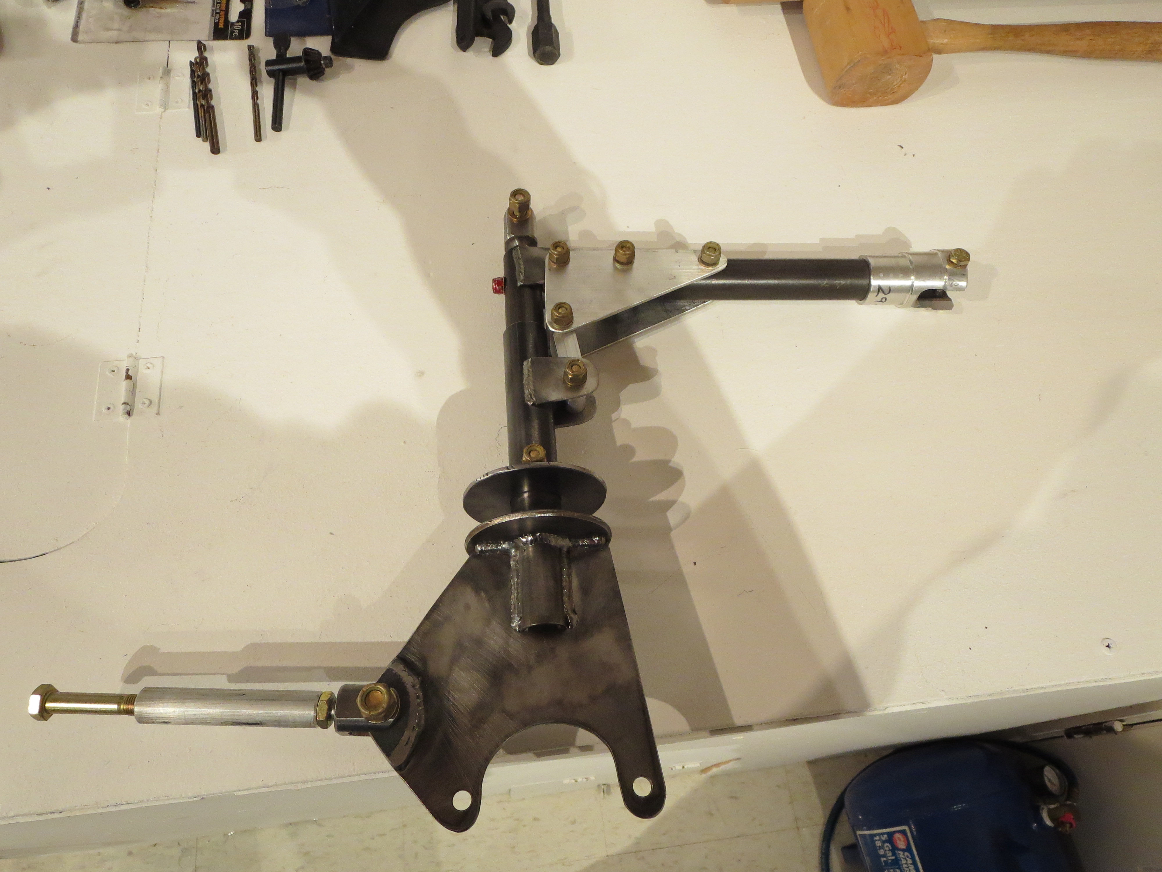
Here are the assemblies for left and right fit together.
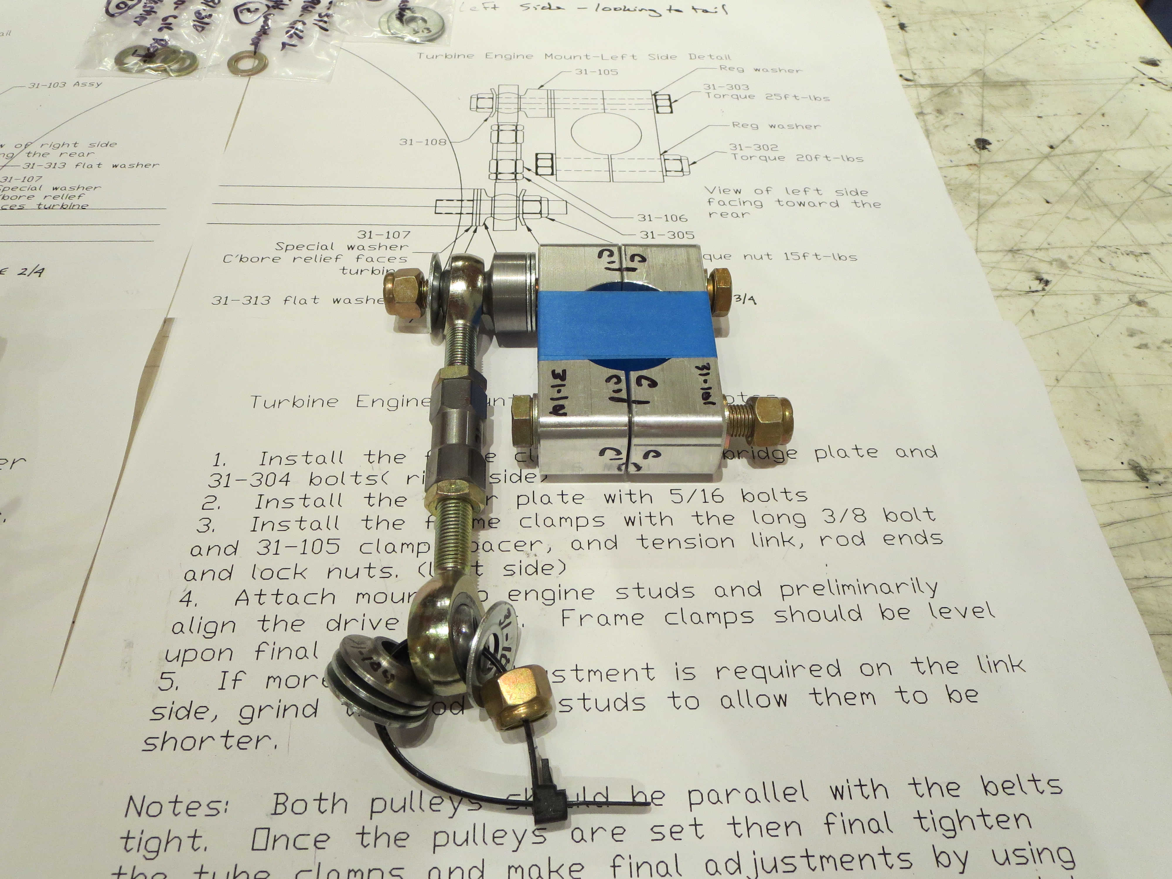

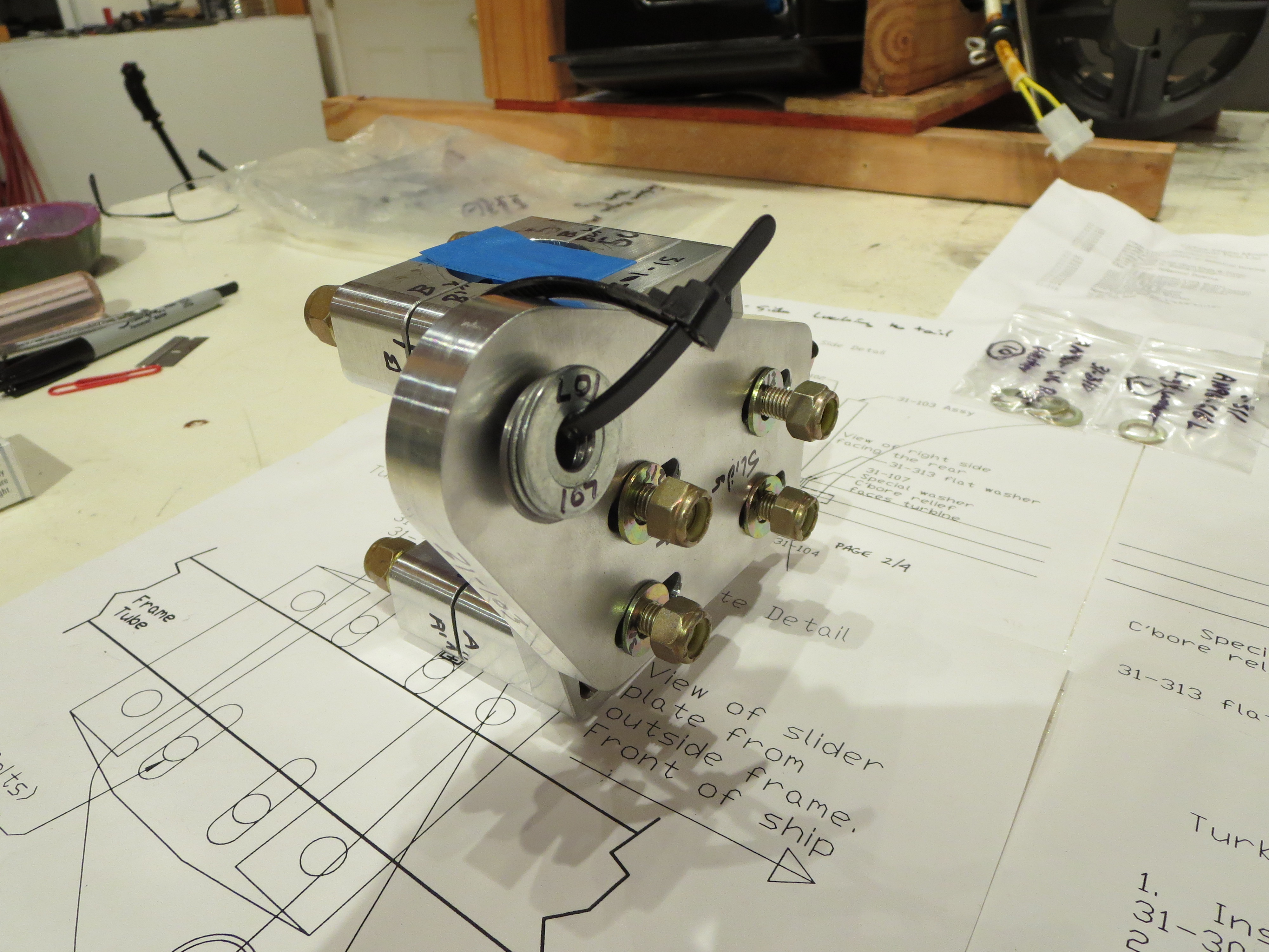
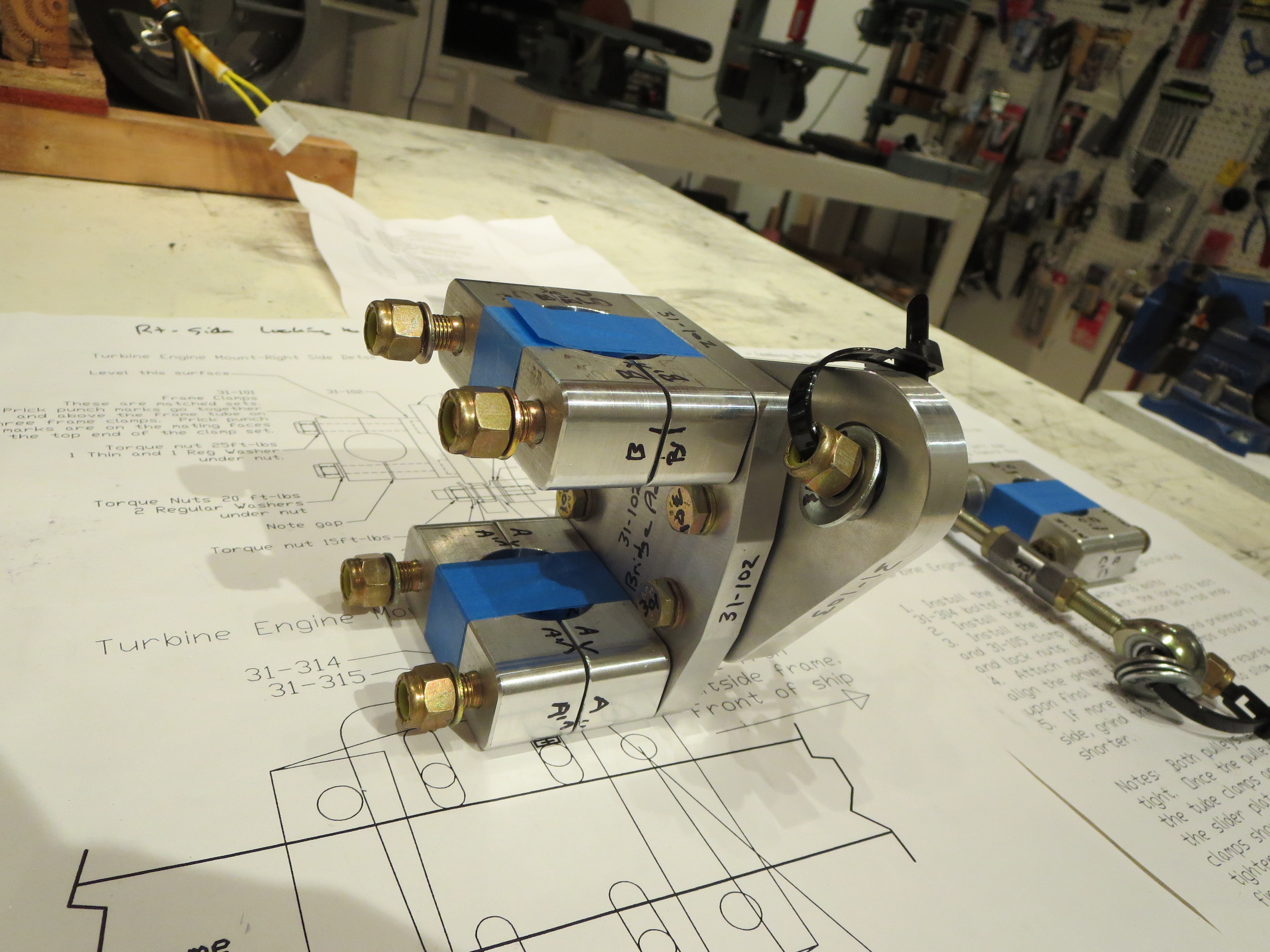
I have a question for Blake as to which way to install the bolts for the inner slider plate on the left side mount; nuts in or nuts out.
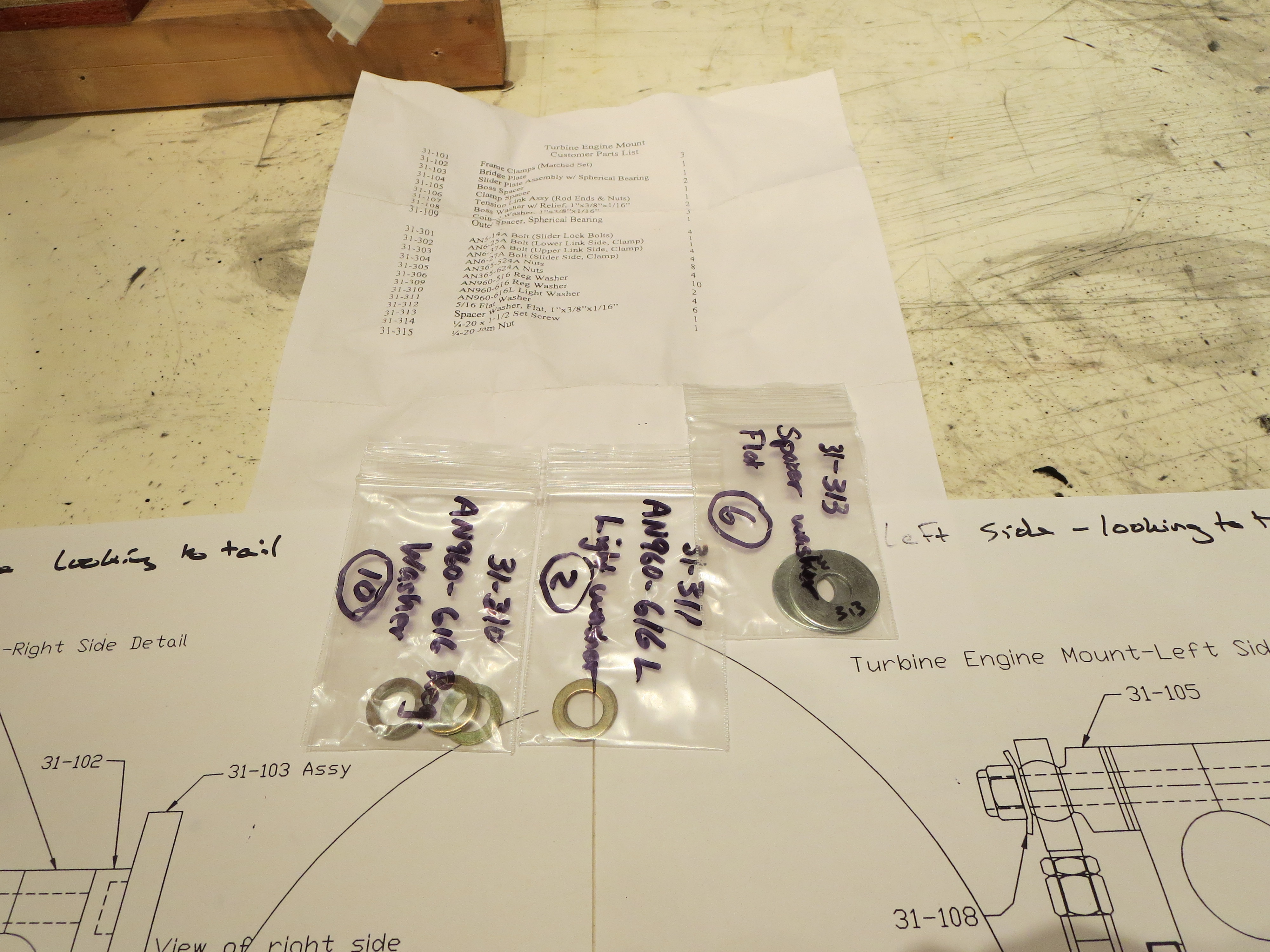
There are a few spare parts, all washers. I am assuming those are for proper spacing once the unit is installed in the ship.
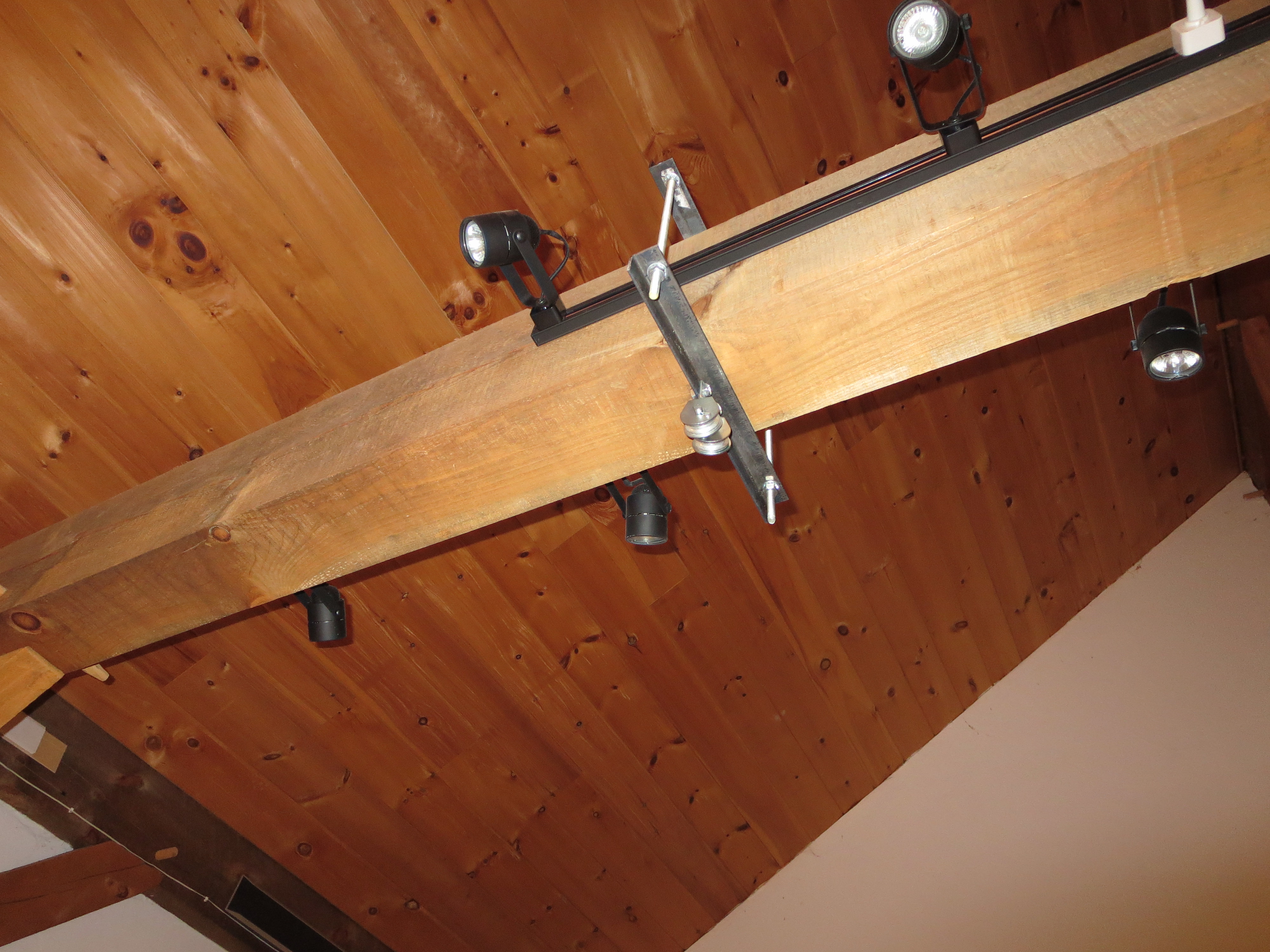
I mounted a couple of heavy steel angles and pulleys to a large beam in my shop for winching the engine up into position.
Next up is to check the gear (since major weight will be on it now), and complete the wiring of the engine, then the mounting starts.
Pulley Balancing

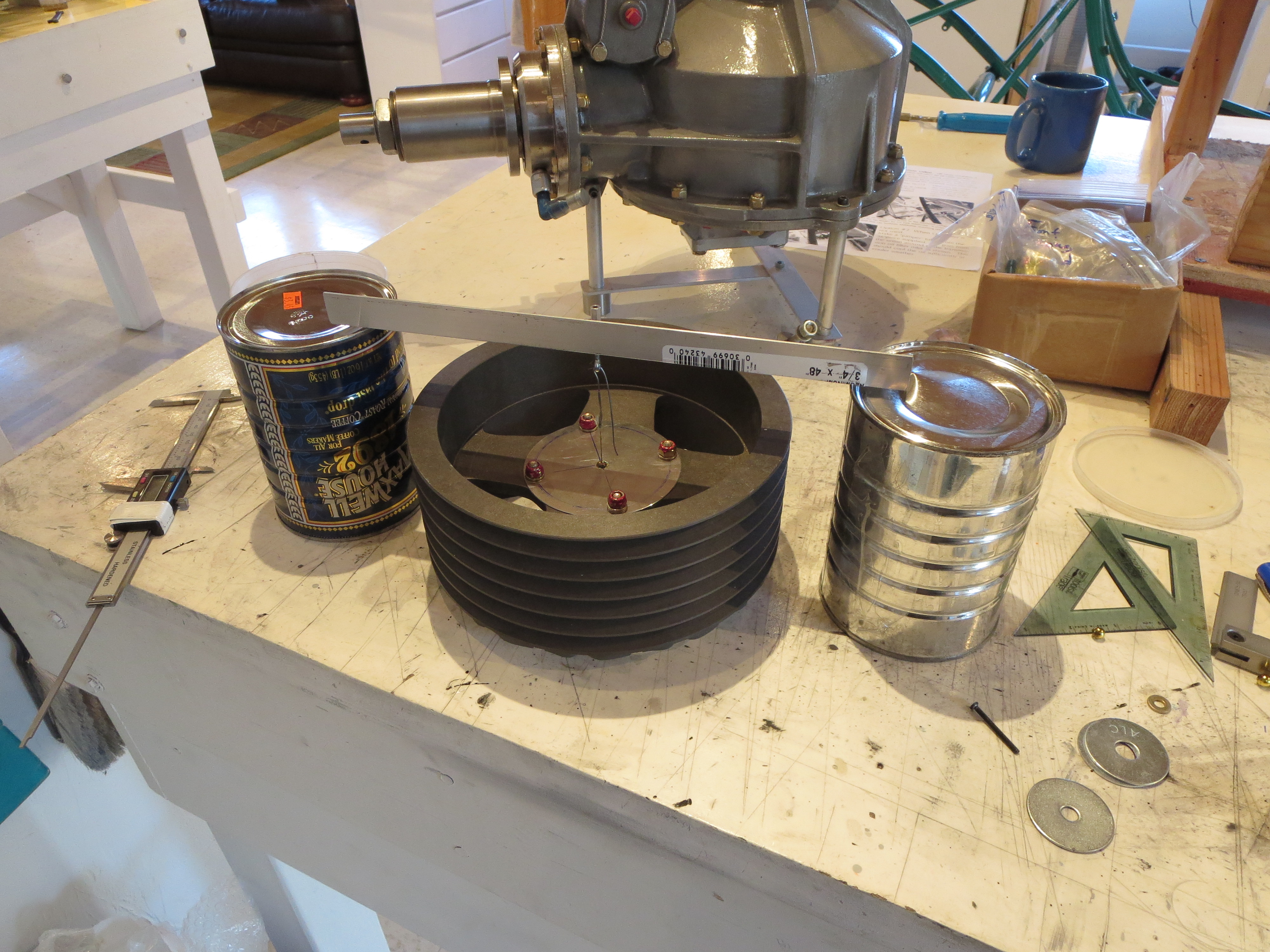
So I built a balancing jig. It's sized for the main transmission pulley and pretty basic. Some heavy stock for the sides and base and two sections of stainless steel ruler (Harbor Freight $1 items) for the "knife edges" sanded and polished on the edges.
The carrier is an "almost" square block. I measured and drilled the bolt holes for the pulley flat face as precisely as I could (again, the mill with DROs is a godsend). All holes are +/- 0.002" of their ideal position. The center spindle is a piece of 4130 steel tubing. I drilled the center hole slightly undersized and sanded up to a super snug press fit. Once pressed in the tubes were sanded and polished.
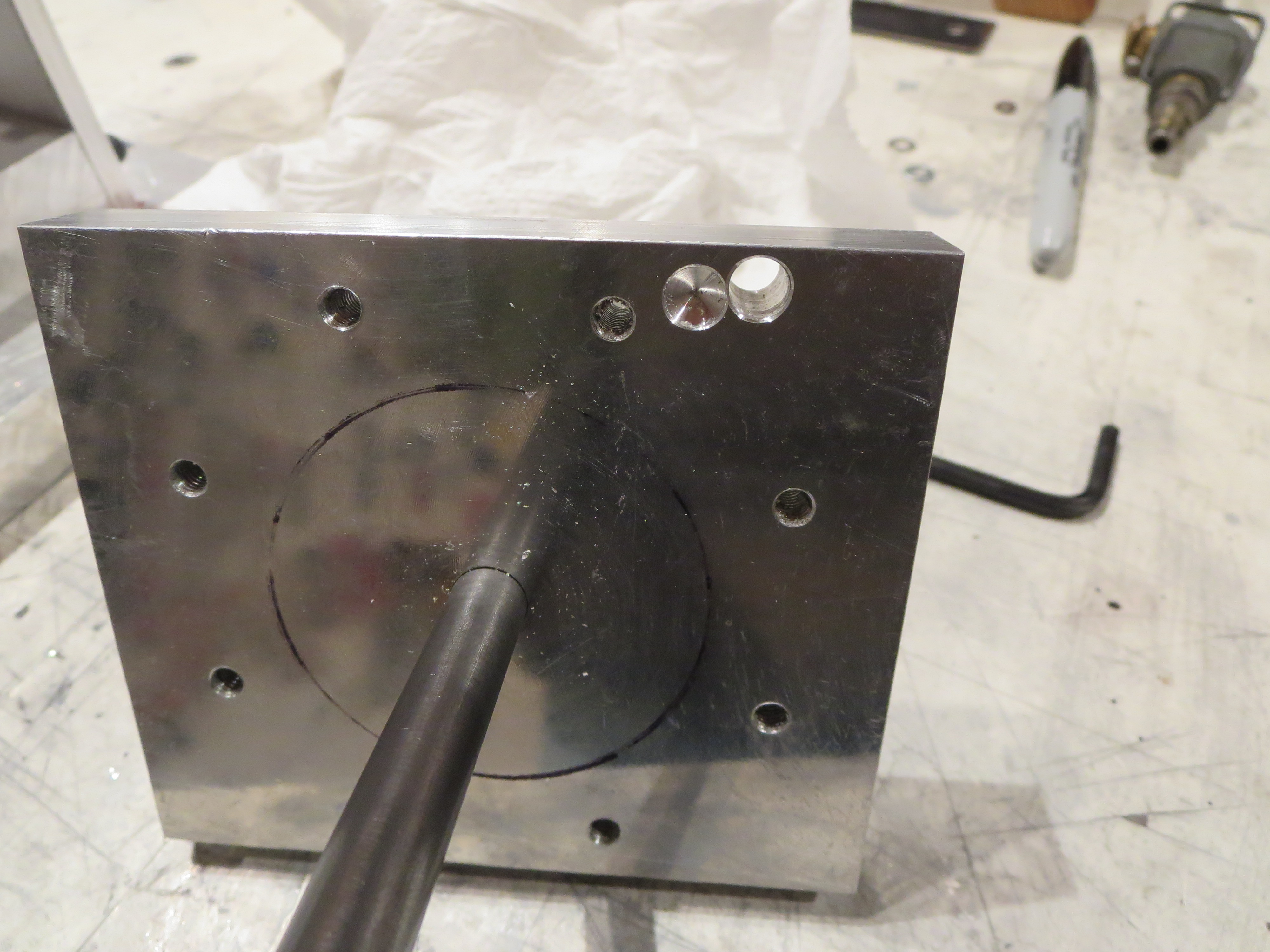
Next, the carrier assembly itself has to be balanced as perfectly as possible and the jig leveled. The through hole and the partially drilled hole achieved that balance. There were already some partially drilled holes on the other side of this block, and the drilling ops are not perfect, no matter how carefulIy it was machined. This is a very important step. When the carrier spindle is balanced you can level the jig with shims to be perfectly level. Even the tiniest of differences causes the balanced item to roll off one side or the other. It's pretty impressive how delicate/accurate this thing is.
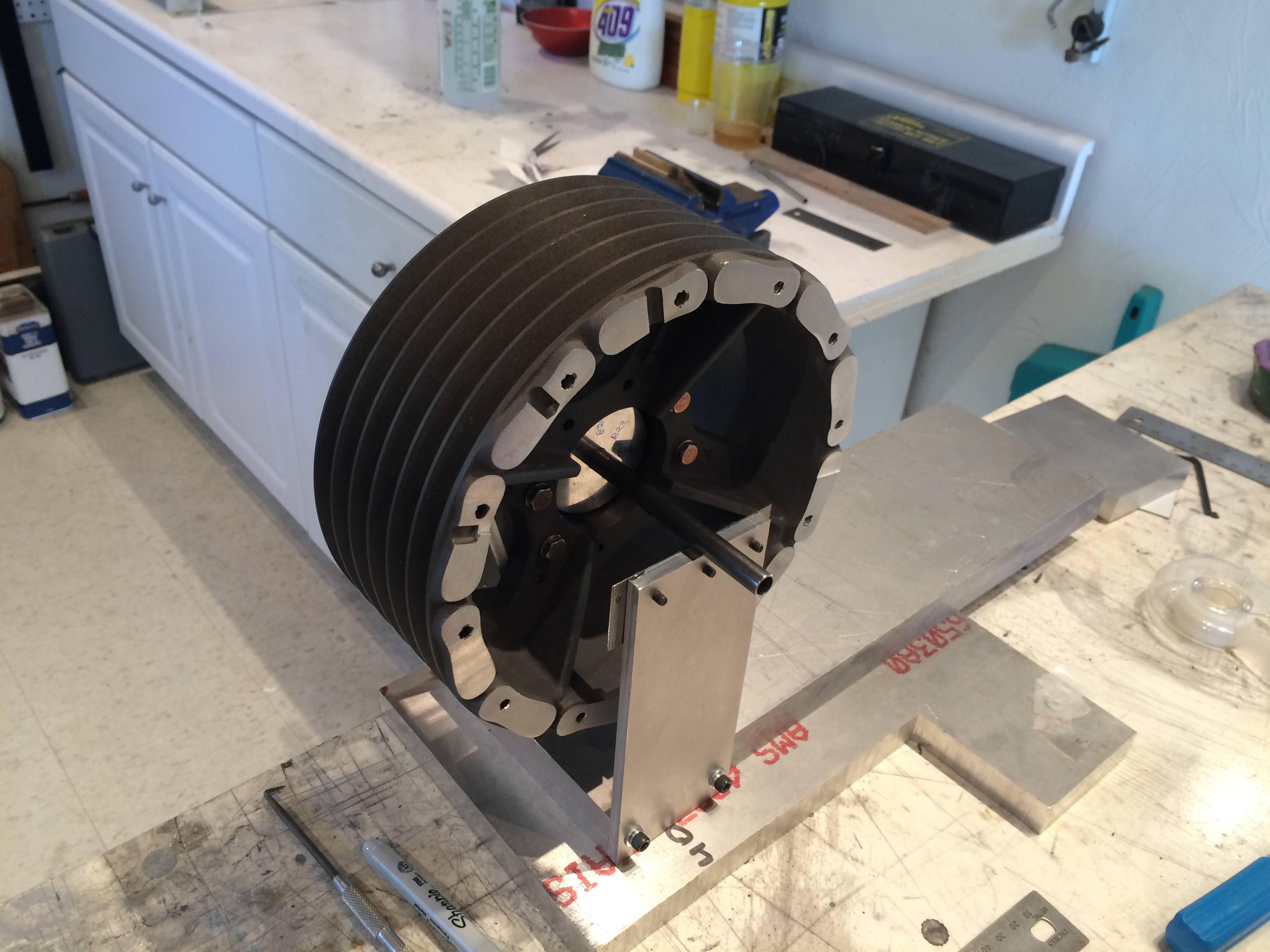
Only THEN can you start balancing the pulley. Bolt it together, see which side is down, mark it, redo the measurement with the carrier at 4 90 degree points, then draw lines across the face of the pulley. The center intersection point is the center of gravity. Since the carrier is not perfectly centering, you must do four measurements at the cardinal points and then draw the centroid. Only THEN remove material on the heavy side - a little at a time - then repeat.
It took several hours, but I am quite satisfied that the balance is WAY better than anything achieved taking the pulley right out of the box, especially if you bolted those hand-cut cooling fins on. I am pretty sure it is now within a gram or two of perfect balance.

Bolted, torqued, and torque sealed in the ship for the last time! Another "final assembly" thing down. On to the engine!
Last SP Priming

I also spent a whole lot more time tweaking the gun for a good spray pattern and quantity. This is kind of a matter of feel as much as anything else.
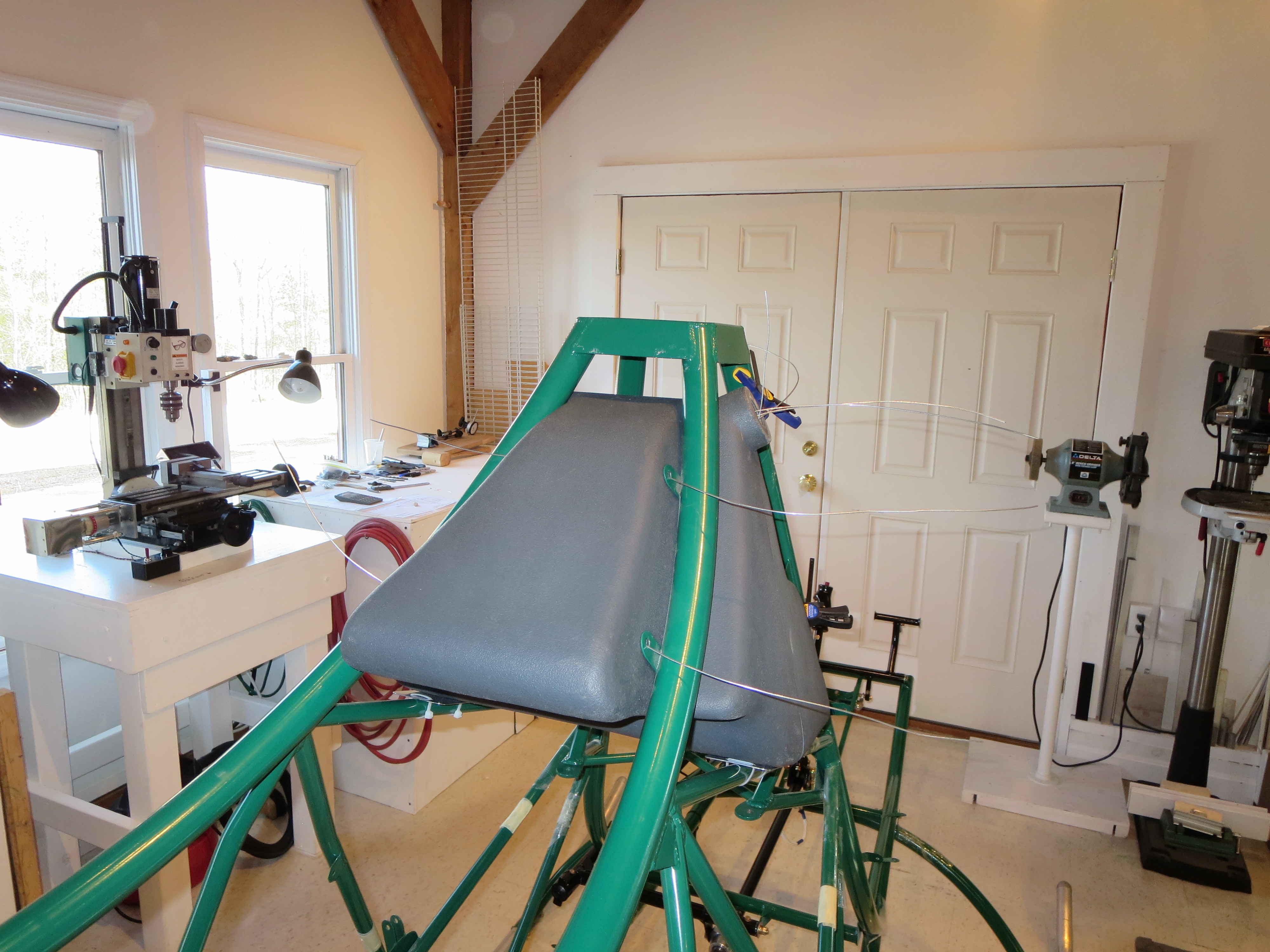
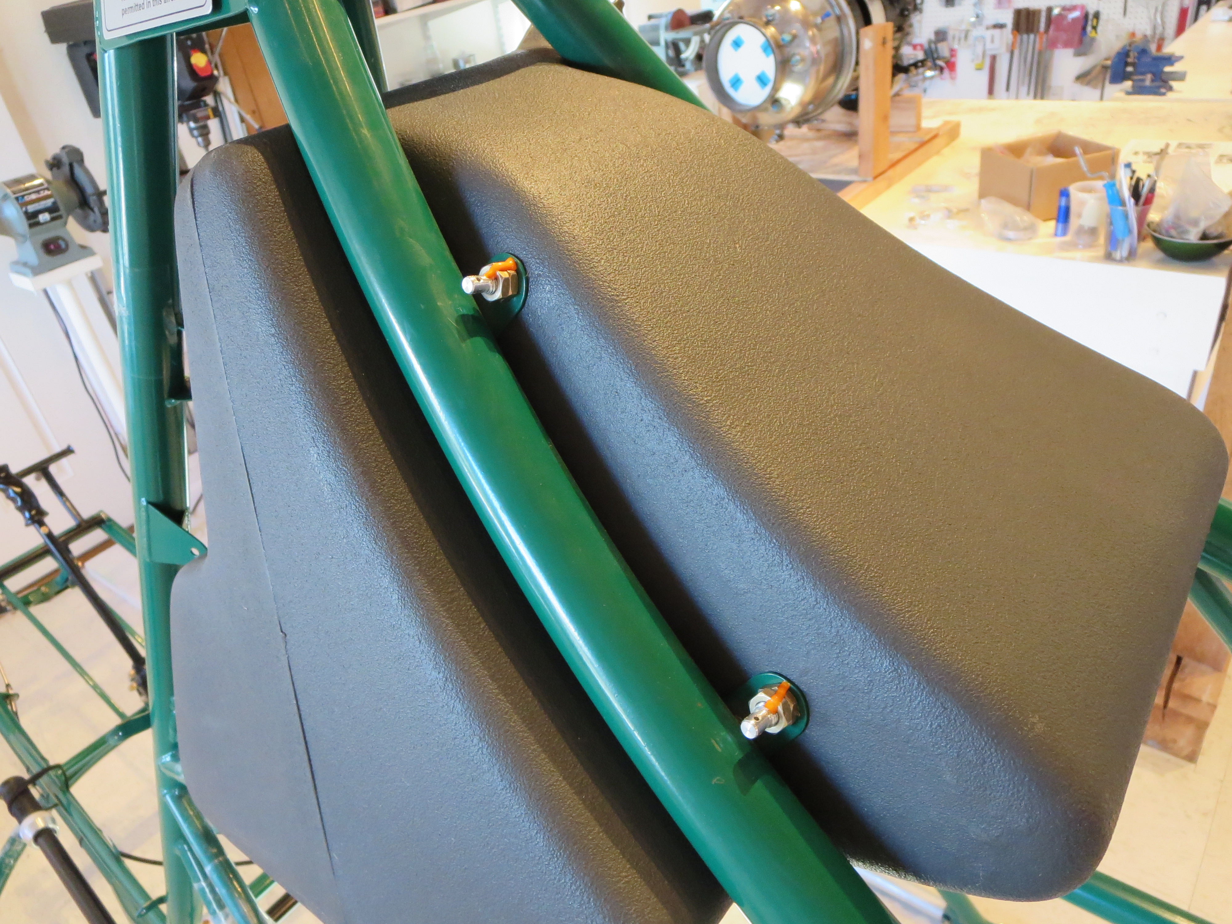
The interior of the cabin will be painted with a Rustoleum "Simply Stone" textured paint. It's kind of like spatter paint from old car trunks. The seat pan top and instrument pod will be satin black for low reflections.
More SP Priming
DISASTER. Right when I was thinking this painting stuff wasn't too hard, this thing turned into a runny, saggy, ugly mess.
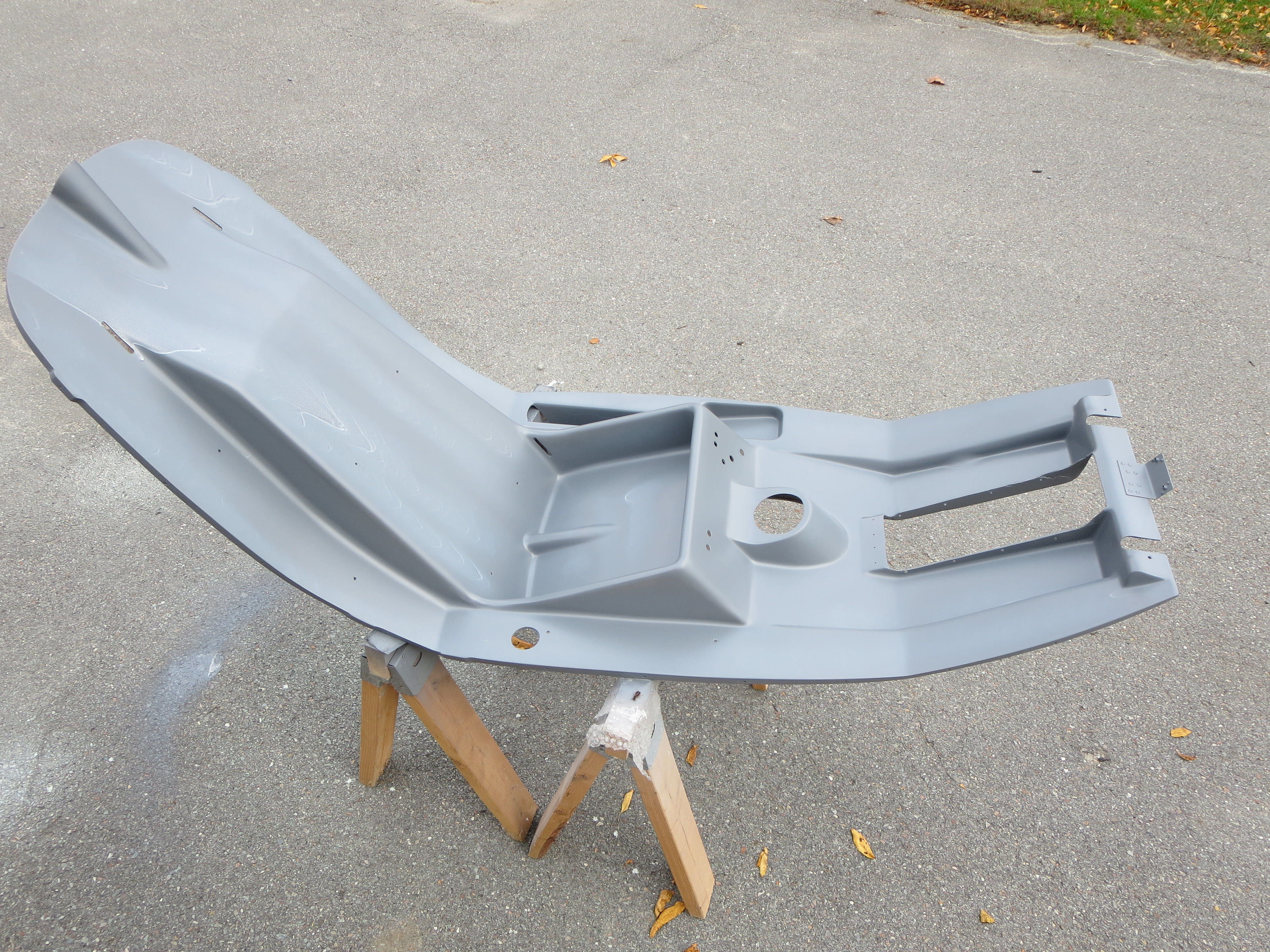
Yuck! You can see the sags, runs, and droops.
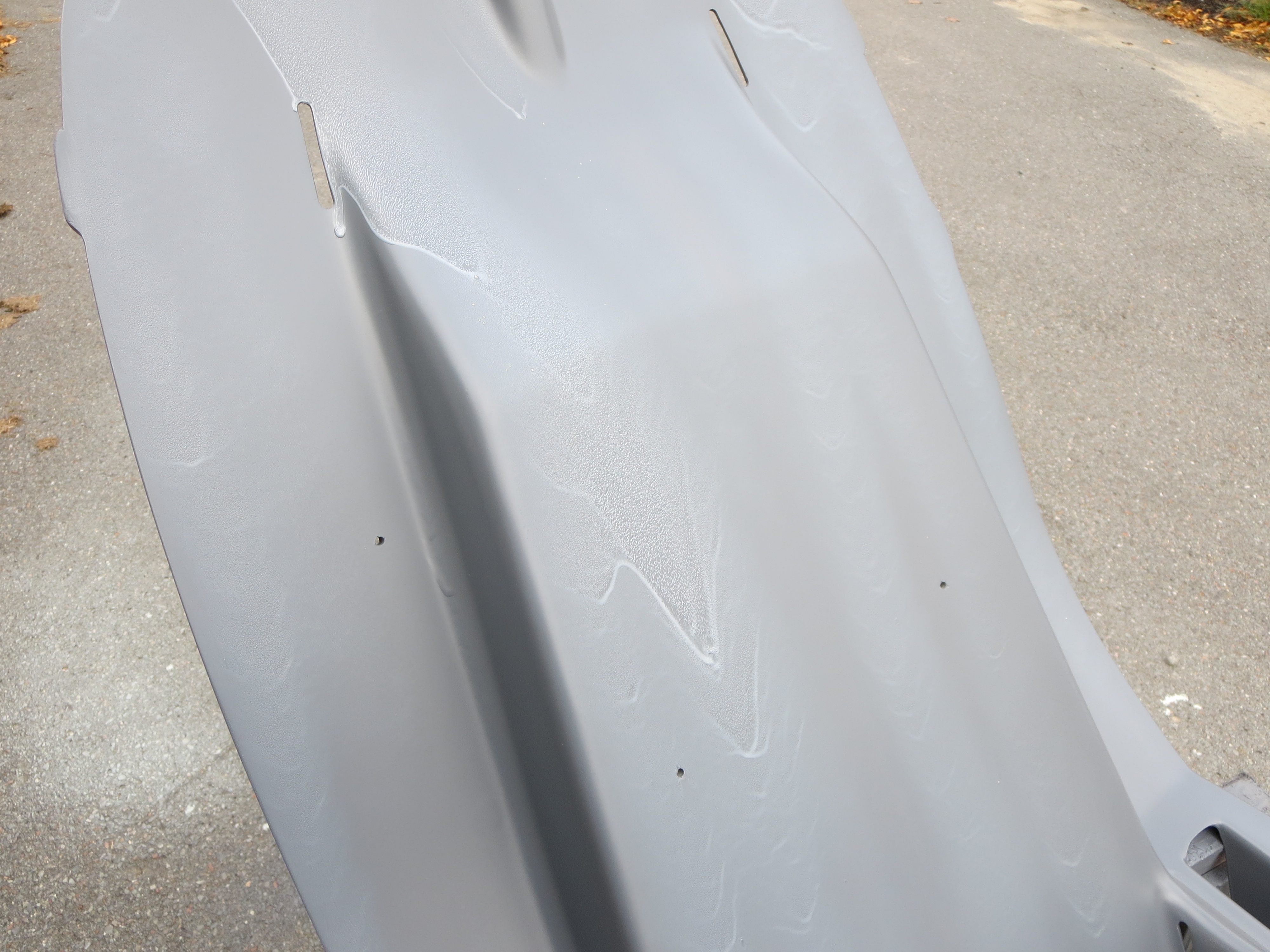
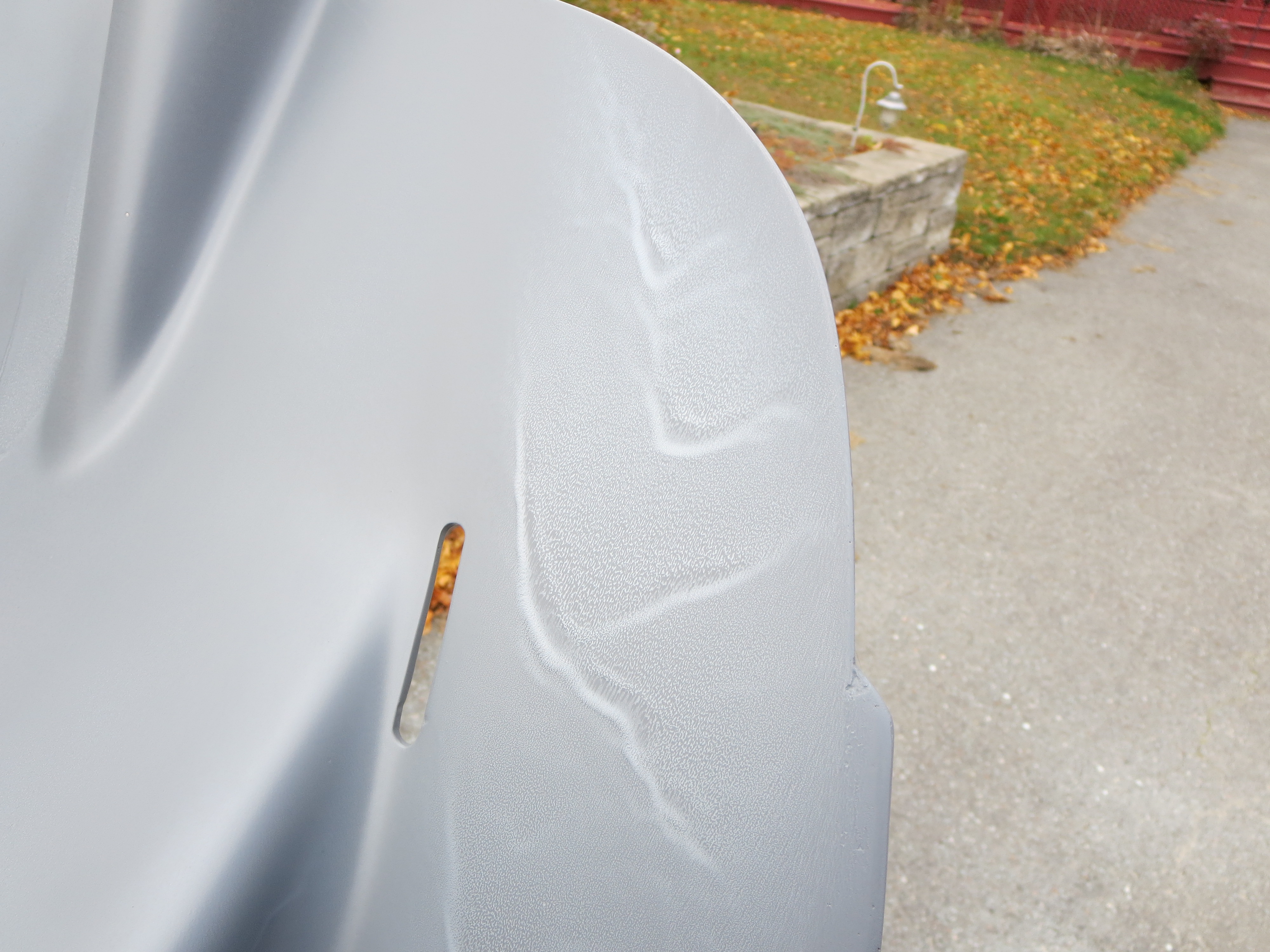
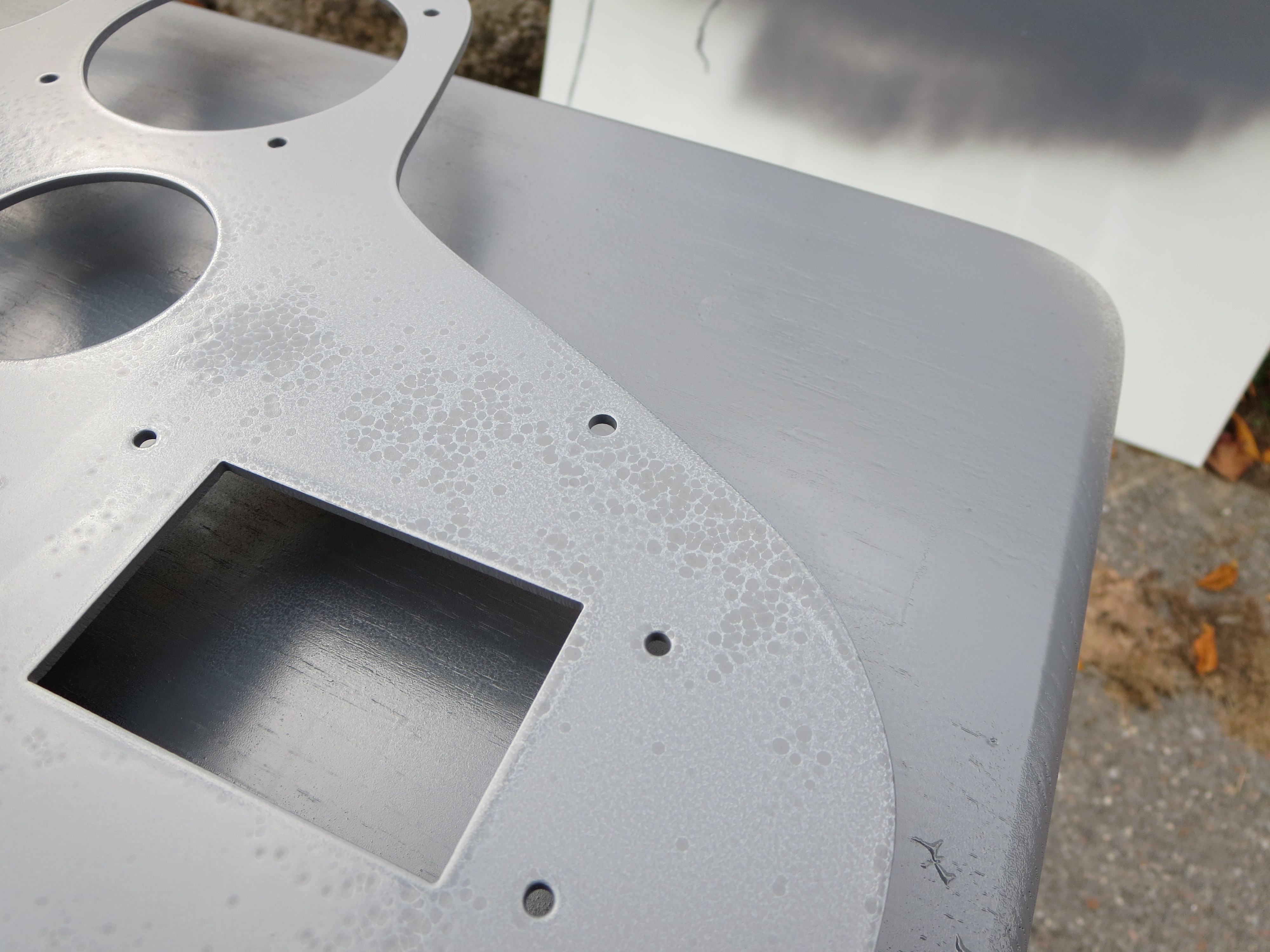
This is the cut panel blank which I primed as well. Those aren't really fisheyes. They are more dimples.
Very rough texture when dry.
Conclusion: Weather, weather, weather. Whereas when I primed the rear of the pan, the day was sunny and dry, the day I did the top side was cloudy and overcast and the humidity was relatively high. It was supposed to rain that afternoon and I wanted to get the primer on before it turned wet. Because of the moisture in the air and the lack of sun I think two things happened. 1) When I did my final wipedown with IPA, it never evaporated all the way. I think that is why the panel has the dimples. There was still residual IPA in the pores of the aluminum. 2) Because of the moisture and lack of sun, the primer did not dry or flash as quickly. The longer to stayed on wet, the more it sagged and ran.
This epoxy primer is tough stuff, so this will be laborious to sand off and start again, but that is the price to pay for getting too cocky about painting. At least it was the only primer. My lesson is learned and I will redouble my attention to conditions.
Lesson learned.
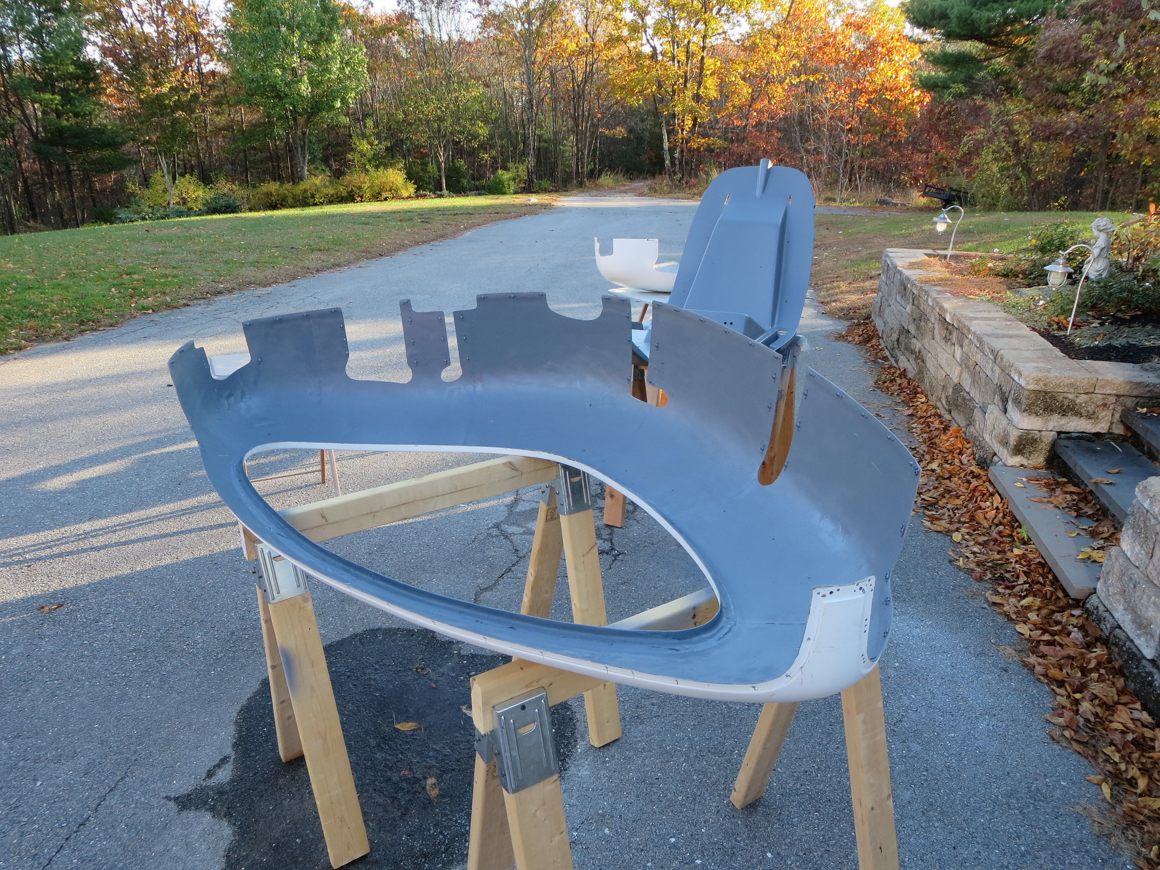
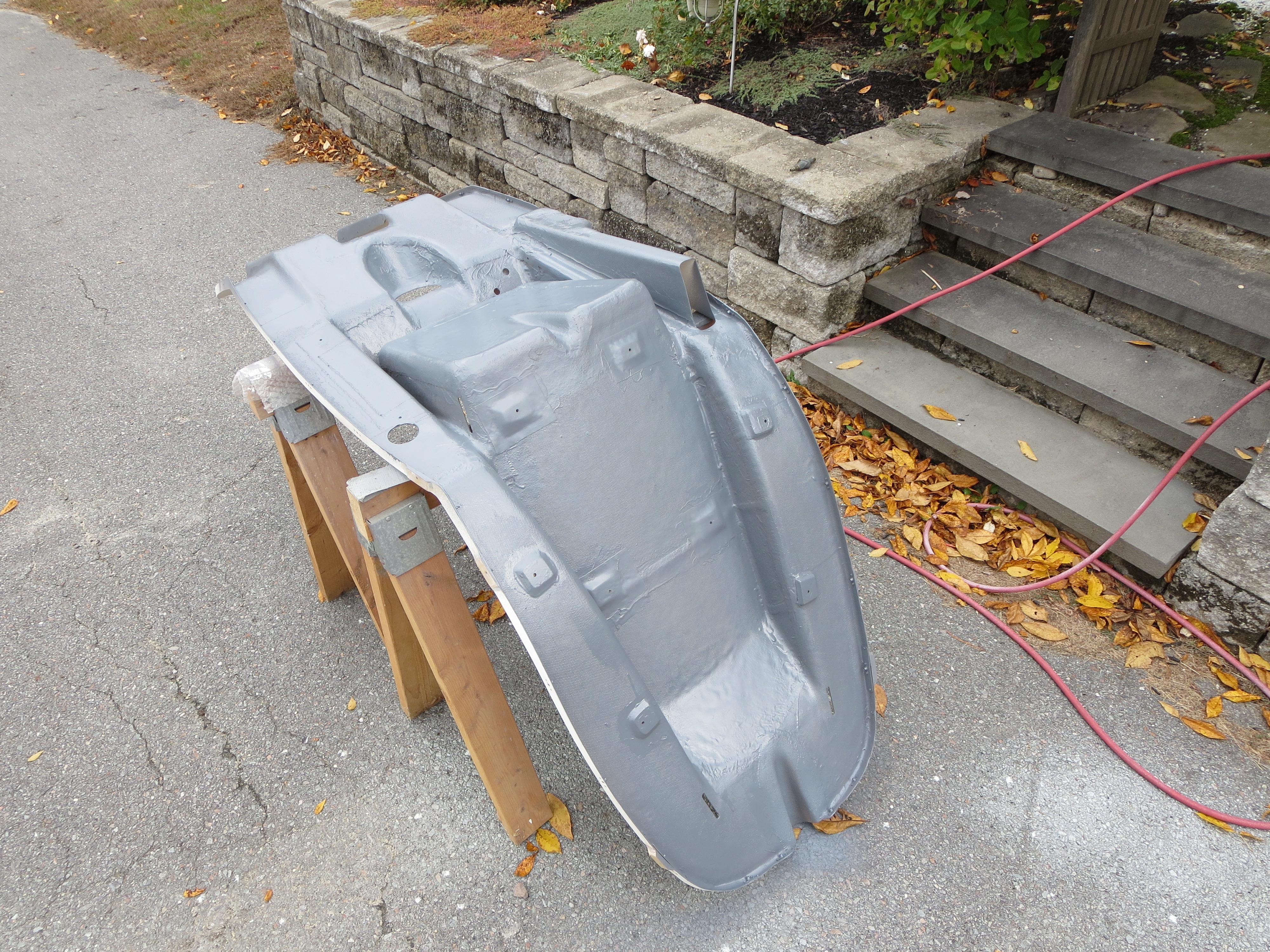
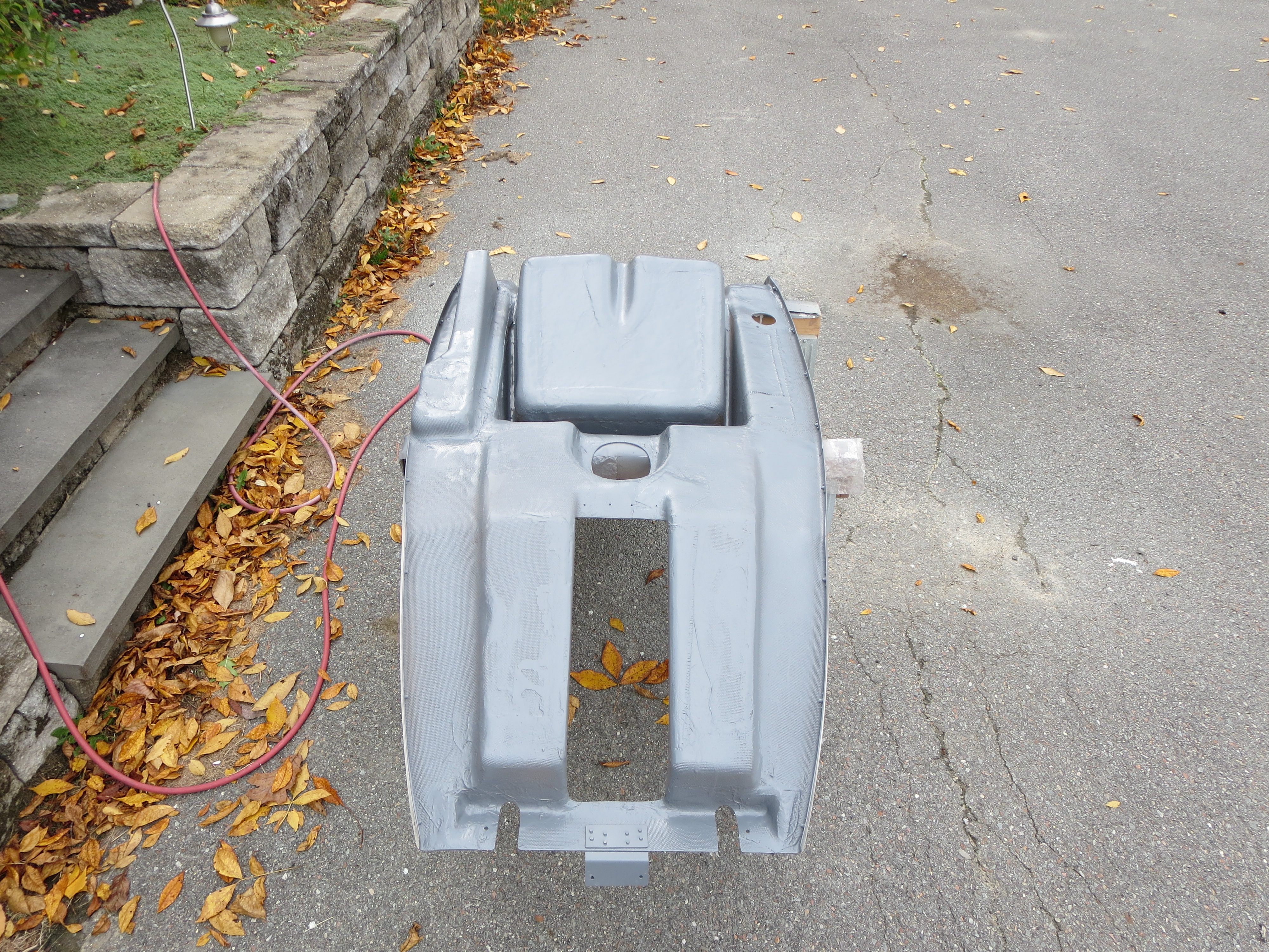
Seat Pan Rear Priming
I broke out my Eastwood 2-part epoxy primer for a quick couple of coats to seal the rear of the pan. This stuff flows nicely and surprisingly almost exactly matches the color of the plastic used on the fuel tanks.
I am not too concerned about the finish on the backside of the pan. This is just a sealer, for the most part.
Reno 2014
I attended the National Air Races in Reno this year (2014). In the display area were two different Helicycles. This was awesome as I have been to a number of Sun-n-Fun and Oshkosh events, and have seen exactly ONE Helicycle at Sun-n-Fun in 2013 only. There were two on display at Reno this year, an official corporate presence, and information on the Helicycle that is being used as a drone. A wonderful showing.
The first machine was Blake’s personal machine from Eagle R&D. This is a basic workmanlike machine that is actually a collection of parts from a number of builds. Here is a slide presentation of Blake’s Factory machine. They may seem like a random collection of photos. They are of whatever was interesting to me at the time.
The second was James Kent’s machine. This thing is a work of art. James has added a number of very advanced enhancements and is finished to a supreme degree. Polished surfaces, chrome plating, and superior craftsmanship really makes an outstanding impression. I didn’t get as many photos of Jame’s machine as I have a whole bunch from Reno a coupe of years ago. Here are a few detail shots of some of the nice touches.
James’ machine was absolutely swamped at the show every time I walked by.
Oil Cooler Endcaps
Here are the end caps to the Hap Miller supplied oil cooler. This labeling is not strictly necessary, but a start.
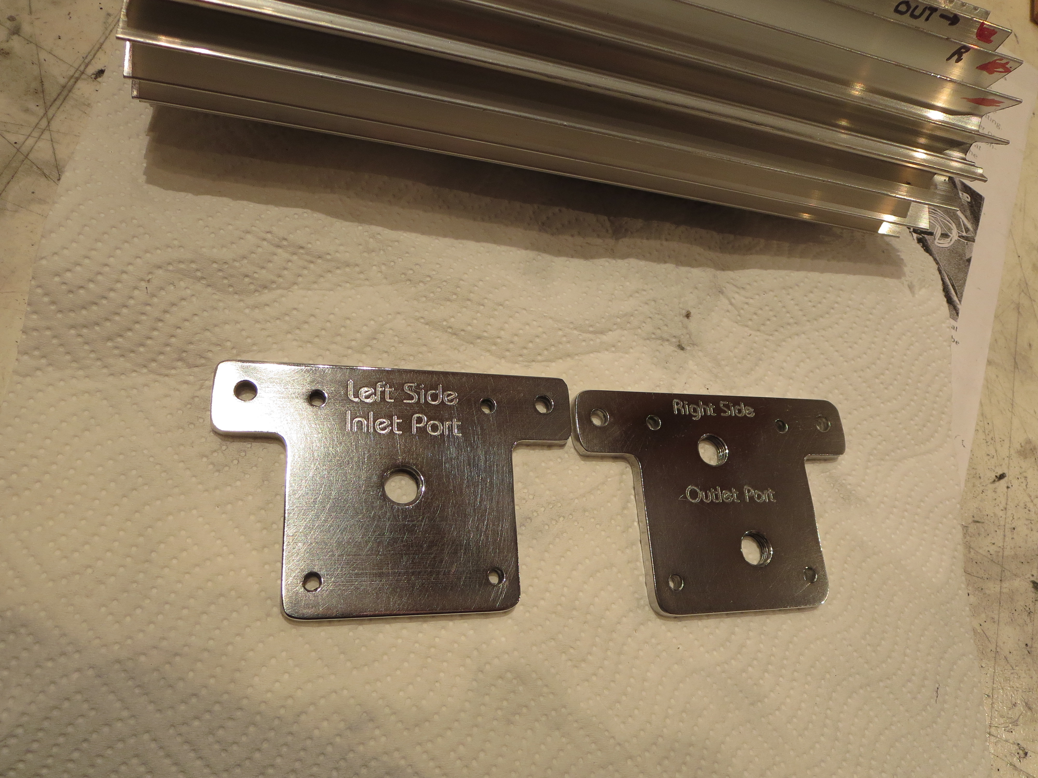
That's just a quick "shop polish". A camera angle that highlights the engraving also highlights the unpolished scratches in the aluminum. I am thinking I will just leave the oil cooler extrusion "natural clear anodized" and the end caps polished (more than this, though).
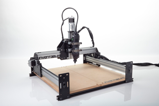
Shapeoko 2 CNC Router
For my birthday I got a Shapeoko CNC router. Shown is the basic stock configuration. I only purchased the mechanical kit (no motors or electronics). The first thing to do was assemble it as shown and then evaluate where it was strong and weak prior to modifications.
My goal with the machine is to be able to fabricate complex brackets out of (up to ) 1/4" Al plate. I thought about a real CNC mill, but was not willing to invest the time or cash at this point for a big machine. Turns out that was probably a good idea. This is a neat machine, but it may fall short of my goal. Still, it is a great way to learn CNC without a massive investment and to figure out a tool flow and develop experience that would be far more expensive to do with a bigger machine. I will ultimately end up probably with a CNC version of the Grizzly G0704, but that is a longer term thing.
Here is my own modified end product:
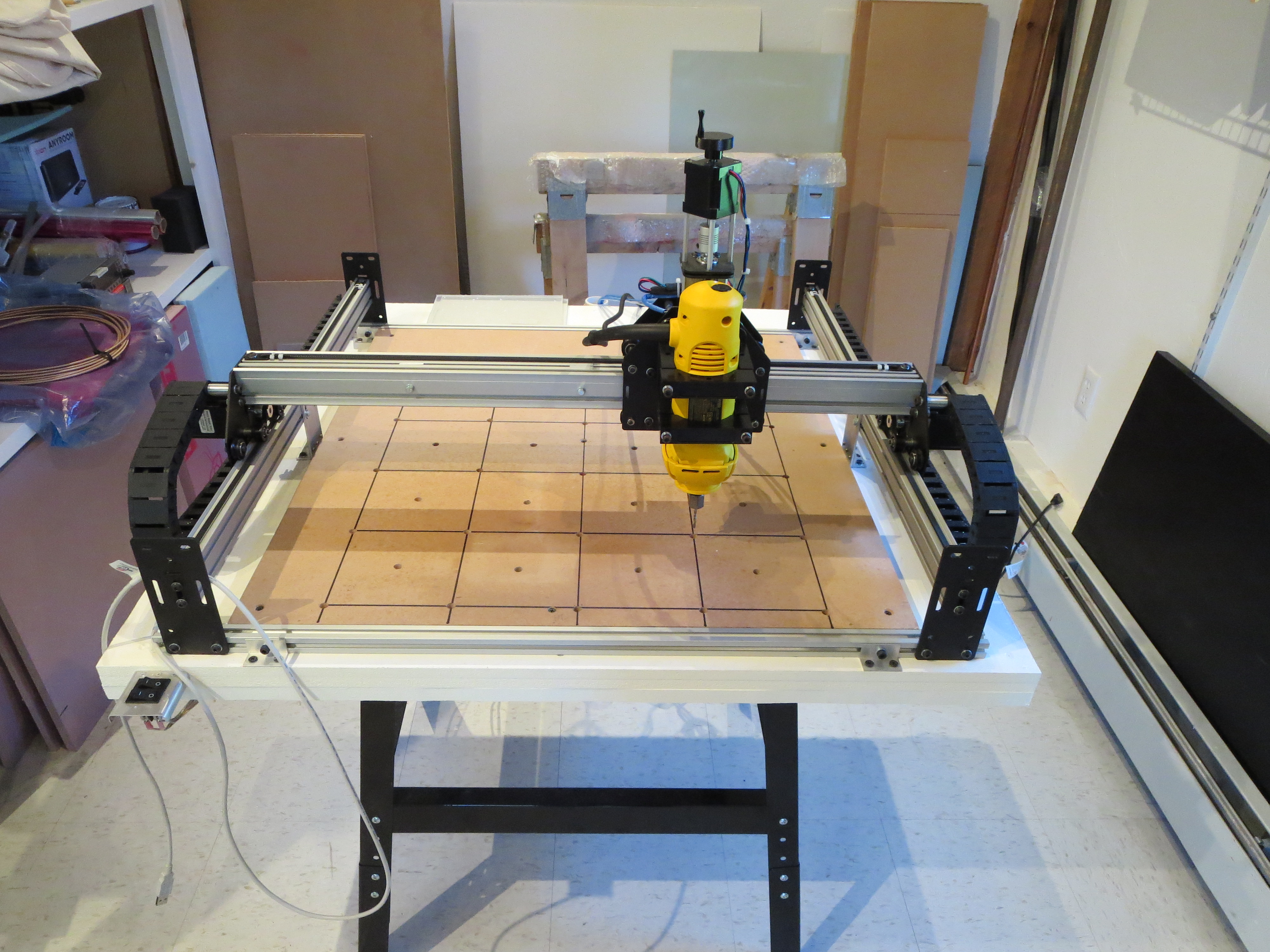
Modifications include:
1) Longer X and Y travel by 50% (up to 750mm from 500mm) doubling work surface area
2) Stiffening Y travel with mid-span brackets
3) Stiffening X by bracing dual extrusions together. Reduces torsional twist.
4) NEMA 24 motor upgrades on X and Y axes
6) Dewalt DW660 router for cutting. This thing is a beast. Very, very loud, though.
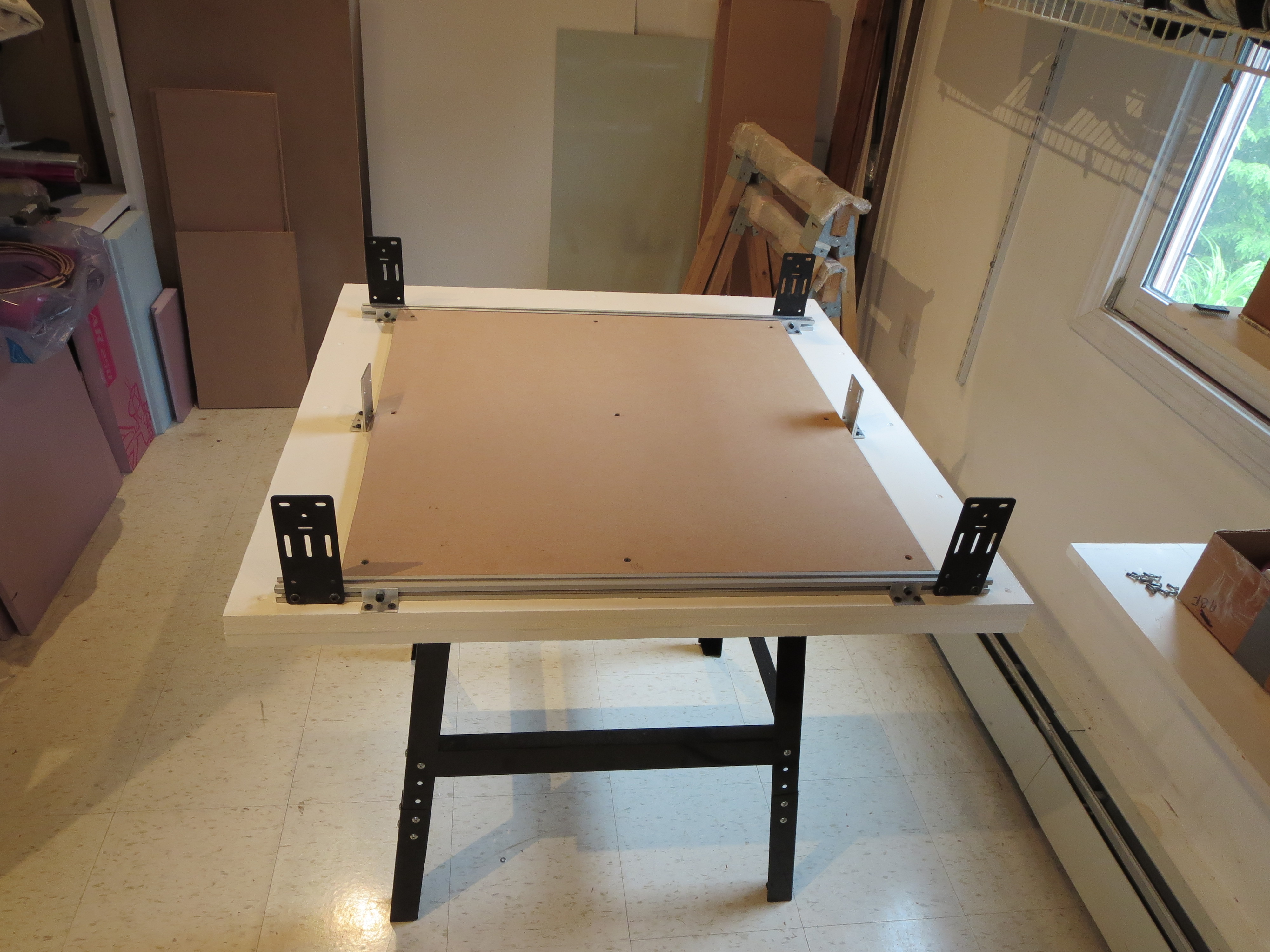
The table is a Harbor Freight $29 tool table. I buy less and less stuff from HF because of their marginal quality, but sometime they have just the thing. The base is layered MDF up to 1.75" think. The sheets are screwed and glued, but prior to that I shimmed them the best I could for flatness. The wasteboard is 0.75" thick.
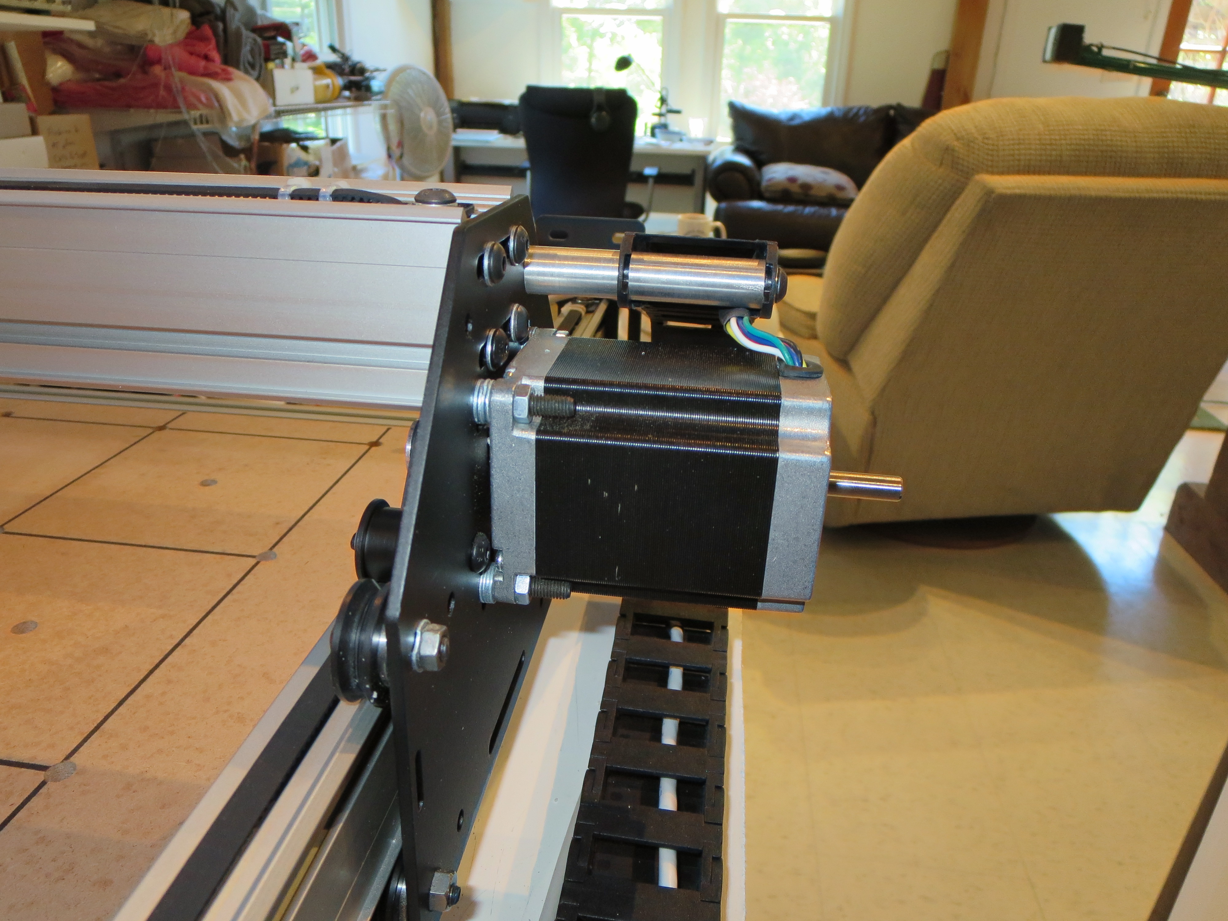
The Y-axis motors are NEMA 24 upgrades. a little shimming and careful attention to build order in order to fit it all together. Some quick lathed mounts for the drag chain.
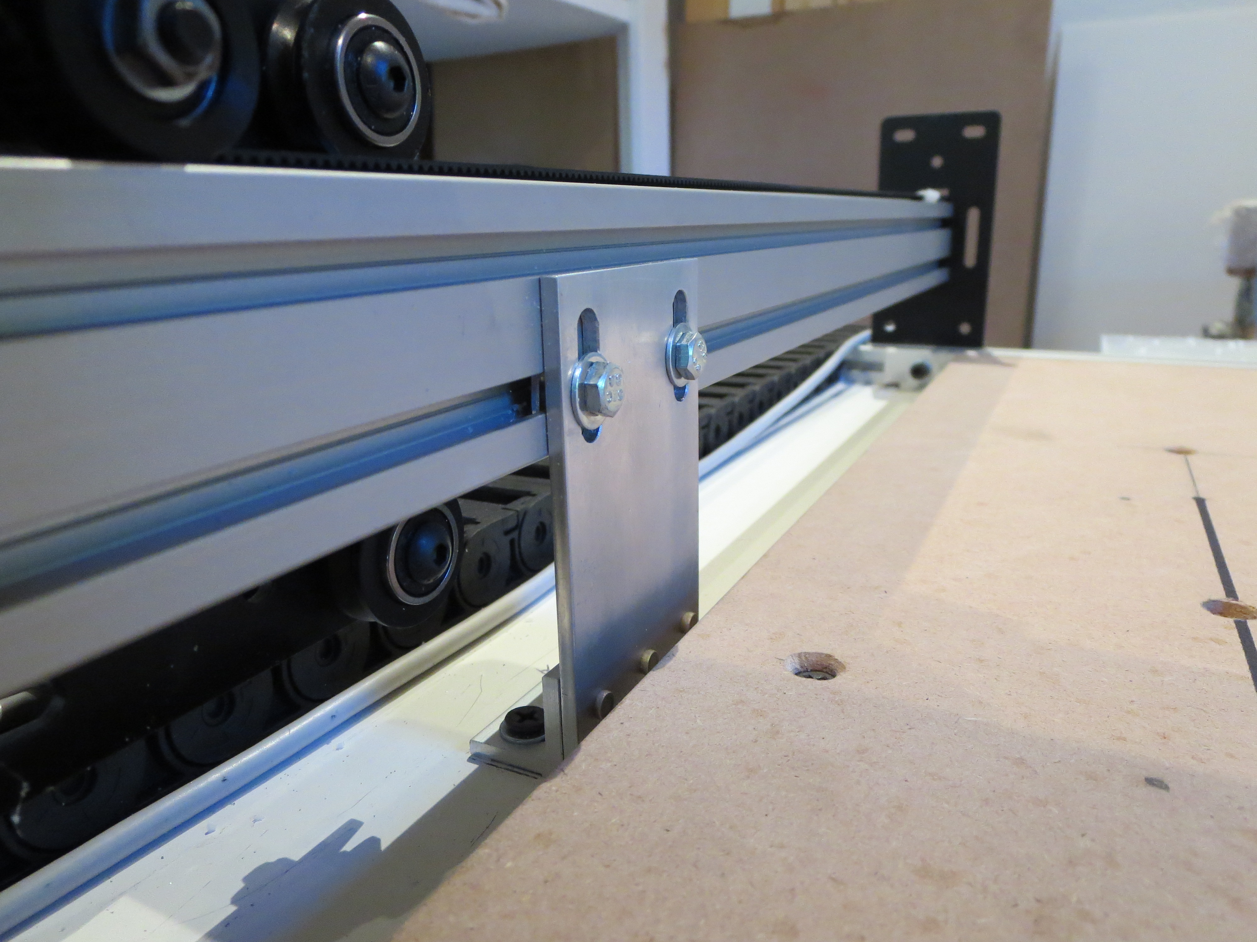 Whipped up a couple of braces for Y-axis support. Simple angle and plate machined up on my mill. Riveted with aircraft project leftovers. Nice to have the tools and materials at hand. The longer Y-Axis needs support in the middle and this also keeps the fore and aft direction from flexing.
 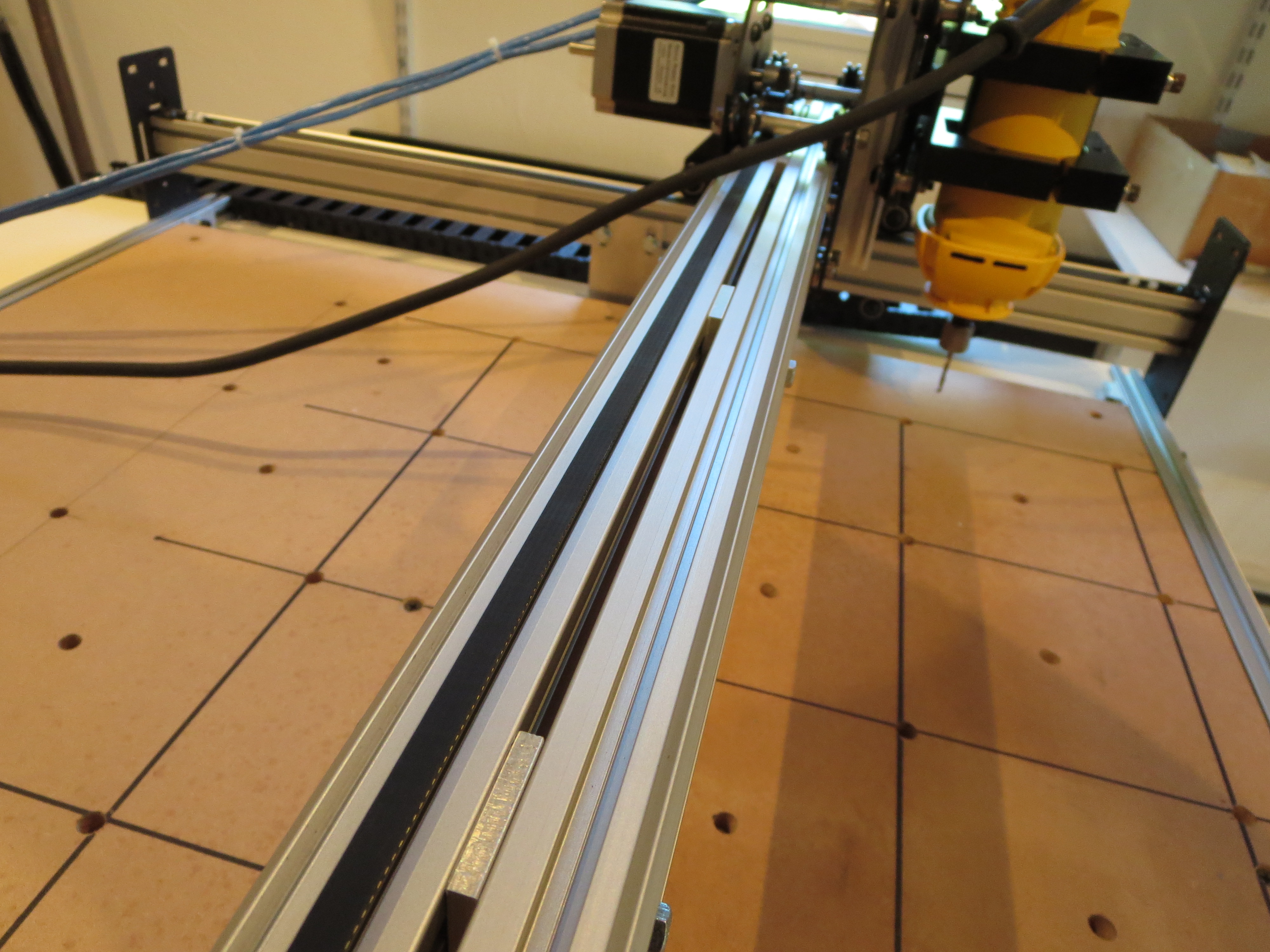 The stock configuration only has the pair of extrusions only attached at the ends. To keep the extrusions from flexing relative to each other, I first built up the carriage, fitted it, and measured and fabricated proper thickness shims to affix them together. This really stiffened up the carriage in the vertical dimension.
It is important to build it up before measuring for the shims as the width can't be determined accurately until the thing is fit together to find the "natural" width of the carriage rollers.
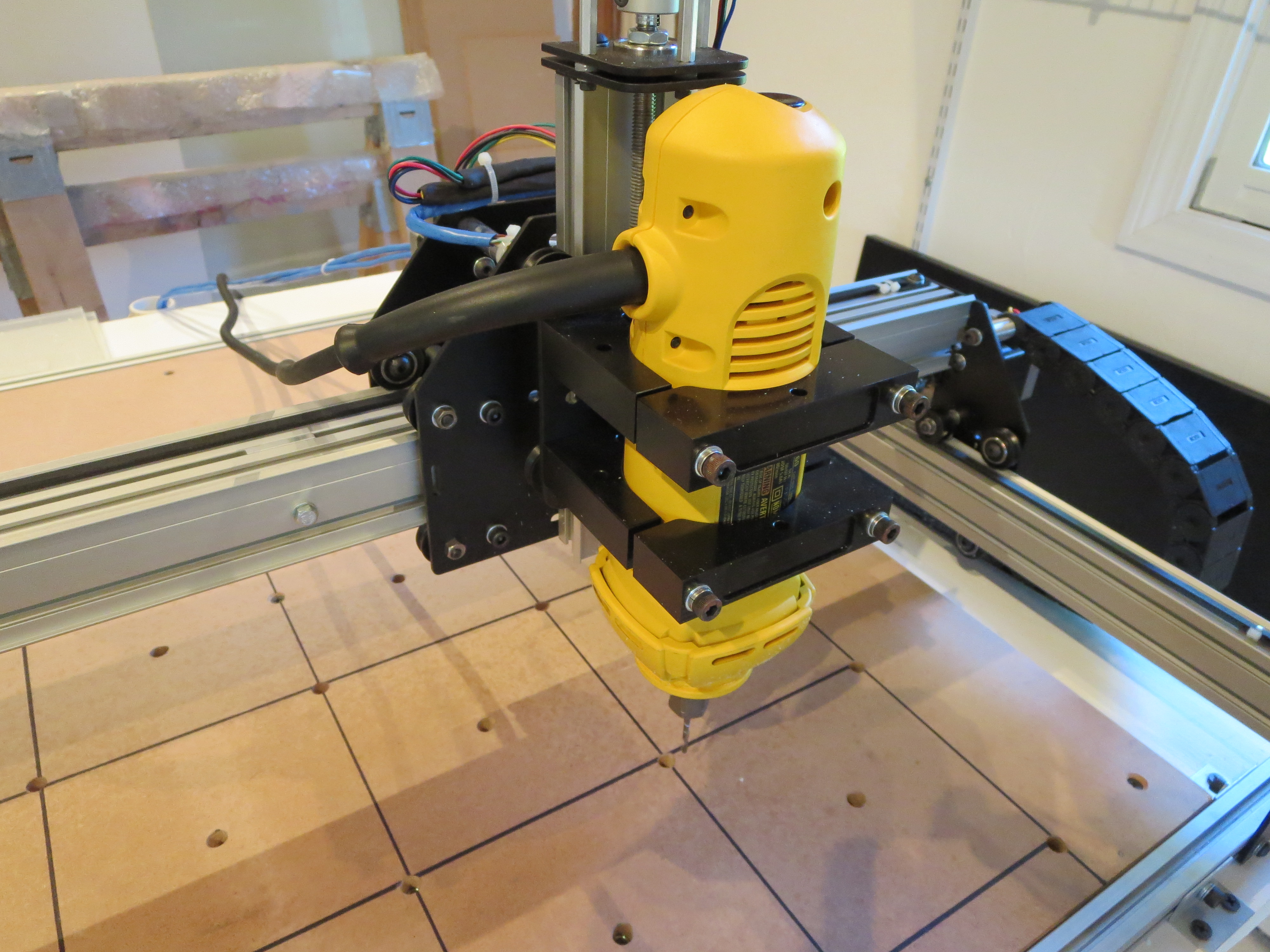
The DW660 router is much heavier than the stock spindle and needs good bracing. The wires from the X-axis and router will be dressed better when I get a smaller drag chain. Works for now.
Electronics bolted to MDF plate in the back of the machine. Protected by the table top, so I didn't feel the need to make a full case.
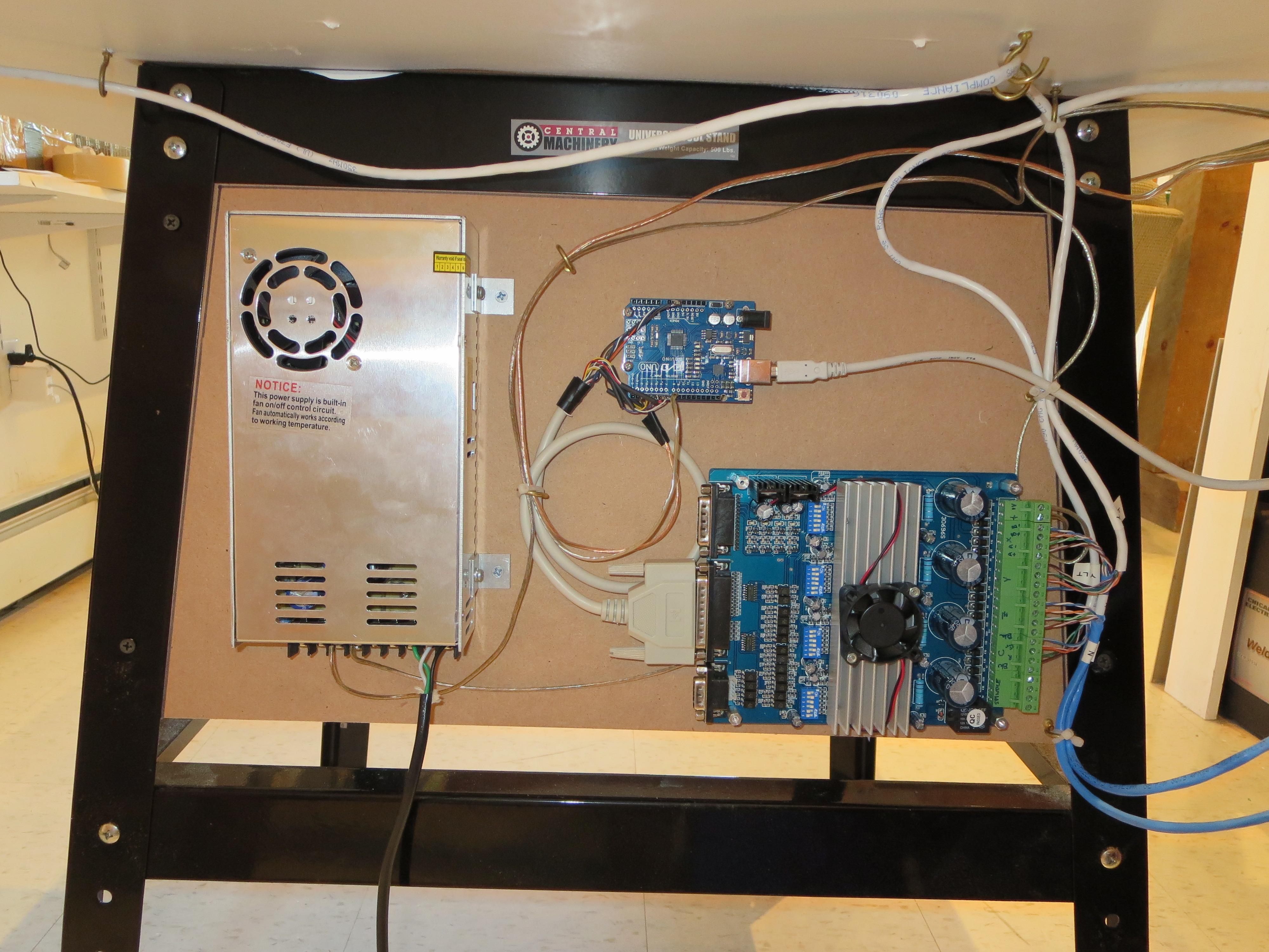
The motors and controller were purchased off ebay for about $200 from wantaimotor.com. Wow. Lots of capability for short money. It all worked, but was not at ALL documented and the limited docs that were provided were WRONG. A lot of web searching and reverse engineering needed to figure out pinouts, voltage levels, and controls. The controller is an Arduio UNO ($10 on ebay) running GRBL. Doesn't get much cheaper for CNC control.
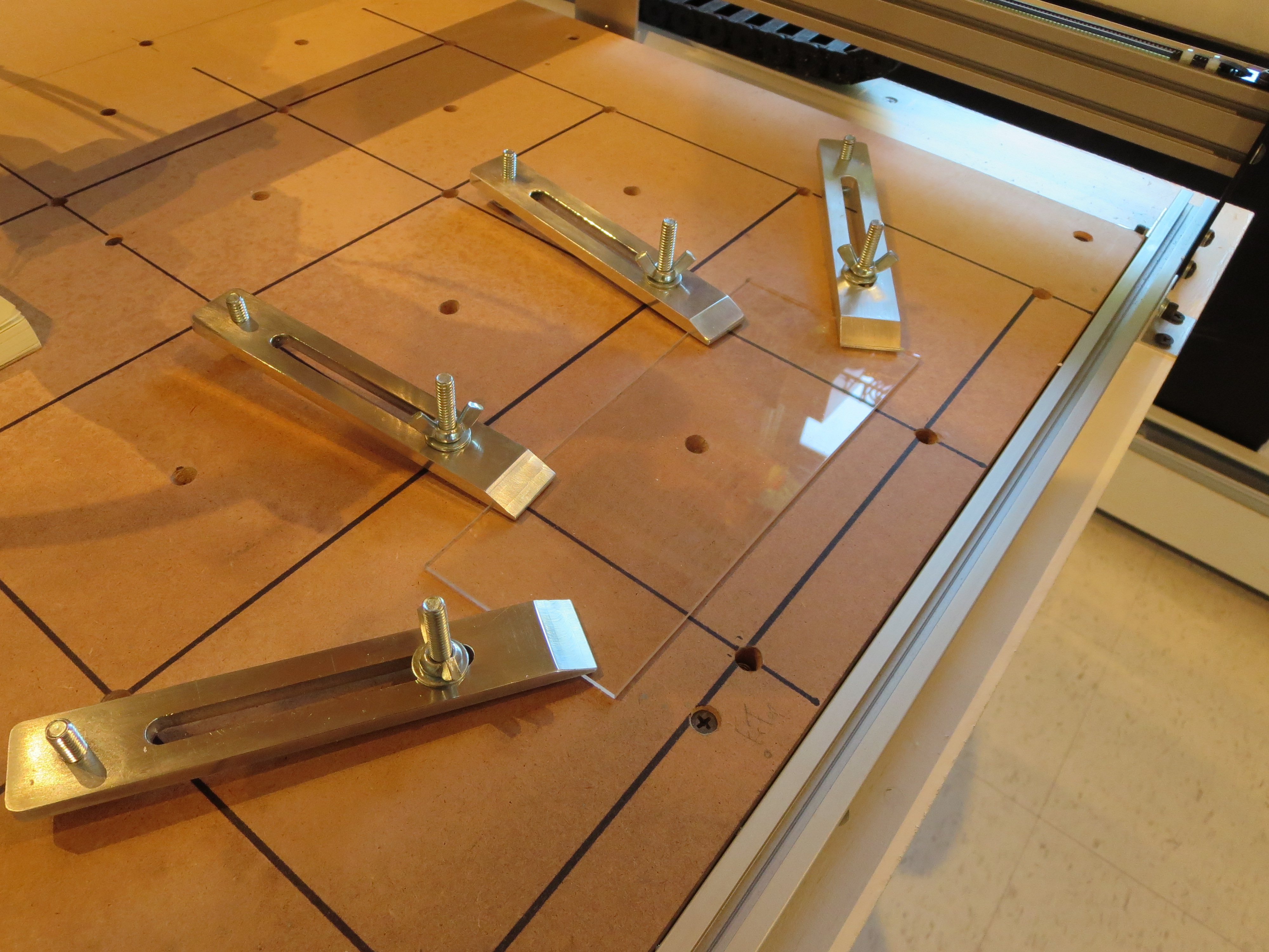 Made some hold-down brackets on the mill. The washboard has an array of T-Nuts installed flush from the bottom. Screw the threaded rod from the top into the wastboard, slip over the hold-down, adjust the carriage bolts for the right angle, and then spin the wing nuts to tighten. Simple and effective.
My tool flow is:
Spaceclaim (running under Windows VM on my MAC) - 3D and 2D modeling of parts and brackets. Export is DXF (2D) or STL (3D)
or
Adobe Illustrator (running OS-X on MAC ) for art drawings and 2-D text for engraving. Export is DXF
CAMBAM (running on Windows-VM on MAC)for tool path generation. http://www.cambam.info
Universal G-Code sender (running OS-X on MAC) for controlling the machine (free)
So all-in I had to buy CAMBAM for about $180. The rest was free or something I had already.
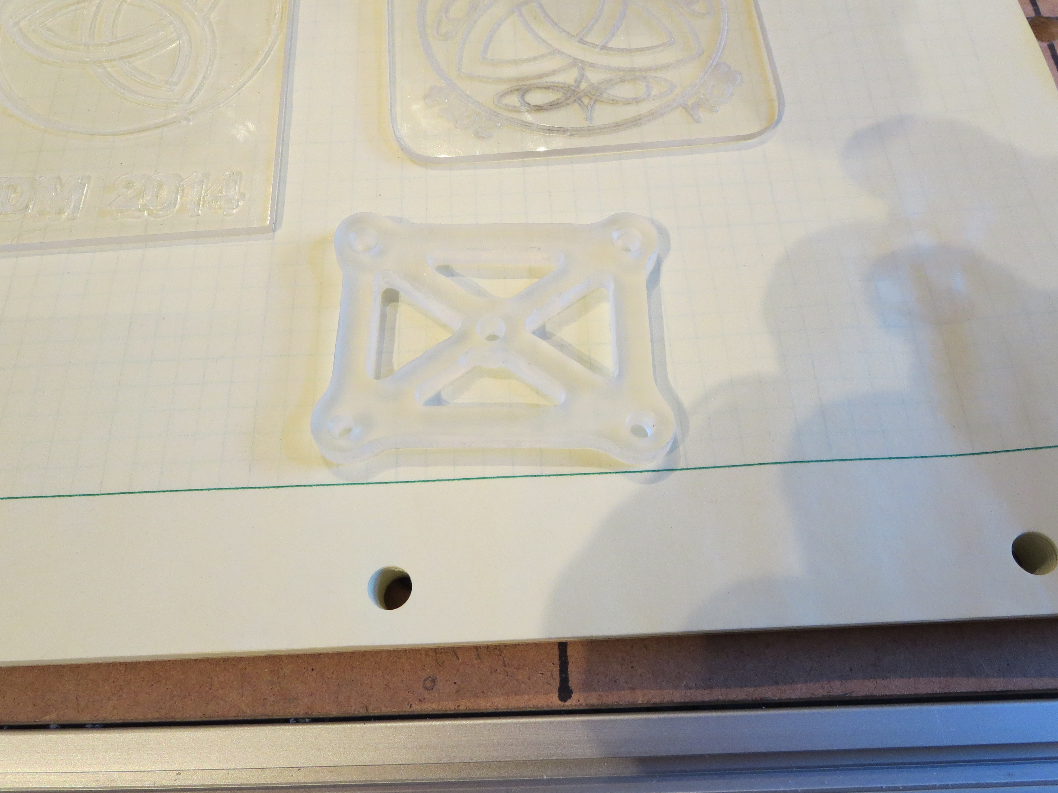
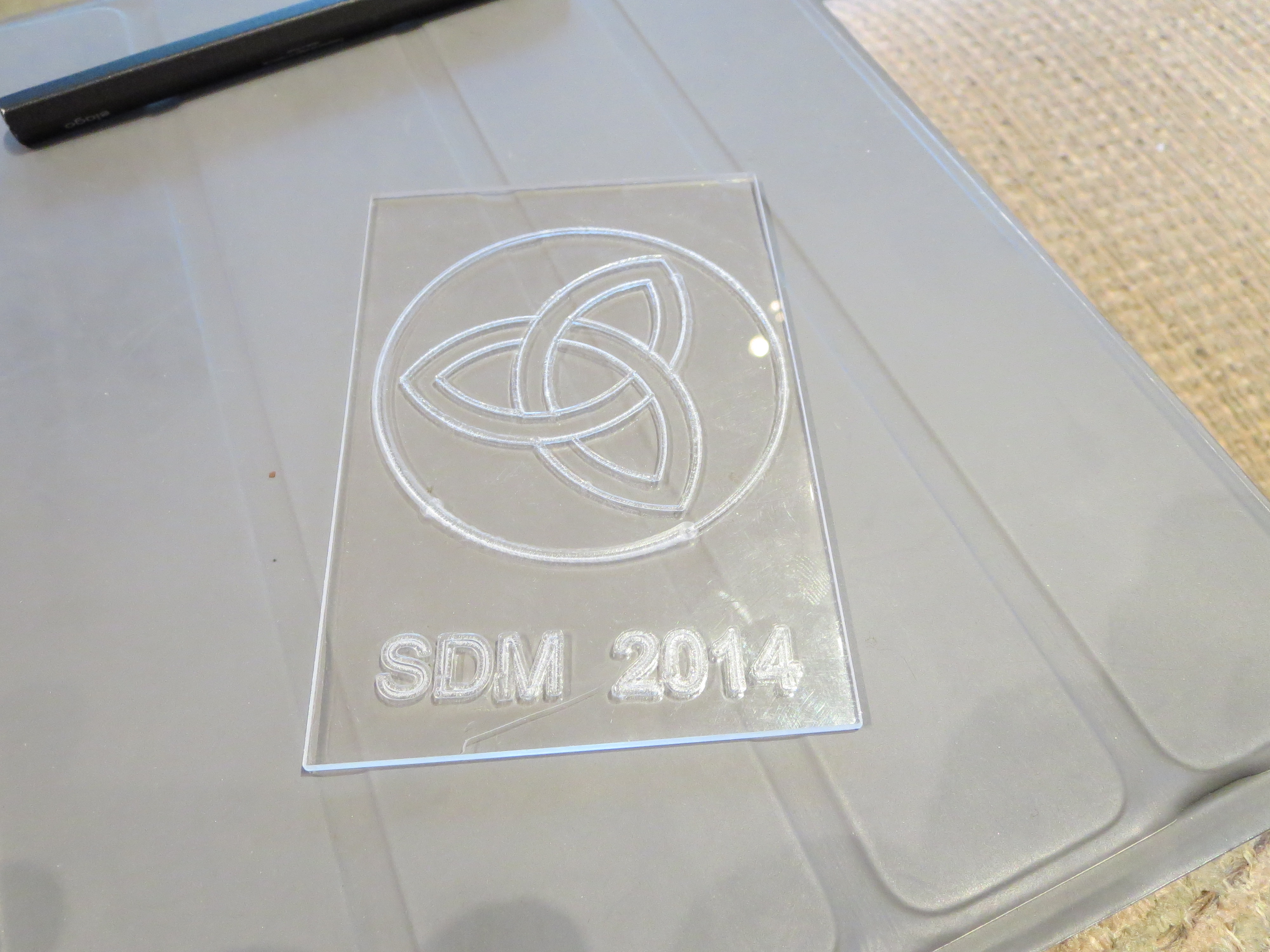
Here are some early examples in some plexi scraps I had lying around. Obviously I have to work on tooling and feeds for better results. Cutting plexi is weird in that you have to be careful. If you cut too fast it "fragments" at the cutter. Too slowly and the plexi melts and build up on the cutter, affecting the accuracy of the line.
Conclusions:
For engraving this will be great. For milling soft stuff it's probably fine - haven't done much there yet. For aluminum it is weak. It is just not stiff or strong enough, even with my modifications, to accurately cut thicker plate. I will experiment with speeds and tooling to see if something acceptable can be determined.
The machine works great for what it is. I can see perhaps cutting outlines and lightening hold in brackets, then moving the piece to the mill for accurate cutting of holes. It is very satisfying to see it run repeatably and position accurately; hypnotic almost. I have learned a lot and when I do get to the construction of a man-sized mill it will go much more smoothly. I have purchased a 2W laser from ebay to try my hand at laser etching. That'll add a whole new level of danger to the shop.
My total investment is about $700 and a month and a half of weekend spare time. I think of it as a self-taught course in CNC machining. From that perspective it seems pretty cost effective. It's now just another tool in the shop. Like the Mill - it was a project that once done will become a very useful tool. Time to get back to the Helicycle.
Main Shaft Plug

Well ahead of the transmission installation video in the rotor head video, BJ mentions how the main shaft should be plugged to keep out moisture. First up was to slather a goodly amount of Corrosion-X in the shaft after a few acetone swipes. Then I lathed up an ABS plug that was snug, but not even really "tap tight". Once parted the plug is only about an inch long.
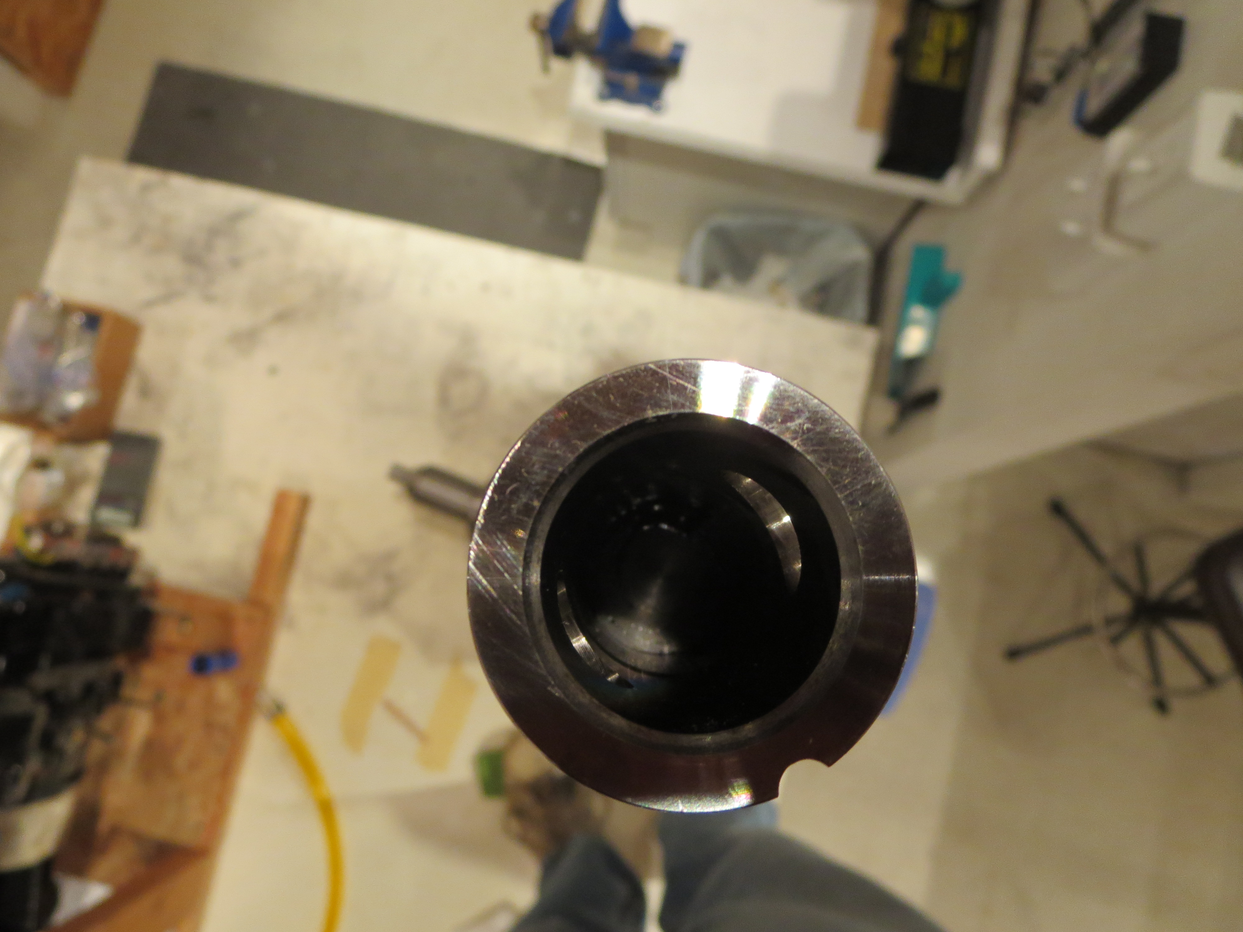
The plug was coated with 5-minute epoxy and slid down inside the tube. I measured the steel main drive plug that slides inside the shaft, then I pushed the moisture plug down plenty far enough to clear the plug when it is installed. While the epoxy was setting up I wiped and cleansed the inside of the tube above the plug with acetone to remove any trace of the epoxy so the drive plug will not be fouled when it is inserted.
The edges of the hole for the drive pin are sharp, sharp, sharp, and I cut the hell out of my finger while swabbing out epoxy. Nice mixture of acetone and epoxy now coursing through my bloodstream. About every two weeks I will cut a finger, grind myself or otherwise accumulate minor scar tissue on this project.
Lower Tank Closeup
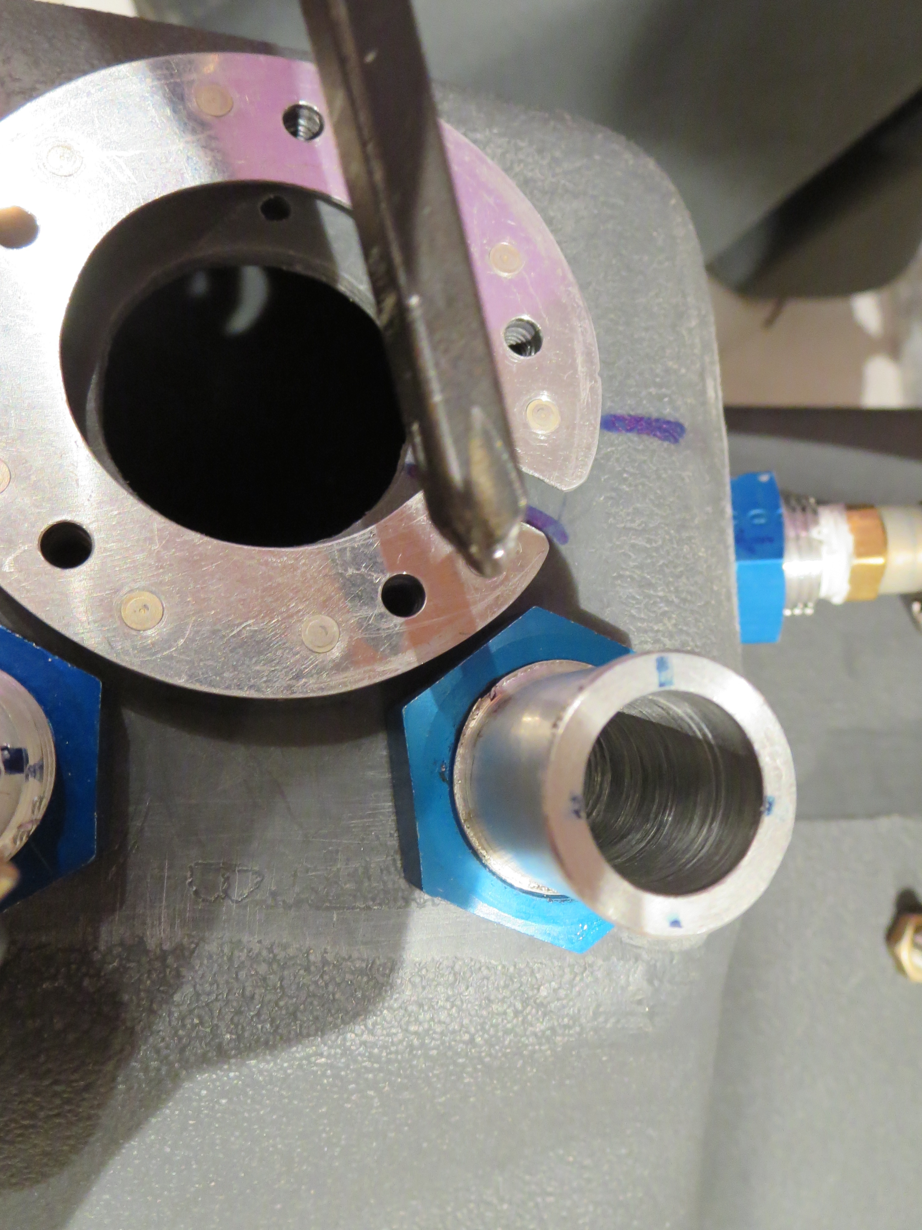
I dried out the lower tanks and closed up the access hatches. Of course I discovered that there was an interference between the retention ring then the inner part of the nipple fitting inside the tank on the left side where things are pretty tight. Fishing the ring in the tank without dropping it is bad enough, but then fishing it back out is a double pain.

Once sealed, the tanks were pressurized with an extremely sophisticated, NASA inspired pneumatic pressure source. Then all the joints and interfaces were brushed with soapy water to check for bubbles. No bubbles.
With this last set of tasks on the lower tanks, they are ready to install. They can't be final installed, though, until the main transmission is installed. That is now the focus. It has already been fitted once and aligned, so all that's left is to reinstall the plumbing and some final surface prep with Evershield.
Surprisingly those balloons were pretty good. They stayed inflated for 6 days with only the slightest shrinkage. Usually party balloons self-deflate after a day or two.
Rebalancing the Pulley
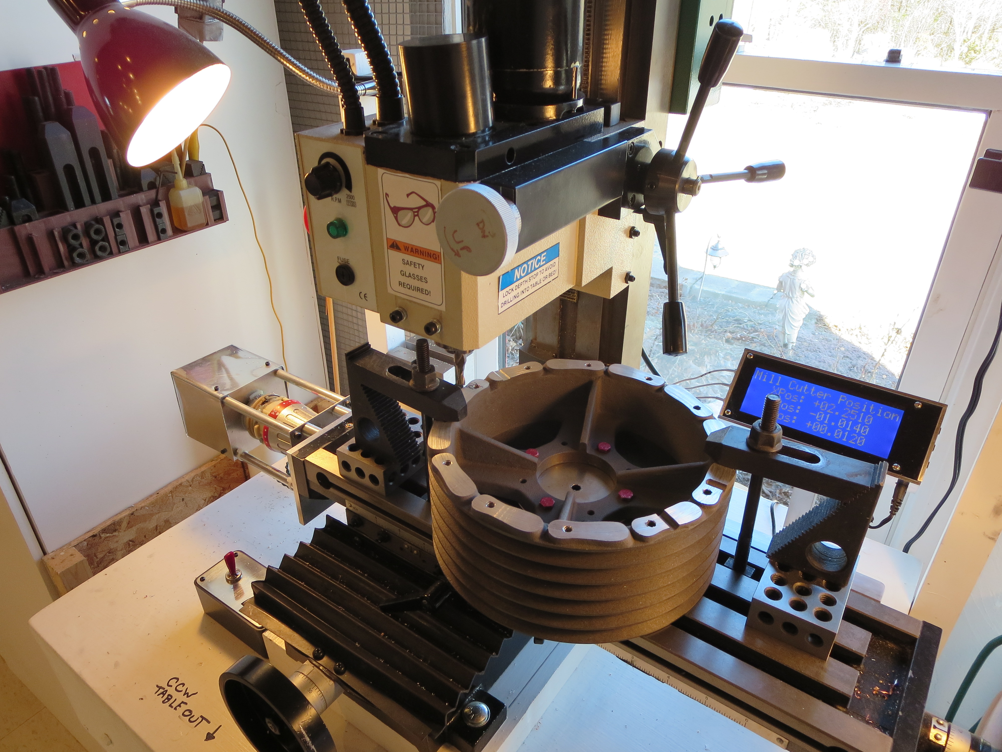
The locations that needed milling were on the side opposite the holes that had been drilled. This kind of makes sense if the holes were drilled to compensate for differences in the mass of the bosses that were milled off.
Lower Tank Final Prep
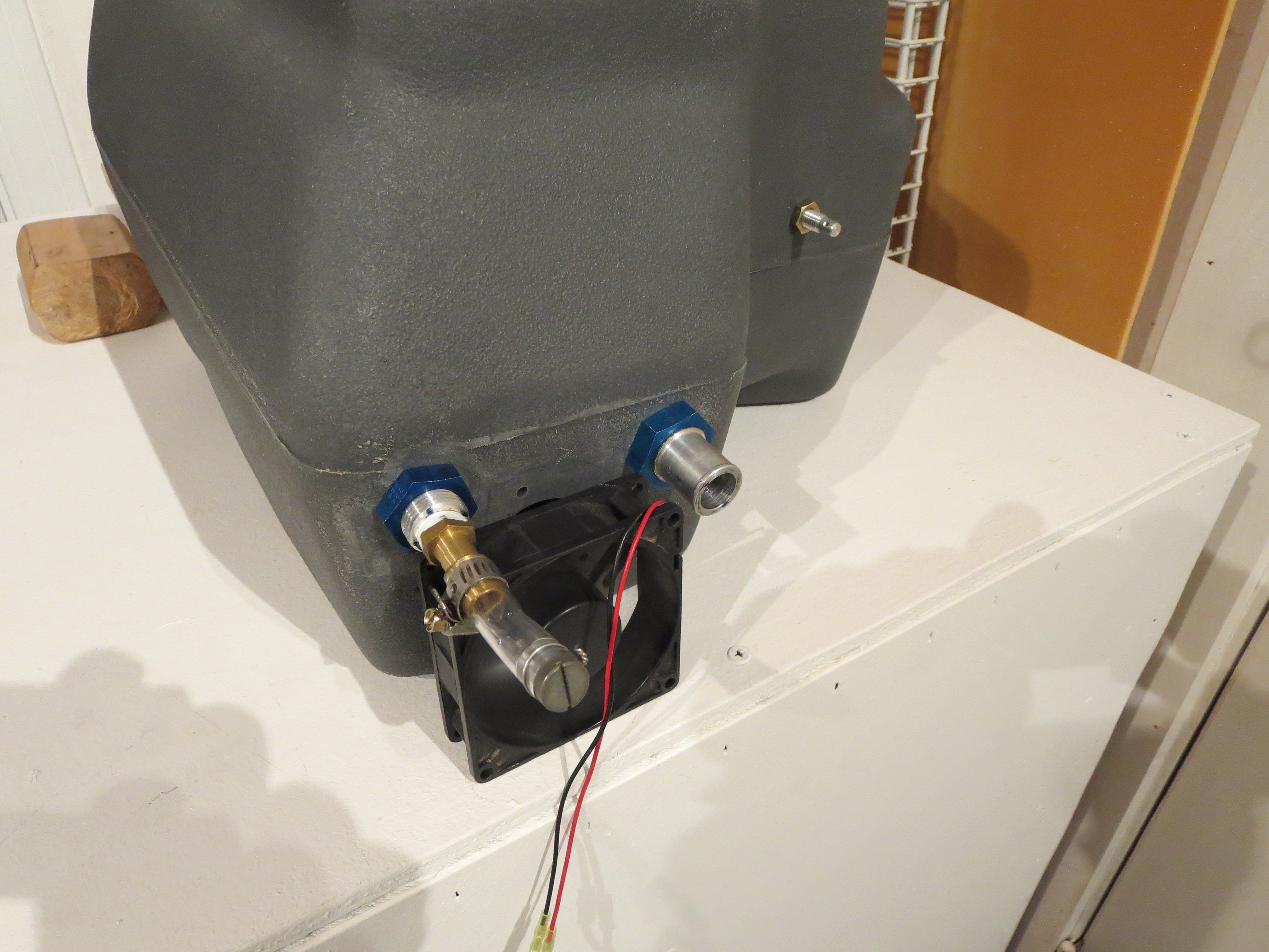
I blew all the crap out of the lower tanks and gave them a good rinse. I did not want to do the final rinse with gasoline as BJ suggests since all my work is inside my shop and it would get stunk up. That left the problem of drying them out after a rinse. Turns out that a little muffin fan blowing in the large hole and venting out through the upper hose nipple was enough airflow that after a couple of hours they were bone dry inside. Excellent. Next up a pressure test.
Transmission Final Prep
Now I have to dig out my references on how to re-install the plumbing.

Since I am not planning on installing the fiberglass fan blades the bosses cast onto the pulley are just dead weight, so I chucked up the main pulley in my lathe and shaved them down. Any extra room in the pulley bay will be welcome I am sure. I left a little meat on the pads from the bosses to give me something to mill off in case there is some balancing to be done. You can see the remains of a couple of leftover holes that must have been drilled for balancing purposes back at the factory. I will admit that I did not notice those balancing holes until I started cutting and now will have to rig some sort of jig to allow for redoing the balance.
This is the largest thing I have ever worked with in my lathe and it was clearly operating at capacity.
Top Tank Final Mount
Double nuts, Loctite, and Torque Seal.
Clutch Final Assembled
I used the Hap Miller compression disk instead of the stock rubber biscuit. Looks nicer and should be more stable. The bolts holding the angle plates are only bolted through the tubes, so the bolts can't really be torqued to spec (60 in-lb) without deforming the tubes, so torque was lowered a bit. All bolts were Loctited and all sliding surfaces were greased prior to final assembly.
Controls Installed

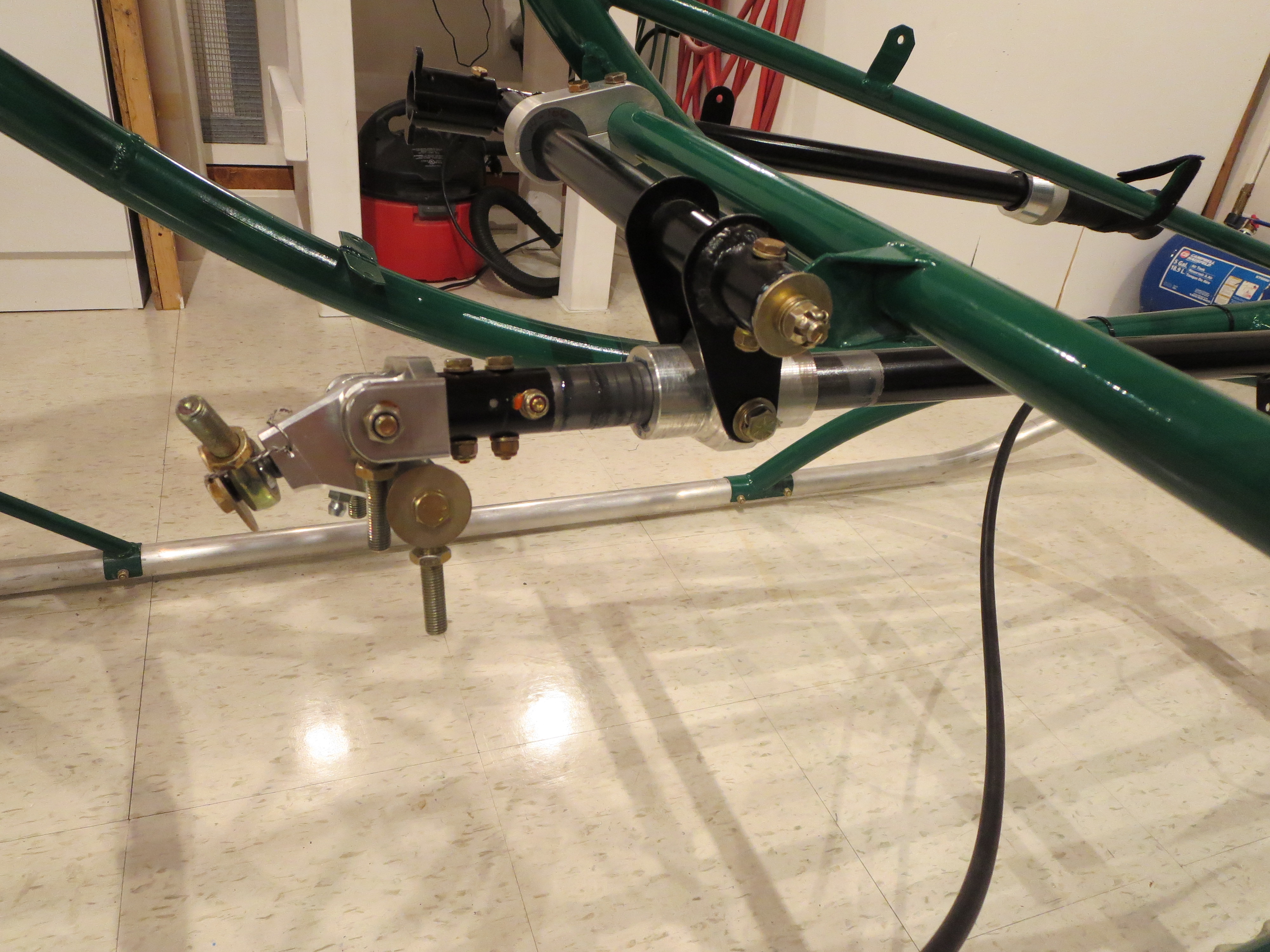
Everything is torqued and safety wired. I put a dot of torque seal on the nuts after final installation. Since all the pieces had been pre-fit, it was very straightforward. The only annoyance was that one of the Grade8 bolts I had purchased pre-drilled really wasn't drilled all the way through. It demonstrated that the Loctite sets up very quickly. The portion in the threads was already gummy after only an hour or so after installation.
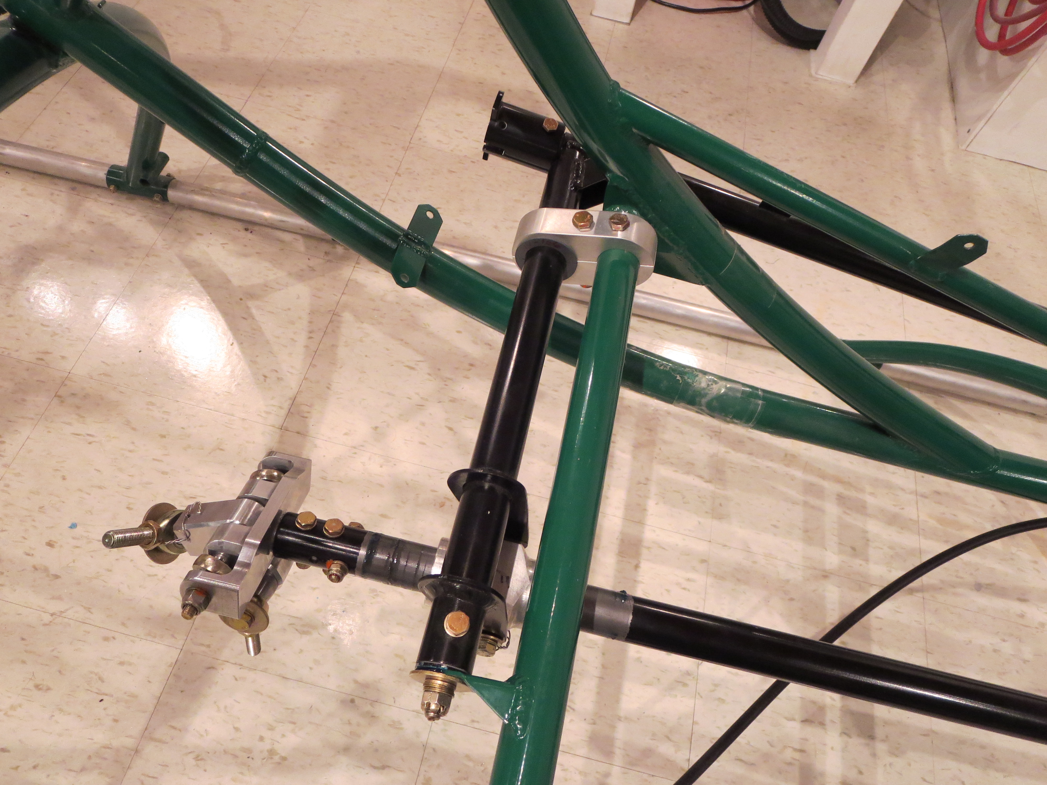
The control stick has almost no resistance fore and aft due to the bearings in the stick, but a slight amount in the left right since it is turning the cyclic shaft in the slider. It;s all greased well, and there is no breakout force, per se. We'll see how it all feels when the rest of the control arms and fittings are installed.
Mixer Assembled
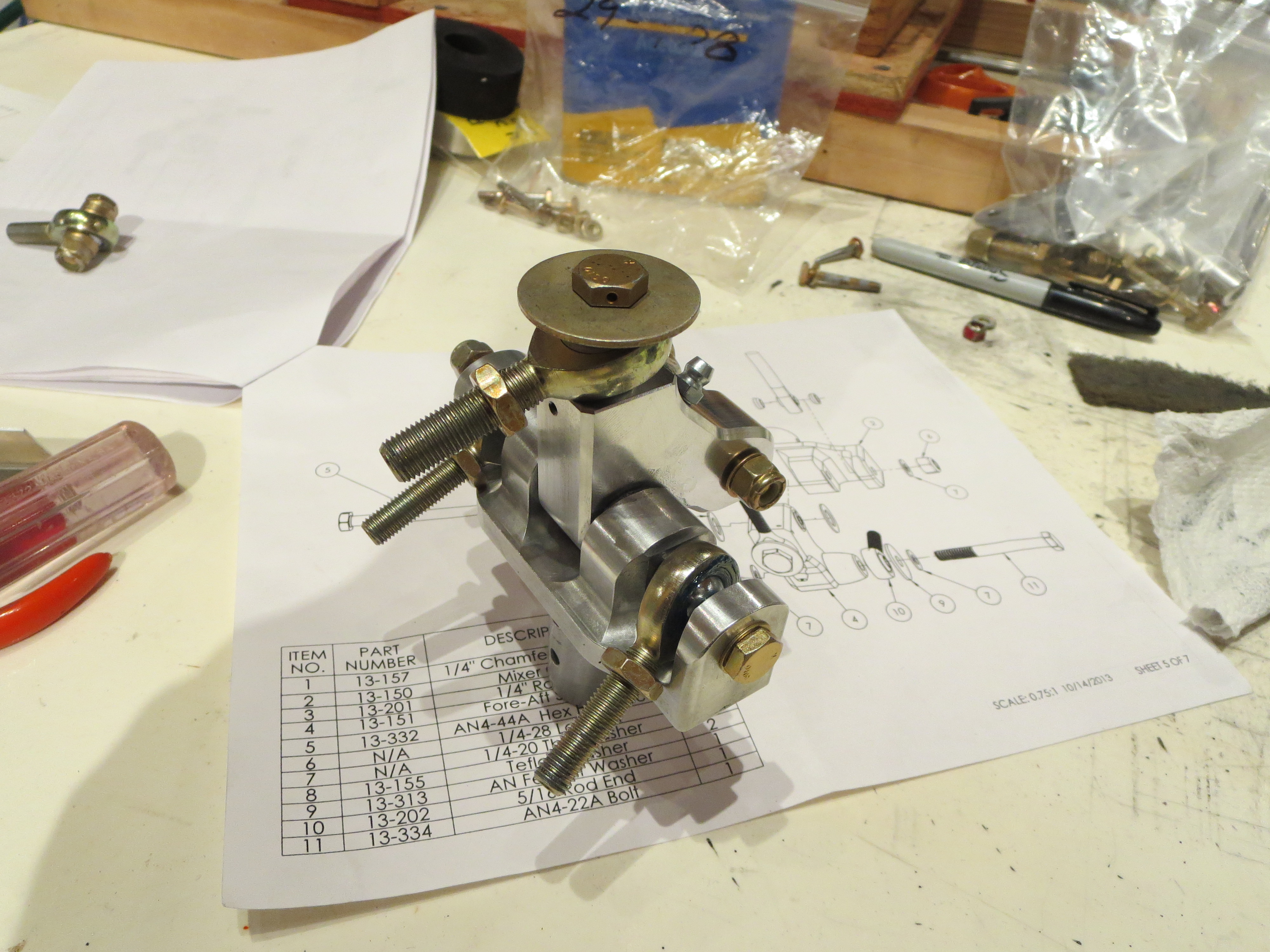
This is so much nicer than the original item. It looks and feels like a quality item.
Clutch Pre-Assembly
Next up is drilling the side plates to the clutch lever arm. I made use of my jig plates (from the cyclic tube mixer mount operation) to get a perfect alignment between the bolts and the holes for the plates.
Jig plates repurposed and alignment exact. It pays to make sure that mill is perfectly level and mill head is trammed. Then everything can be referenced to 0.0 degrees or 90.0 degrees.
It seems like a pain to make little jig thingies for a single operation, but I usually can find a secondary purpose for them which make the time spent much more worthwhile.
Complete clutch assembly pre-fitted (except rubber parts and bearing). Now I just have to tidy up the steel parts (they picked up some scale having sat for so long), prime, and paint. With the precision of the mill, and no broken drill bits, the pieces just fall together, snug and true. The clutch is a very simple assembly project.
Mixer Refit
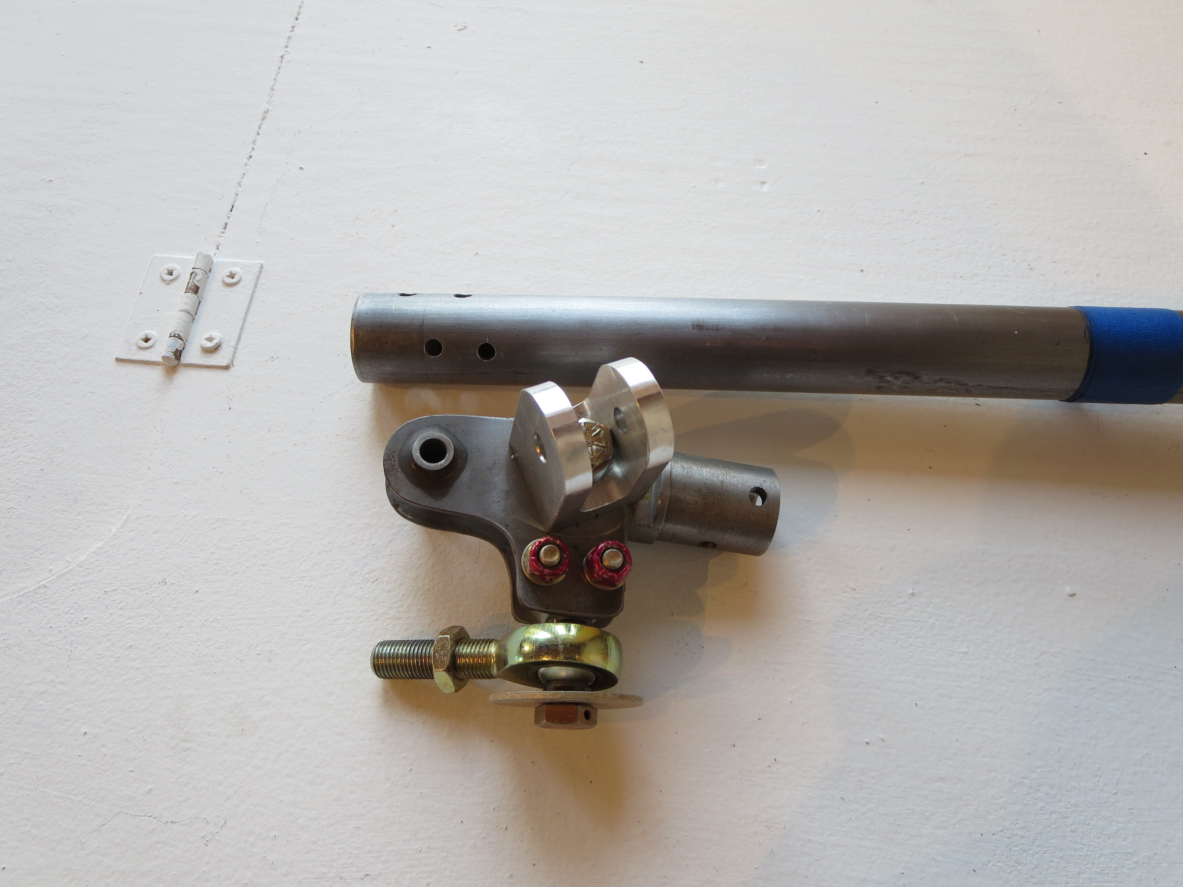
The original mixer (partially disassembled) looks fairly primitive next to the nicely CNC machined parts of the new one. I was never a huge fan of the single bolt in the center holding the "wings" together.

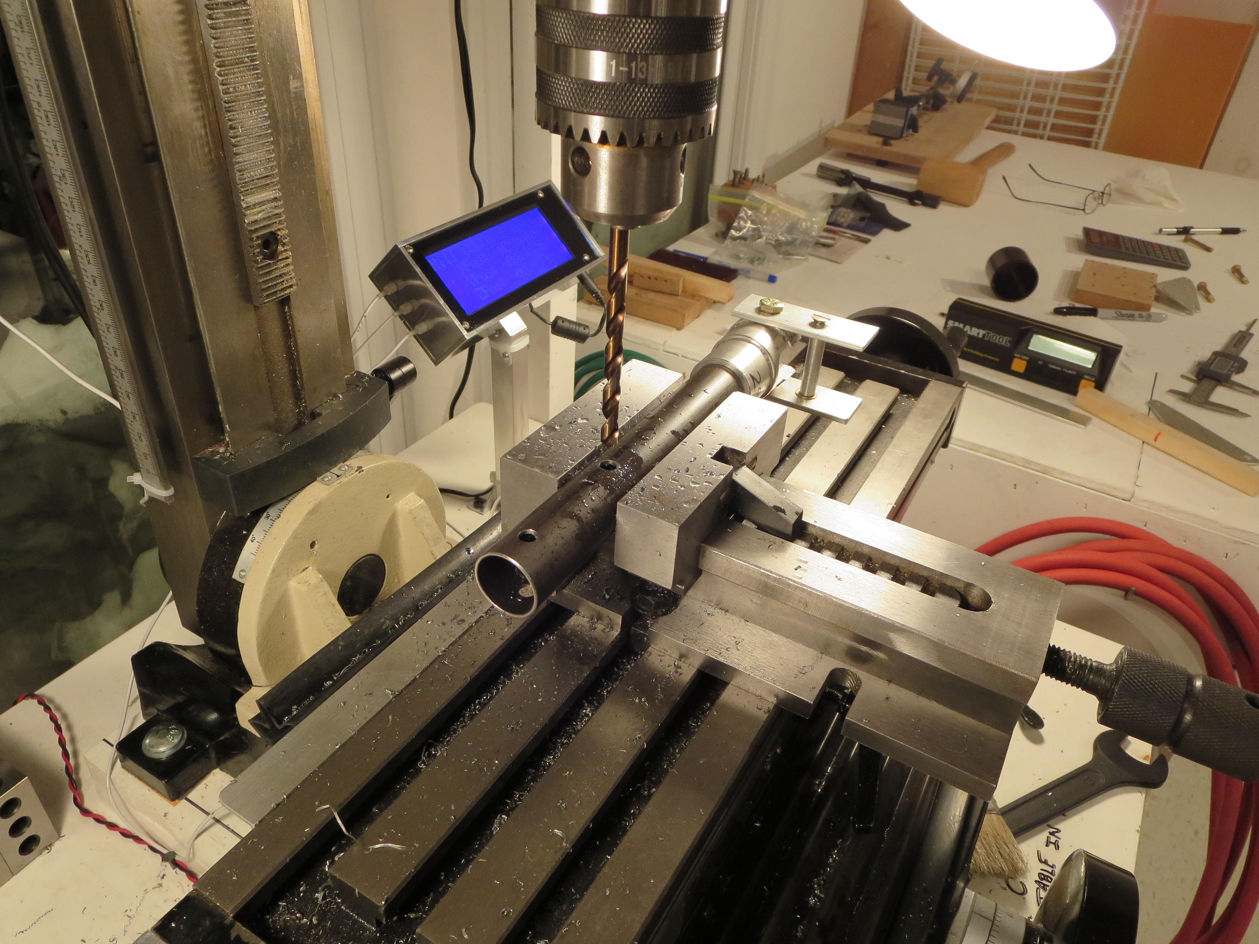
Start by drilling the hole for the safety wire on the fore/aft arm. On the collective slider I did them "free-hand". On this piece and with the mill and a couple of holding blocks this is achieved in very short order and with less hand wringing. Center punch the start location. Use a center drill to provide a "divot" so the real drill doesn't wander and away we go.
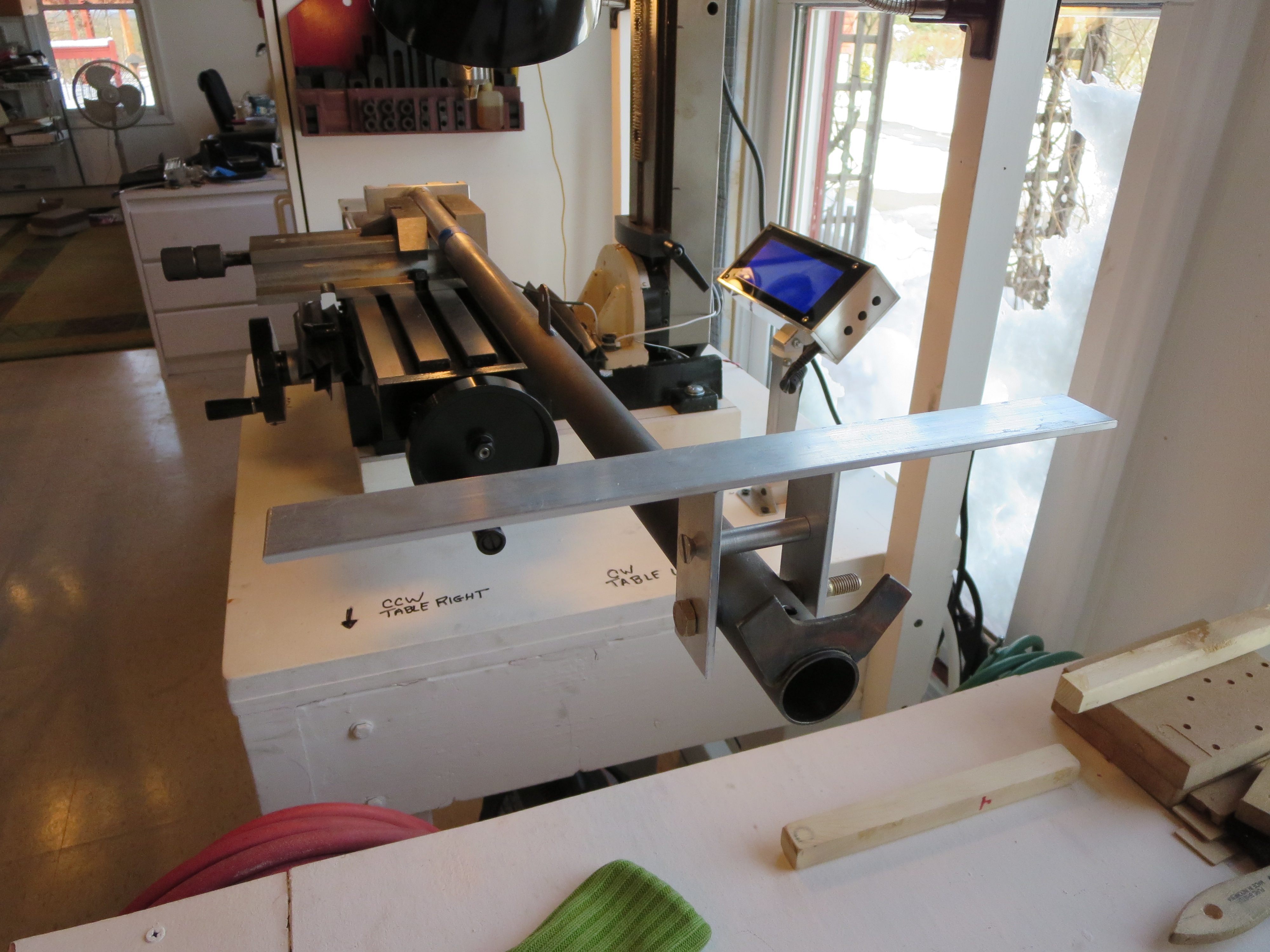
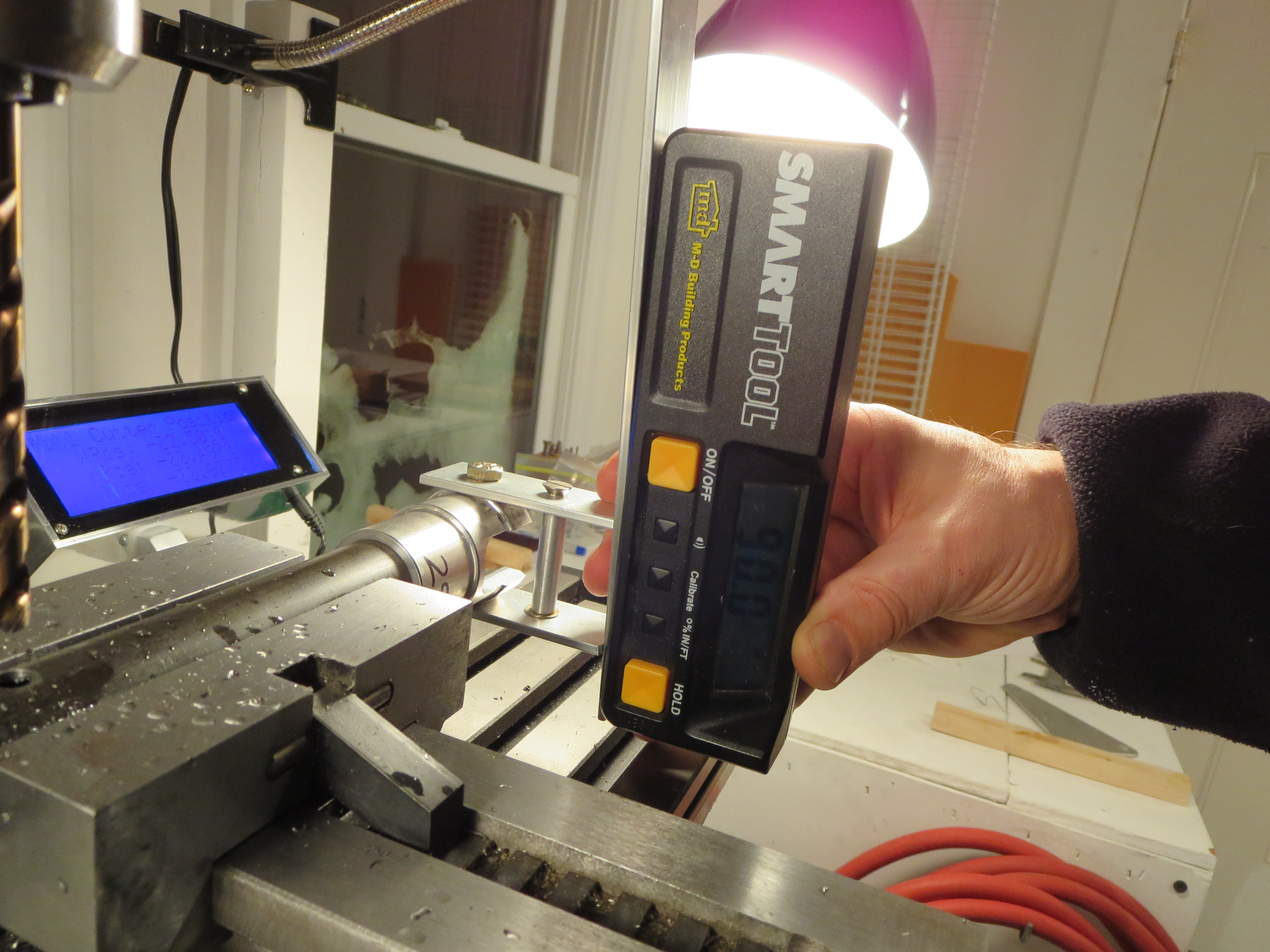
To precisely align the mixer with the control stick I made a little jig. Those two aluminum plates were machined in a stack, so they exactly match. The holes were drilled and the top edge machined to form a precise reference edge/plane. Both plates are exactly the same dimensionally. Then I made a little spacer on the lathe the exact same width as the cyclic bolt tube. Bolt 'em together and place a bar across the reference edges. My digital level was then used to get the angle between the reference and the bottom of the mixer block to exactly 0.0degrees.
Of course right when I was feeling smug and competent, BAM. The drill bit snapped off on the first hole. Crap! About half an inch into the hole. Of course you can't drill into a drill bit, so instead of boogering things up I stopped and stared at it for a while.
First I tried digging the broken bit out with a pick and needle nose pliers - no joy. Then I milled the hole slightly and the broken end of the drill bit. At least at that point I could remove the mixer block.
I tried using the "old" rearmost vertical hole first and matching the hole (you can see the hole on the left) Though very, very close, the hole on the other side of the tube was slightly oblong (by about 10 mils). I went ahead and drilled the horizontal cross bolt.

Why the bit snapped I don't know. It was only eating into aluminum at that point. It was well oiled, and I was backing it out regularly to clear chips. I was attempting to use a #30 bit as the pilot and that is probably a little wimpy for a hole this deep. Here you can see the remains of the broken bit with about 0.5" missing (in the mixer block).

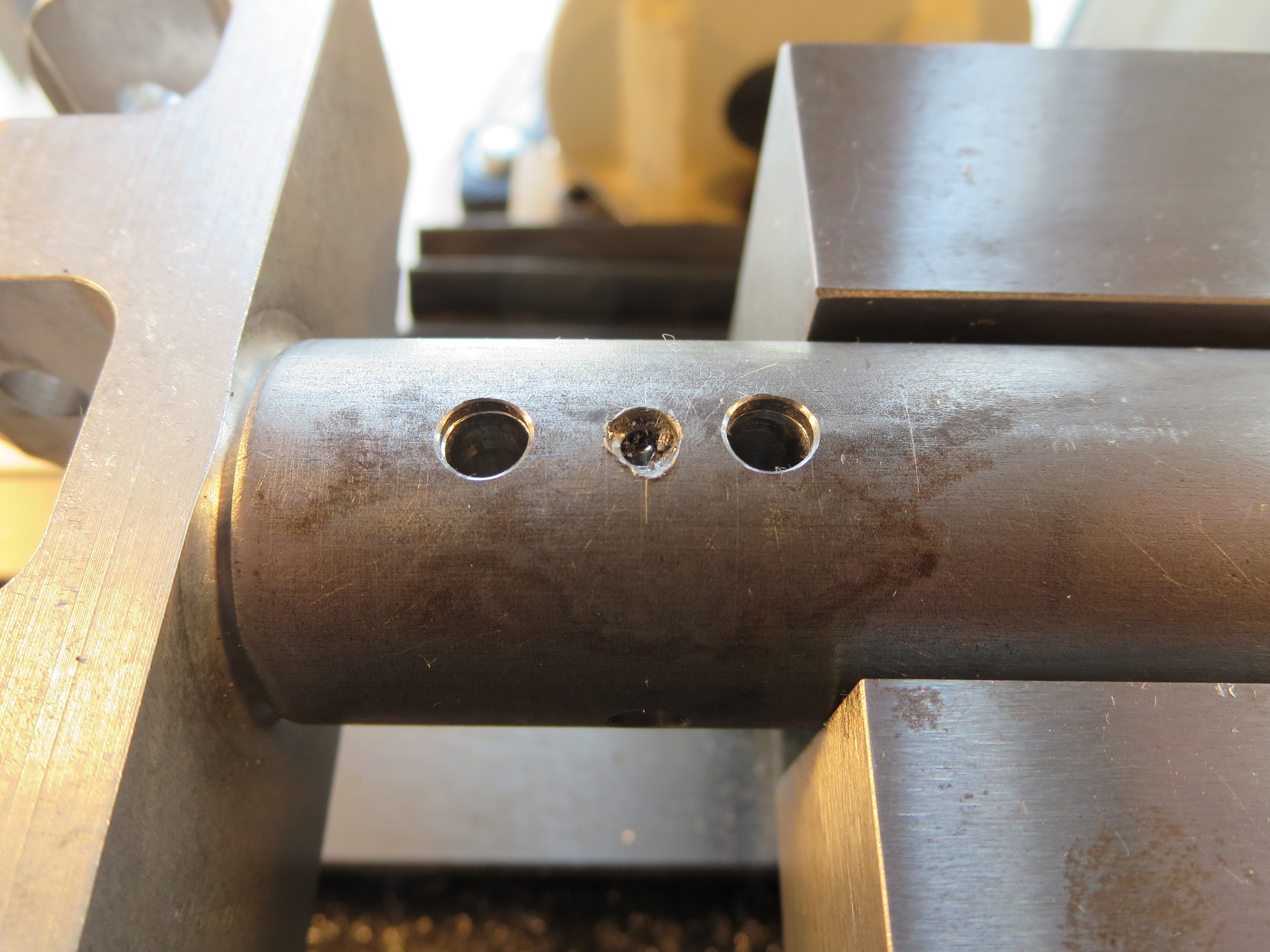
Even though it probably would have been OK, I carefully measured and determined that there was room for a third hole in between the others. You can see the middle drill bit here showing that hole. Pretty busy. The forward most cross hole is perfect, nice and snug. The rearmost one is the one I tried to match - sloppy on the far side. The middle is my auxiliary hole - also nice and snug. OK. Good. Crisis averted.
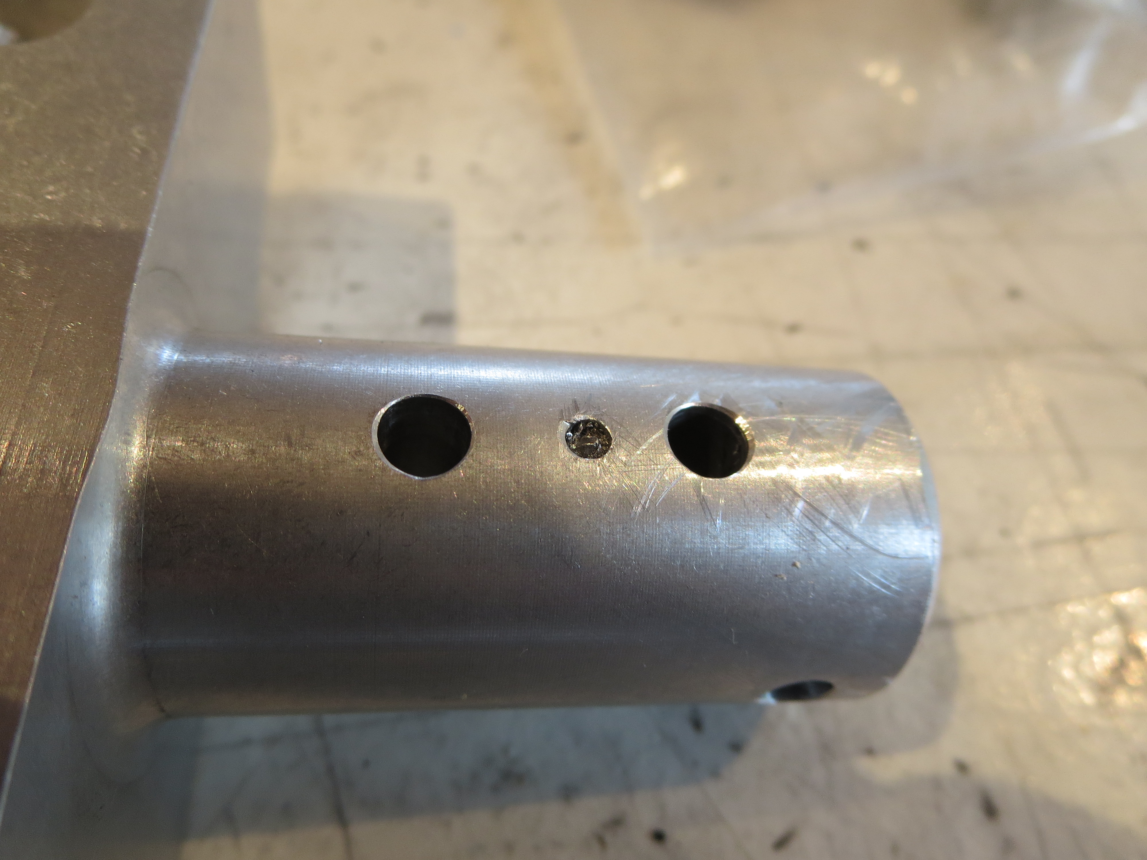
The mixer block removed from the cyclic control tube showing the three holes. Since it is solid aluminum I have no concerns over strength. The broken bit will ride along with me forever stuck in the aborted hole.
The rest of the mixer assembly is a non-event, just assembly with a little sanding to make everything slide together smoothly. Off to paint.
Received New Mixer
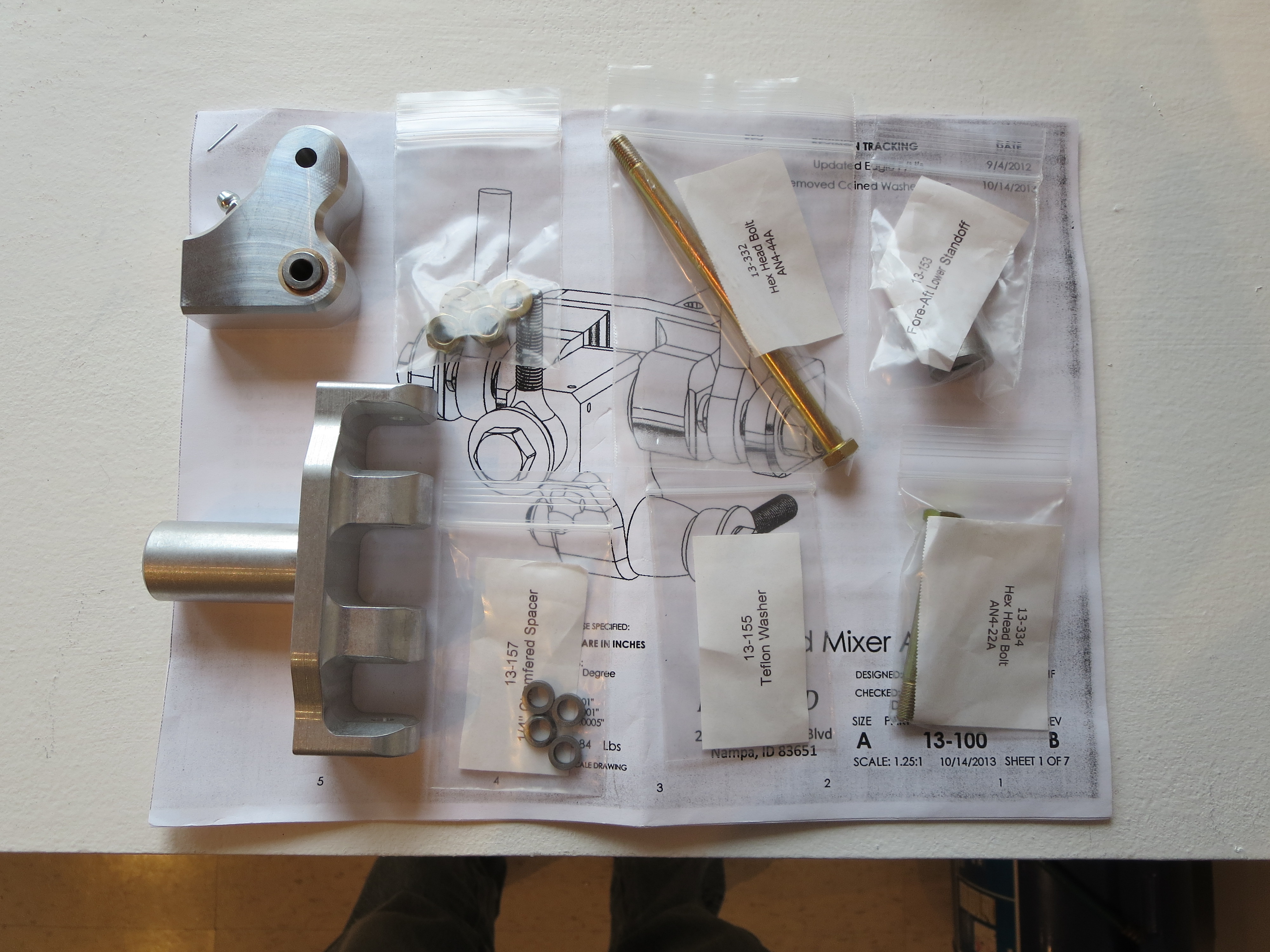
I finally received the new mixer from Blake. Very nice machined parts. What a quantum difference in quality of drawings CAD makes. Can't wait to slide al this together.
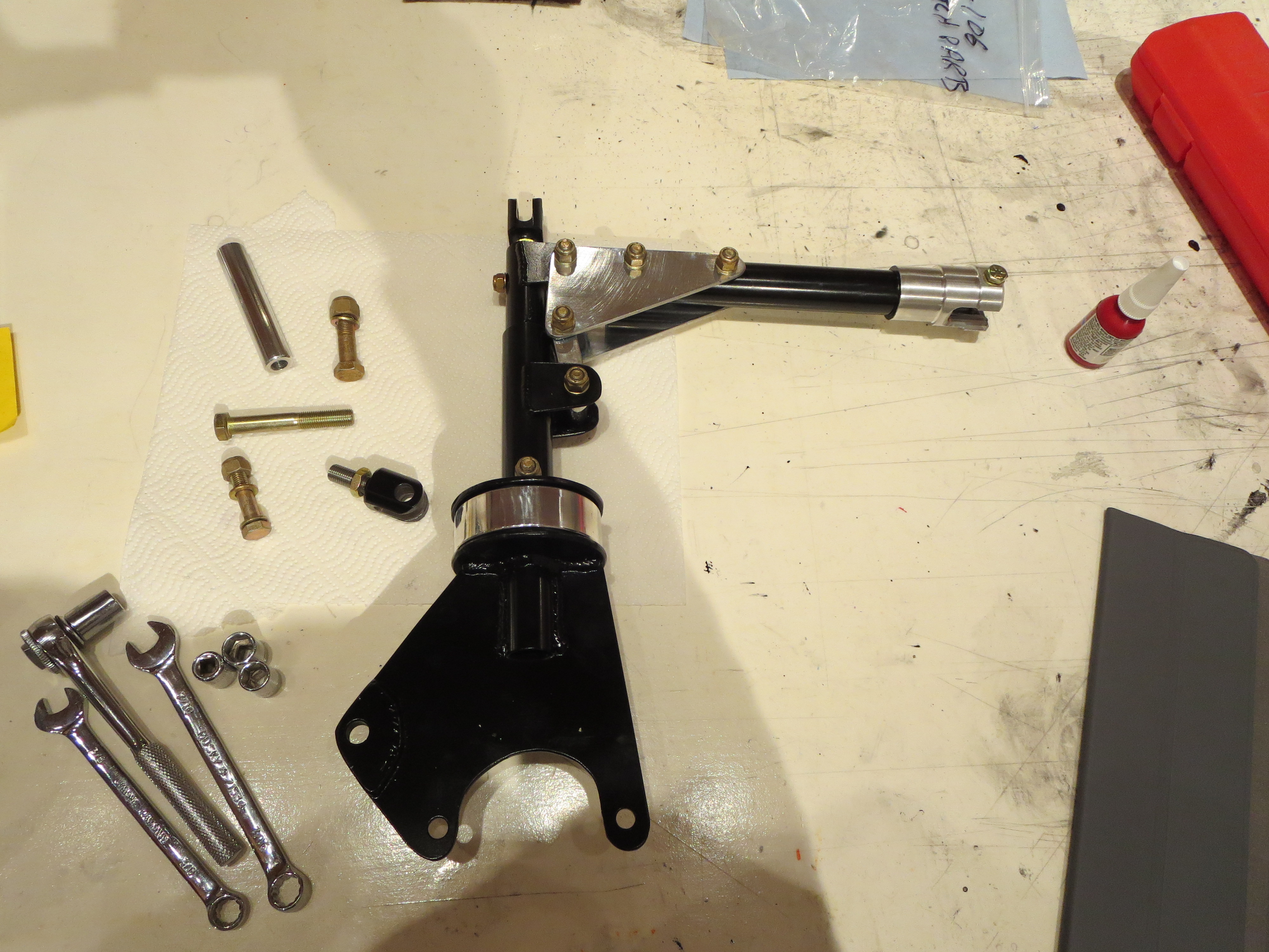
Final Pedal Mounting
I went to FINAL mount the TR pedals as it is time to start placing some things on the ship for the LAST time now. When I went to snug the bolts up it all bound up and was very stiff. Not good. Controls are supposed to have some damping, but should be butter smooth with no stiction.
After staring at it for a few minutes it became apparent that when the AL bushings are snugged up, they get pulled against the welded steel tabs that mount them to the frame and those tabs are not perfectly square with the mate on the other side of the frame for the opposing bushing. That "tilts" the bushings and cause them to bind in the tube.
No problem. I have all these machine tools - time to put them to use. I lathed down and threaded an aluminum rod that was the appropriate length to thread into the bushing to "point" to where the alignment was on the opposite side.
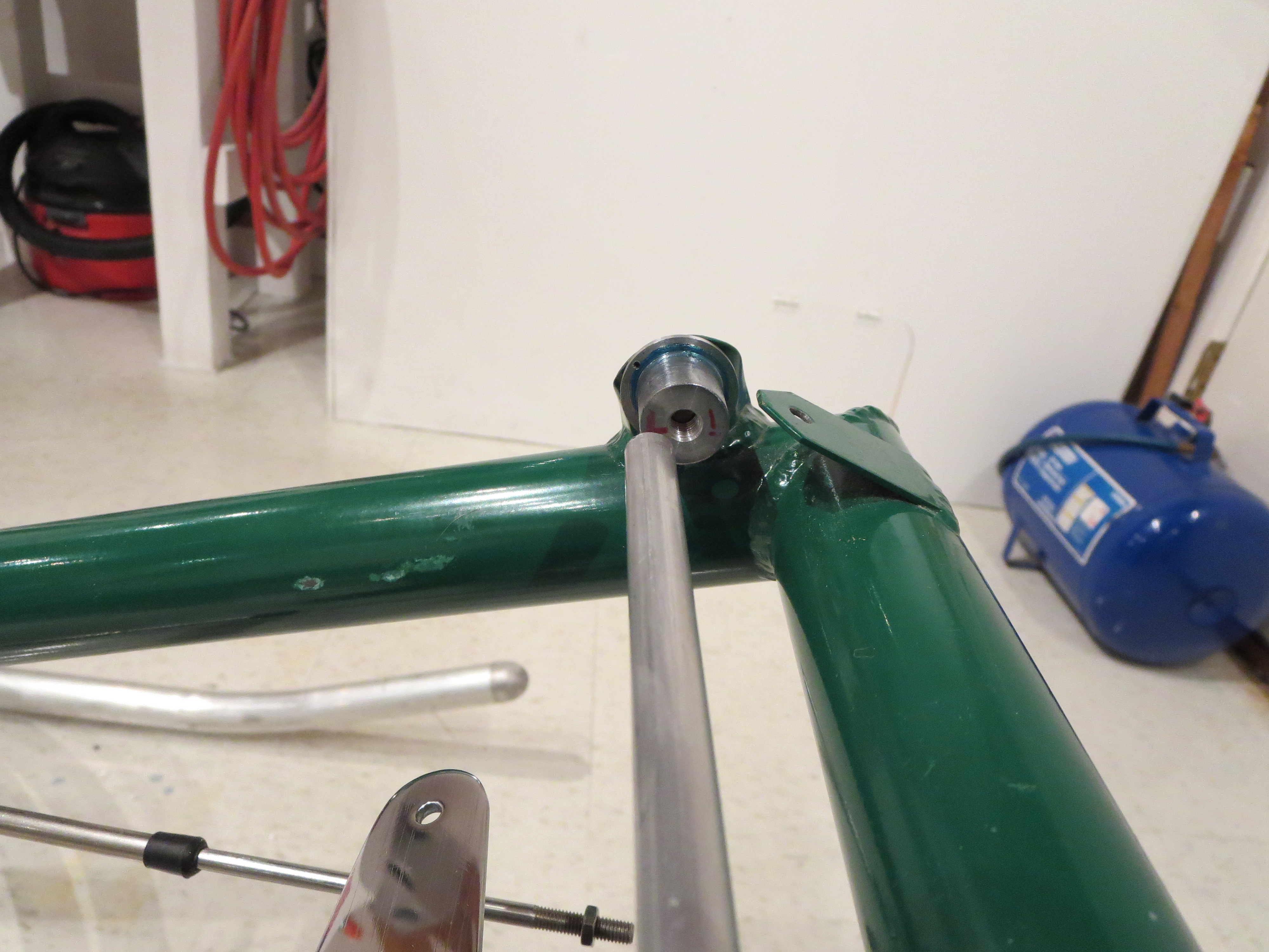
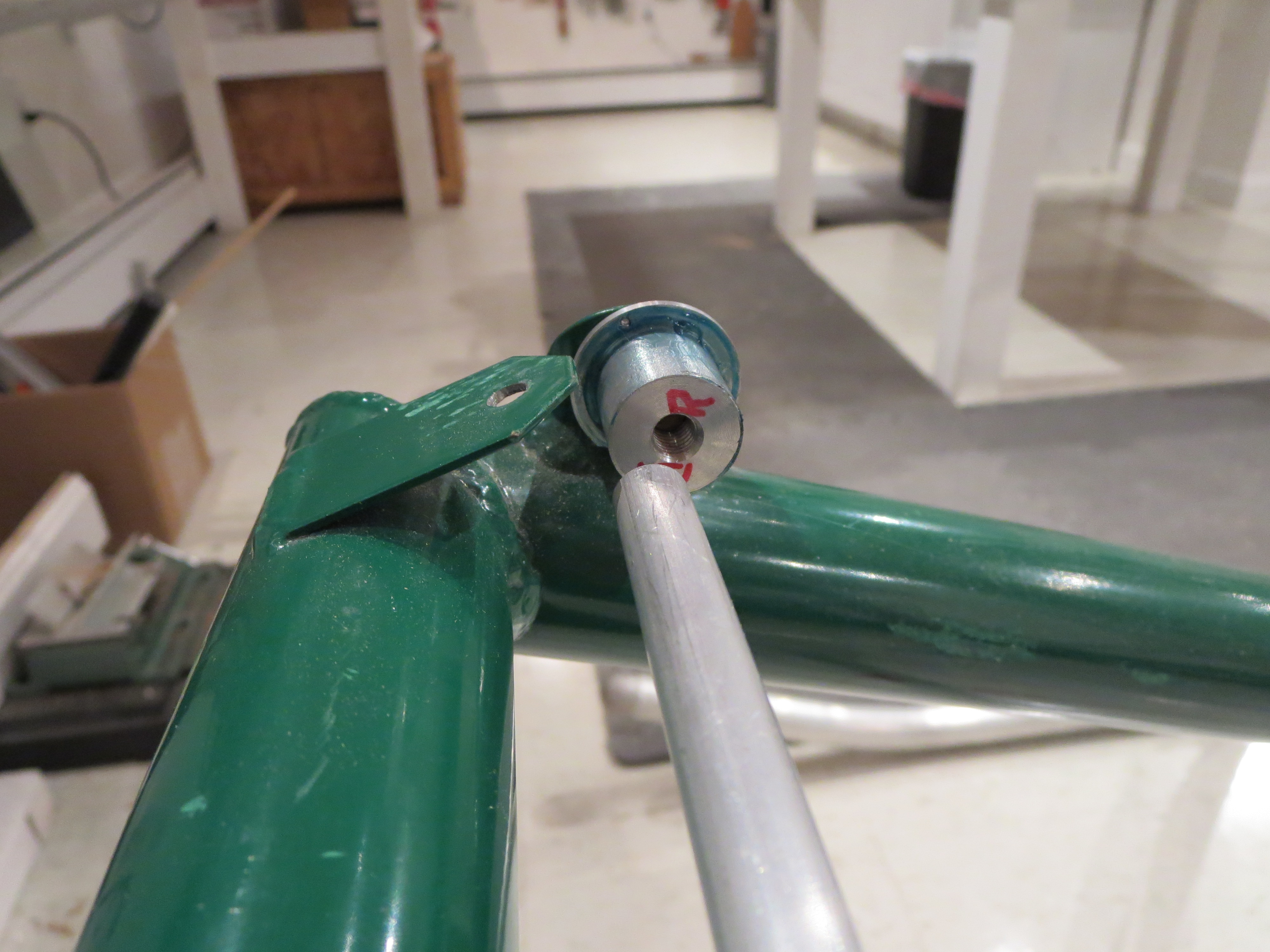
With those very evident visual cues it was very easy to tweak the mounting tabs (it didn't take much) to bring everything into nearly perfect alignment.
Amazing how such a small change resulted in such a large difference in the feel and operation of the pedals. Greased up, snugged up, Safety wired. The first permanent moving part. Lots to follow in a short period. Nice.
Lower Panel Crafted


Start with a quick CAD model of the instruments and panel. If anyone is interested in the solid models I used, just email me and I will post them.
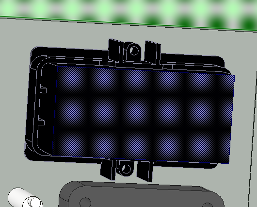
I almost neglected to model the rear retaining ring around the Red Lion tach. Can;t skip that because it's quite a large thing. Once everything is modeled, it is easy tp check for interferences and tweak the position if required.
Once the modeling is complete, add some dimensions and make a detailed drawing as I did HERE. This is the primary reference sheet when machining the holes in the sheet.
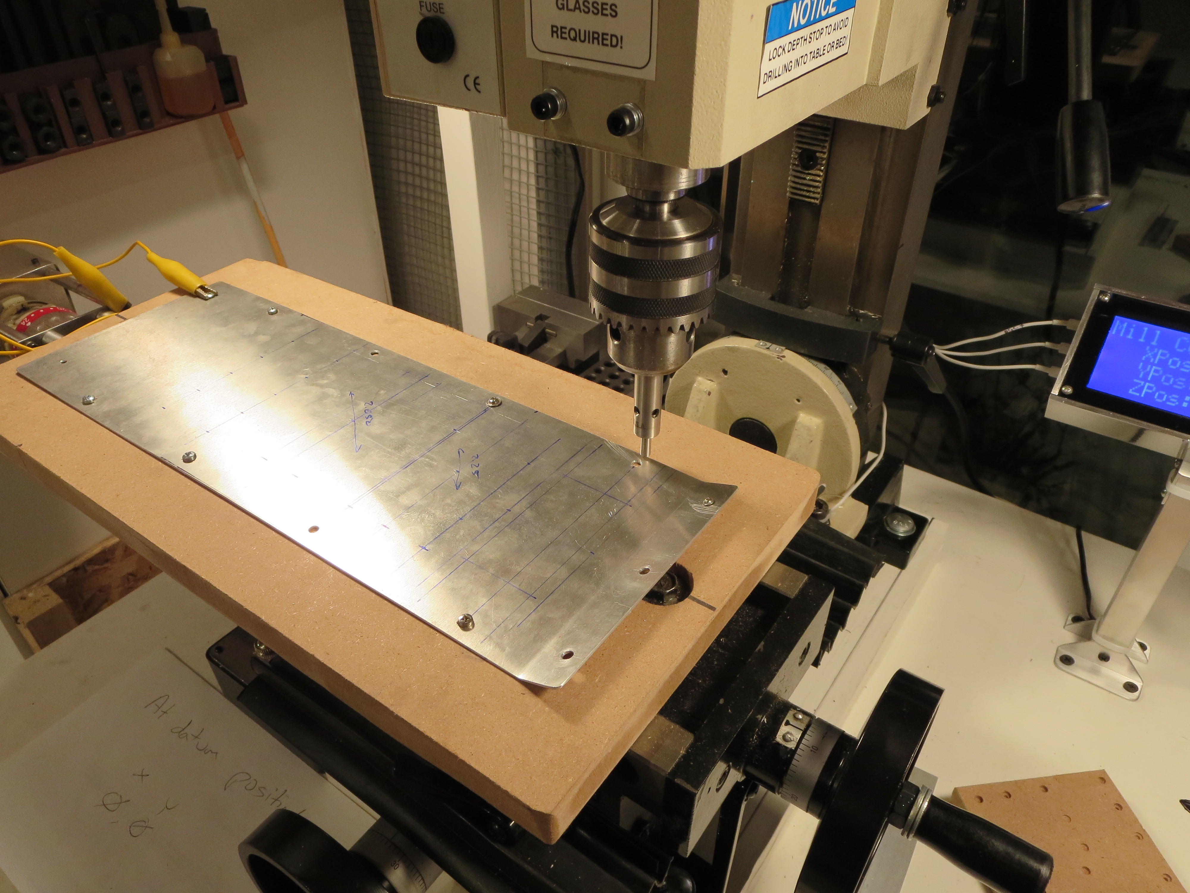
The blank queued up on the mill. Prior to this the blank had been cut and then fit into the instrument pod lower. The side mounting screws were drilled in assembly with the support strips in the pod. Perfect alignment prior to this drilling/milling operation.
On the mill I bolted a piece of MDF to the table (mounting bolt recessed, of course). Then the blank was trammed to the mill so the edge was in perfect parallel alignment with the quill. Very small wood screws are then screwed through the mounting holes to solidly affix is to the plate. The front mount hole and edge are the home reference.
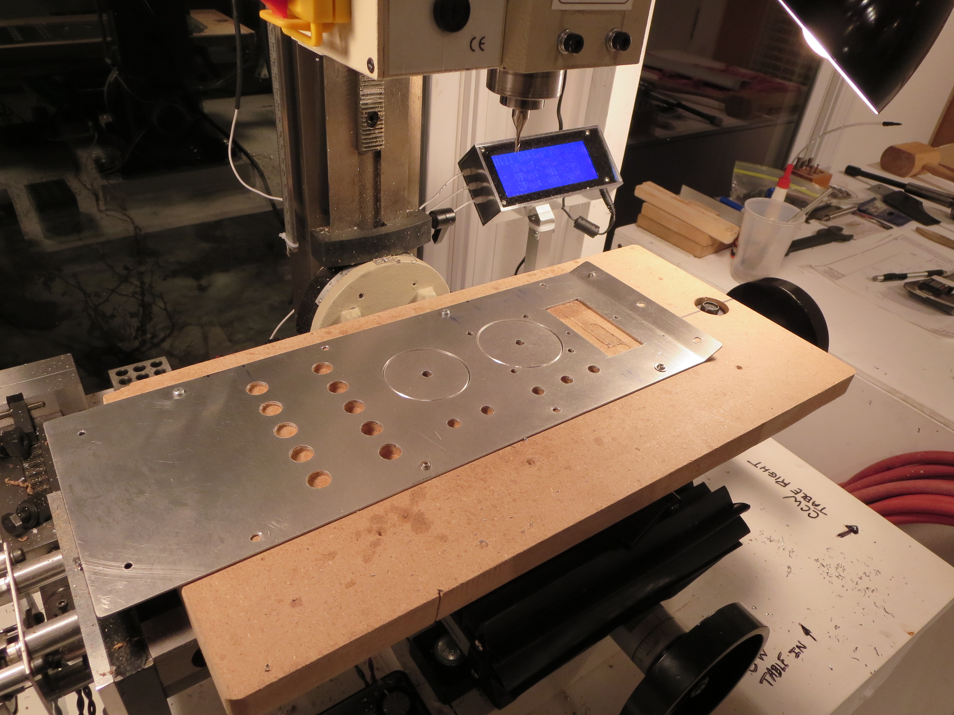
The Lower Panel machined. I love that little mill. Though time consuming, the accuracy is impressive. Digital readouts on each axis make repeatability and accurate positioning very easy. I used my hole jig for the circles, and milled out the tach square with a 3/8" end mill. The corners were finished with an 1.8" end mill. If needed I will file them down.
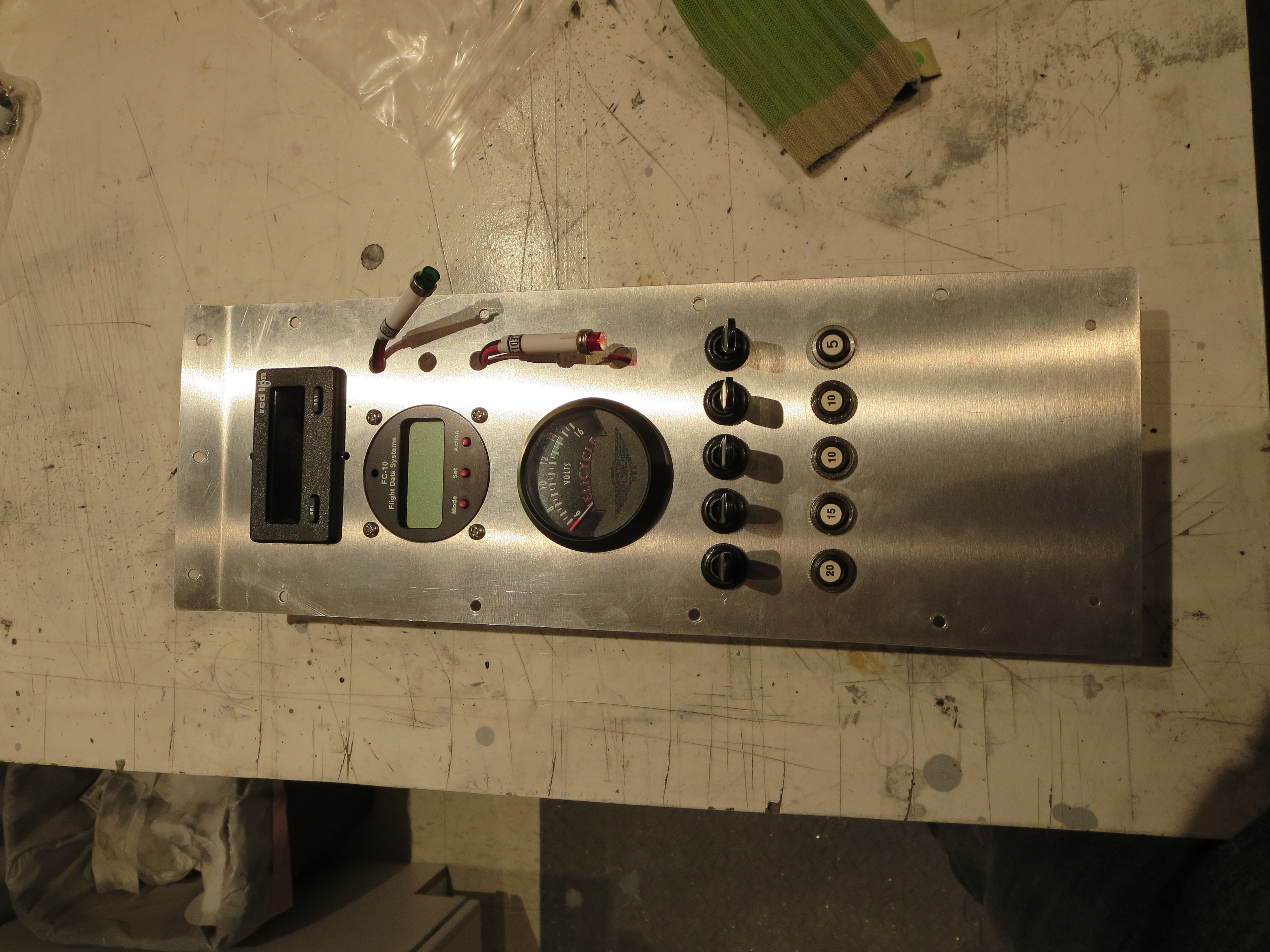
All the stuff preliminarily fitted. My holes for the indicator lights were a bit small and the fuel monitor hole needs some trimming, but by and large the fit is pretty good. All the holes are alignment nicely and very square.
DVD Index
I finally got around to indexing the contents of the DVDs. At this point I need to find certain things quickly. All the DVDs have been loaded onto my iPad so I can reference them quickly in the shop. Also shown is the order in which the items should be completed for final assembly.
| DVD Contents | ||||
| DVD | Group | Sequence | Subject | SDM Order |
| 1 | 1,2 | 1 | Full and Half Door Construction | |
| 1 | 1,2 | 2 | General Construction and Fitting Landing Gear | 1 |
| 1 | 1,2 | 3 | Cabin and Trim Fins- Floor Pan, Pod, Cabin, Windscreen, chin window | 2 |
| 1 | 1,2 | 4 | Cabin and Trim Fins continued - Trim fins and mounting. | 3 |
| 2 | 3 | 1 | Fuel System | 4 |
| 2 | 3 | 2 | Direction Controls, Cyclic Controls | 5 |
| 2 | 3 | 3 | Fitting of Controls to Ship | 6 |
| 3 | 4,5 | 1 | Main Transmission Fitting and Lift Strut | 7 |
| 3 | 4,5 | 2 | Tail Rotor shaft construction. TR gearbox. Tailrotor fitting. | 10 |
| 3 | 4,5 | 3 | Tailrotor balance and general information about design | 8 |
| 3 | 4,5 | 4 | Tailrotor gearbox mountings and alignment | 9 |
| 3 | 4,5 | 5 | Control rod fitting and swashplate alignment. | 15 |
| 4 | 9 | 1 | Turbine engine installation and control information | 12 |
| 4 | 9 | 2 | Governor construction and installation notes. | 13 |
| 4 | 9 | 3 | Turbine plumbing and fittings. Clutch Assembly. | 11 |
| 4 | 9 | 4 | Motor mount fitting and alignment | 14 |
| 5 | 6,7 | 1 | Rotor head fitting. | 16 |
| 5 | 6,7 | 2 | Rotor Blade Doubler Bonding | 17 |
| 5 | 6,7 | 3 | Rotor doubler continued and end caps. | 18 |
| 5 | ,67 | 4 | Rotor mounting and balancing. | 19 |
| 6 | 8 | 1 | Battery Box Mounting and general wiring information | 20 |
Finished Packaging Compass
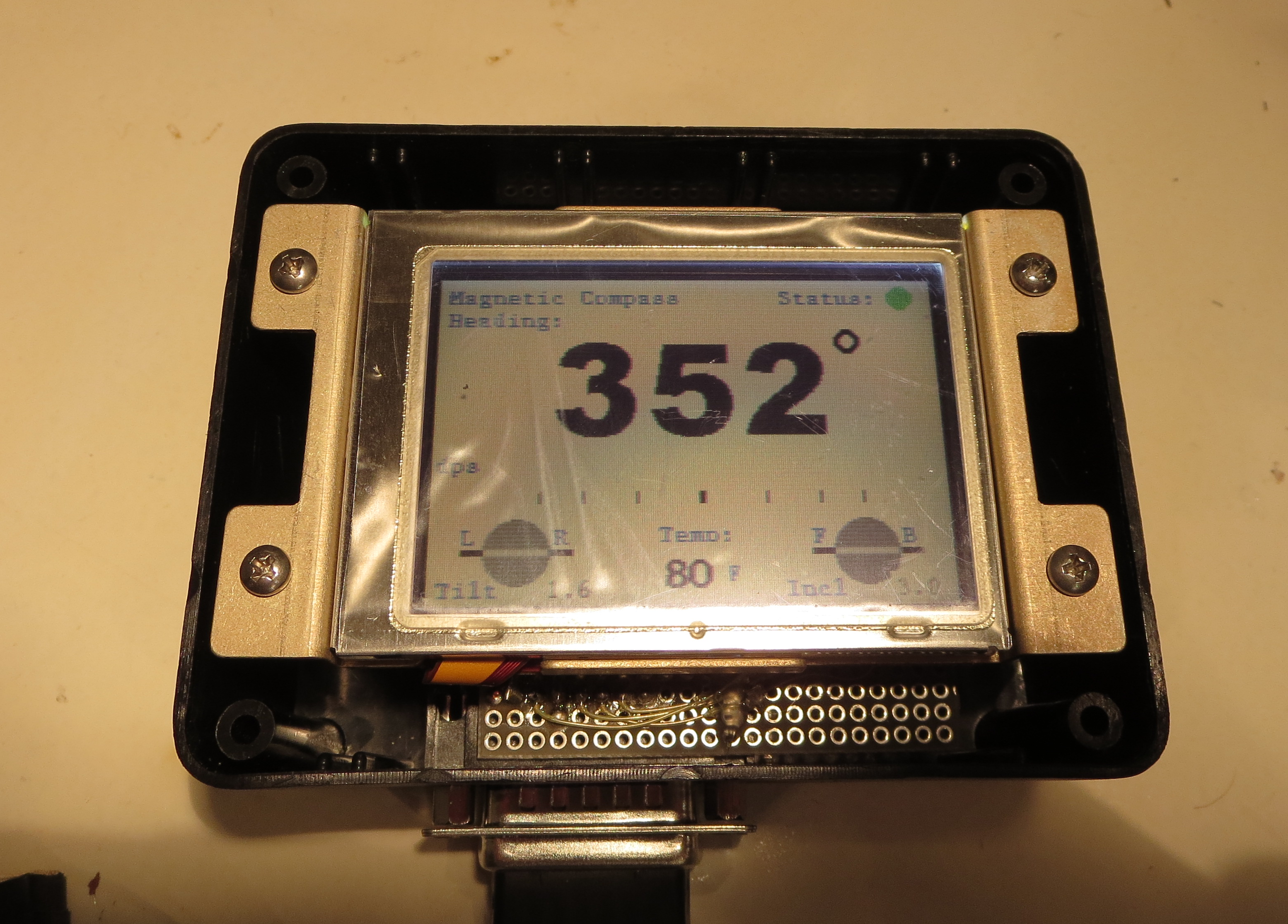
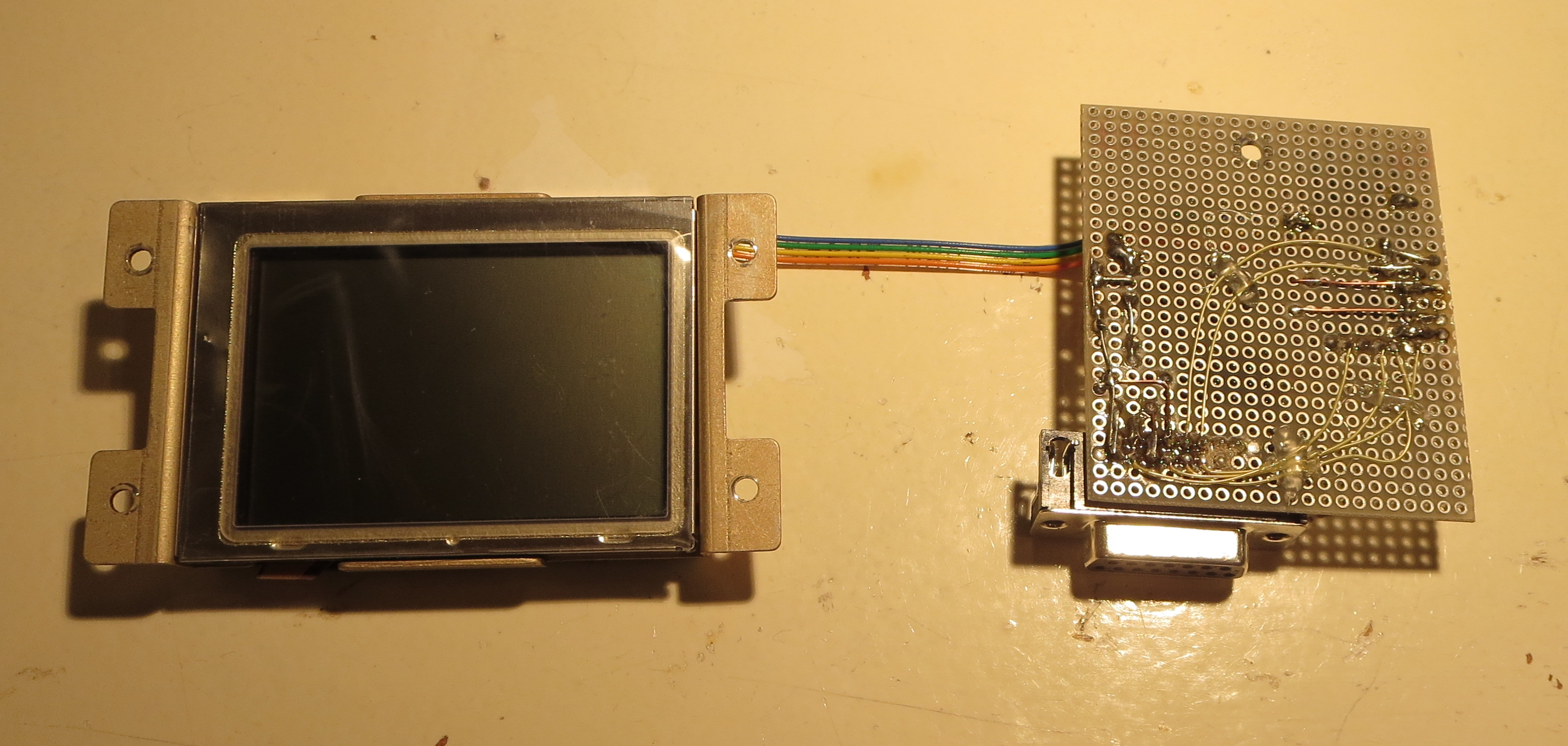
I finally finished packaging my homemade electronic compass. Small project box with some machined risers to house the thing.
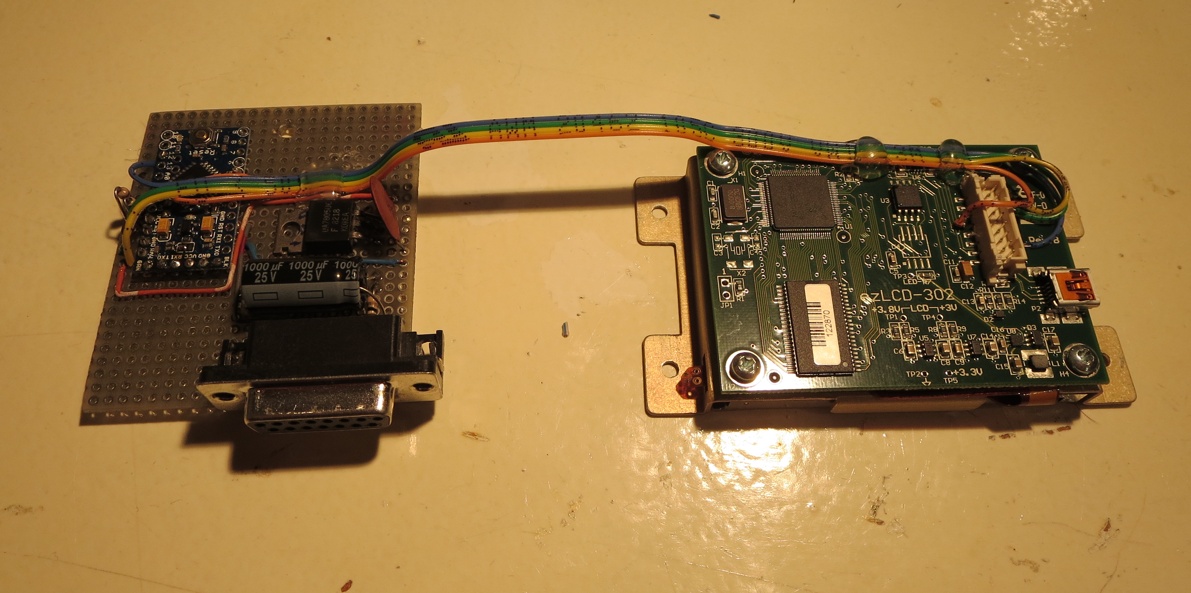
That's just an experimenter board with the Arduino mounted and a 7805 linear power supply. Power draw is 0.18A at 12V, so about 2.2W. More than I expected, but not too bad overall.
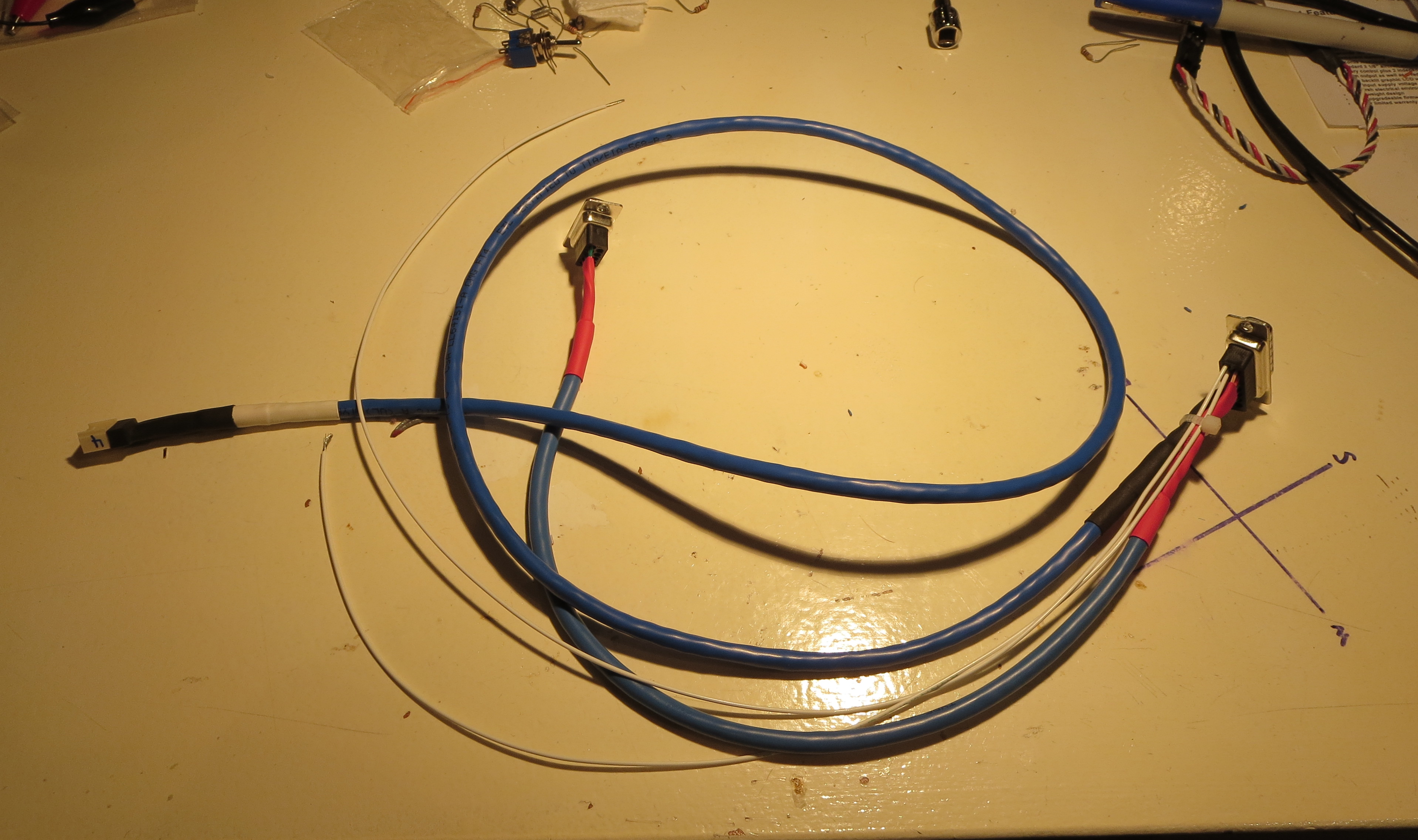
Custom wiring harness connects to unit, power, sensor, and a DSUB9 in case I want to update the firmware with calibration data once its in the bird.
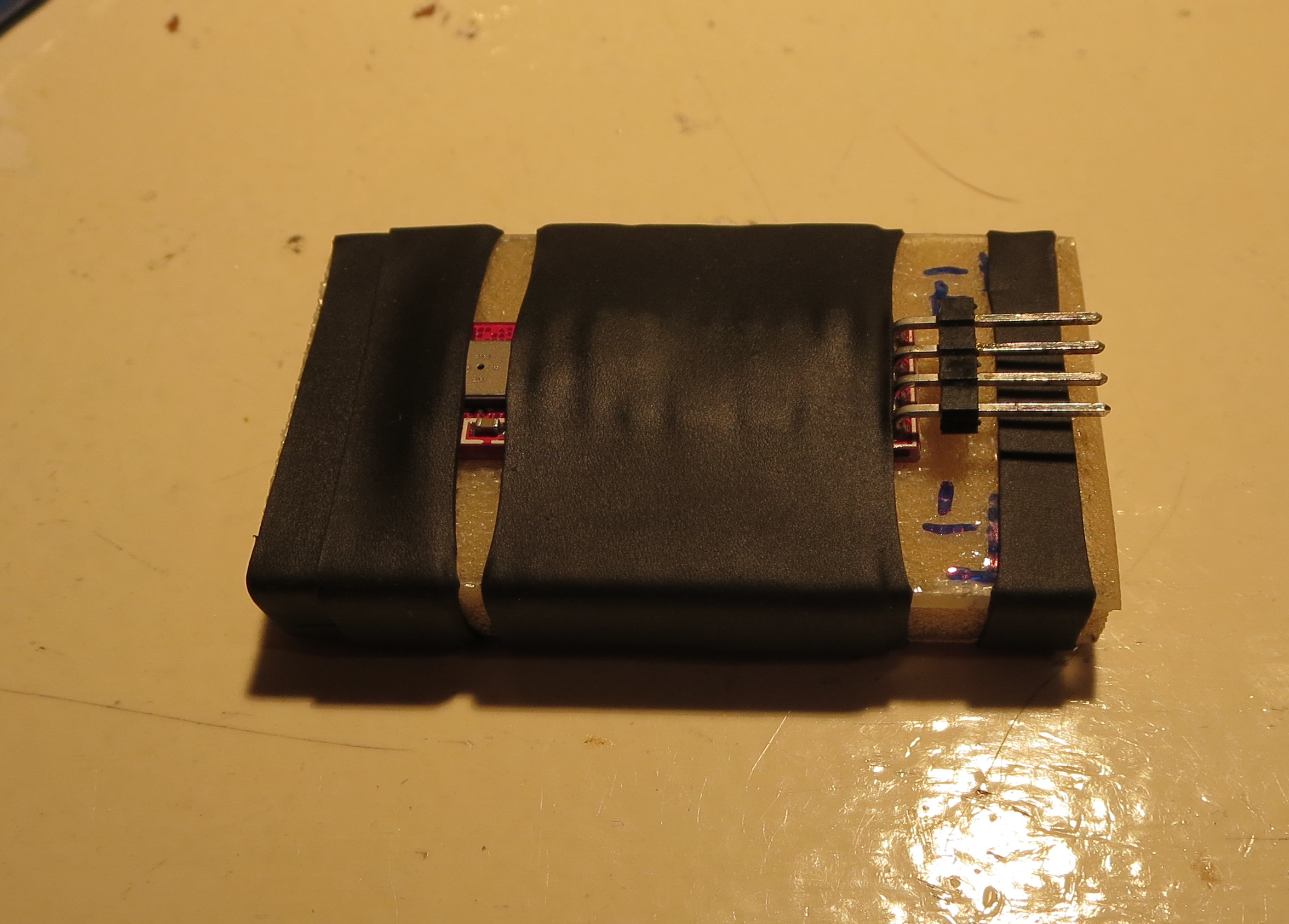
Sensor is shrink tubed to a little chunk of fiberglass. I will probably just tie wrap this to a fiberglass platform at the from of the pod's interior.
Wiring notes are here. I uses NotesPlus HD on the iPad to take hand notes in the shop. Better than paper and you get an instant electronic copy.
N-Number Reserved
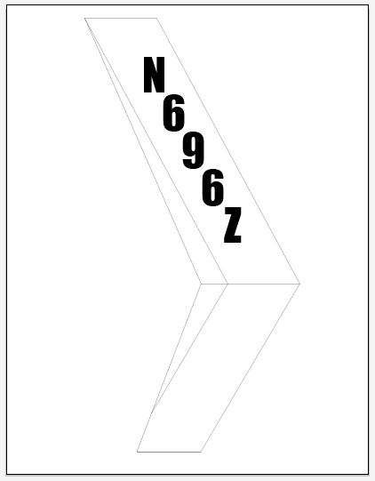
Hooray! I got notice of my reserved N-Numbers from the FAA today. Though not difficult to get or an especially tricky milestone, it IS an indication of the project progressing.
I ordered some custom vinyl lettering from DIYLettering.com; Pre-cut green vinyl letters 3.5" tall. The font is "Impact", which looks very readable.
Panel Wiring

Instrument Cluster wiring harness is fabricated and installed. This is not especially hard, just tedious. I did not do a formal schematic since there is no real circuit design here, just connecting point A to point B. It was all tracked with spreadsheets. Once routed and the ends crimped, the bundles were lashed with spiral wrap nylon to tidy everything up. I drilled holes on the back of the GPS/COMM tray so everything could be hard-secured down. No wiggling wires. It is all very solid.
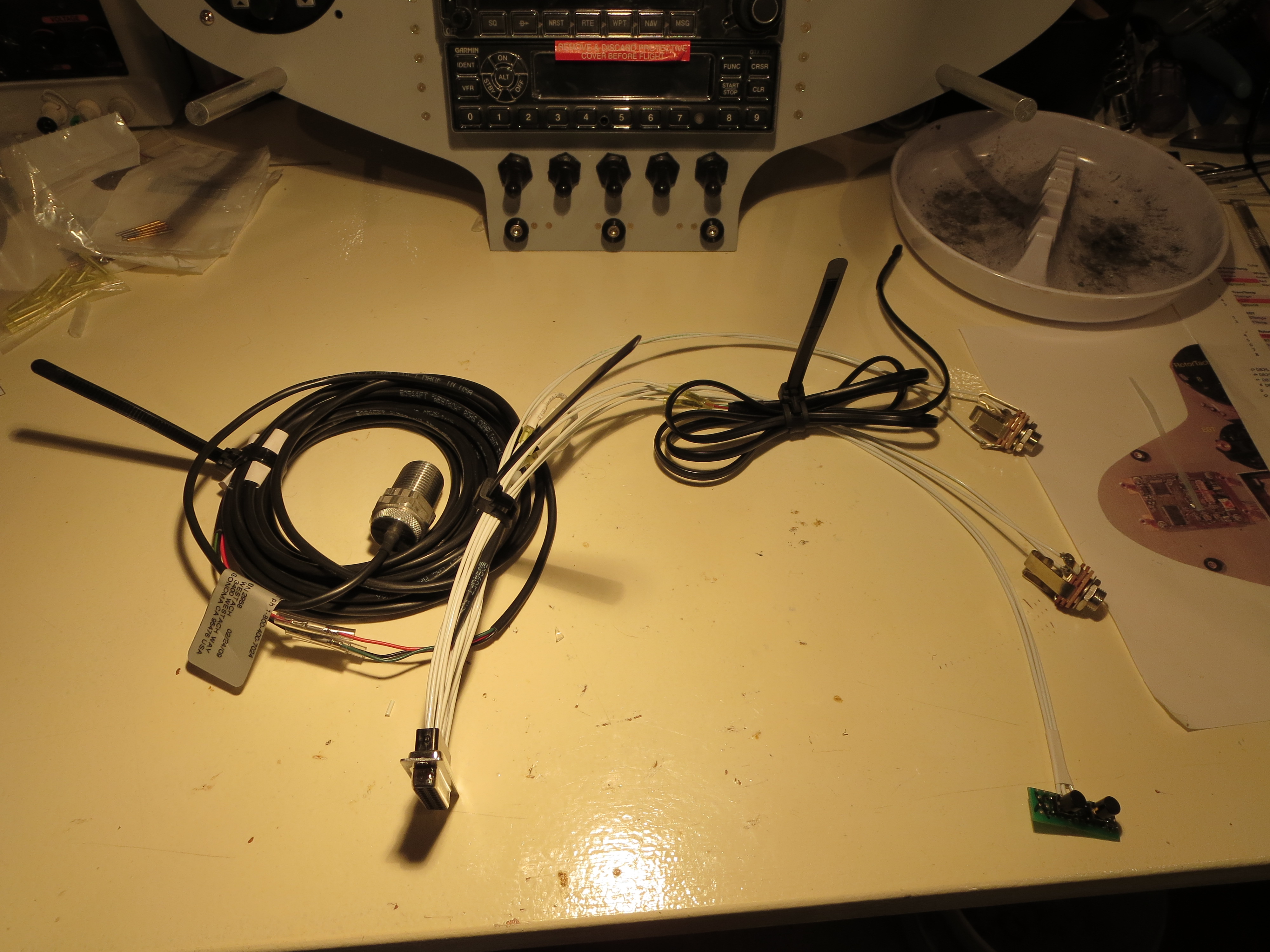

Of course once the wiring was done I had to make up a little test harness with power and switches for the XMIT and COMM flipflop as well as power and the sensors that NEED to be attached when powered up (the tach sensor).
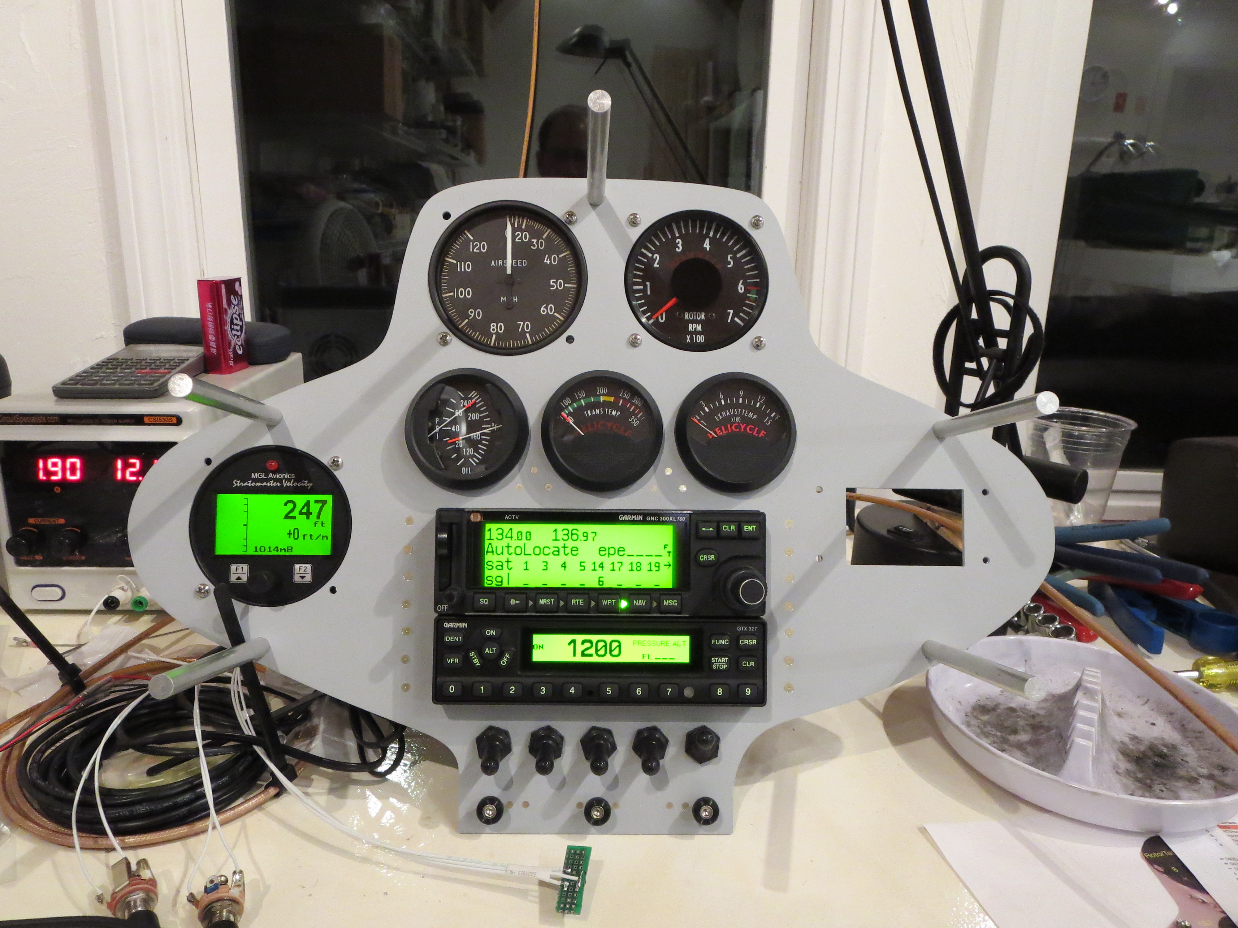
Ahhh the money shot! Everything powered up and is functioning OK as far as I can tell. I rigged up antennas and could send and receive over the radio to my handheld and get GPS position data accurately.
One thing that became immediately apparent is that the COMM draws HUGE current (comparatively) when transmitting versus receiving. Nominally the panel was drawing just under 2 amps, but it spiked to about 4 amps, and quickly dropped to 3 amps when transmitting. Wow.