
Gearboxes
Pulley Balancing
11/01/14 12:52 Filed in: All
In an earlier post I showed how I lathed off most of the lugs for the fan blades on the main transmission pulley. I mentioned this to Blake at Reno and he indicated that I should rebalance the pulley more carefully than I had. The lugs are not uniform and the weight removed is not perfectly symmetric.
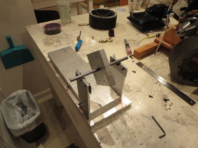
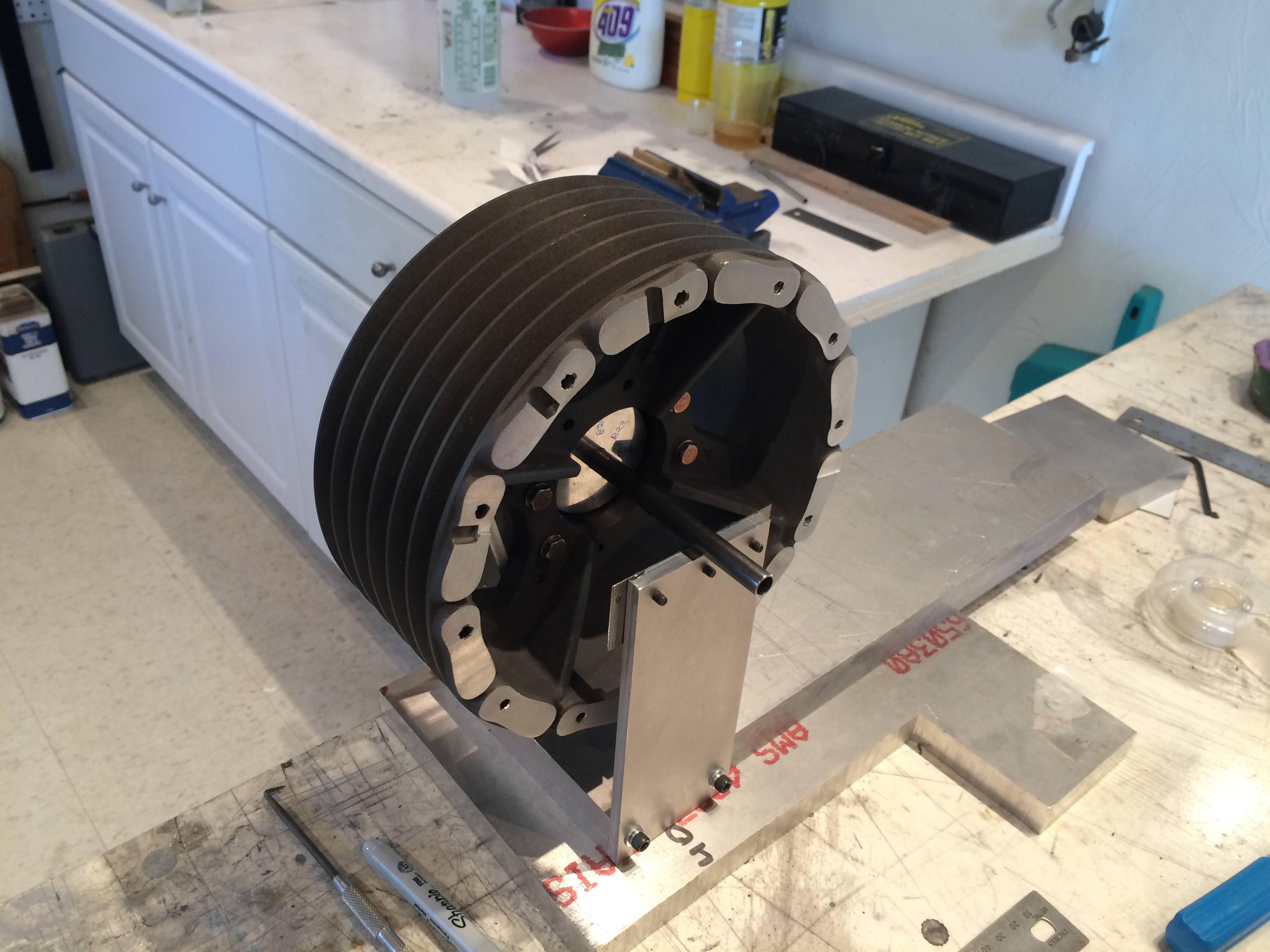
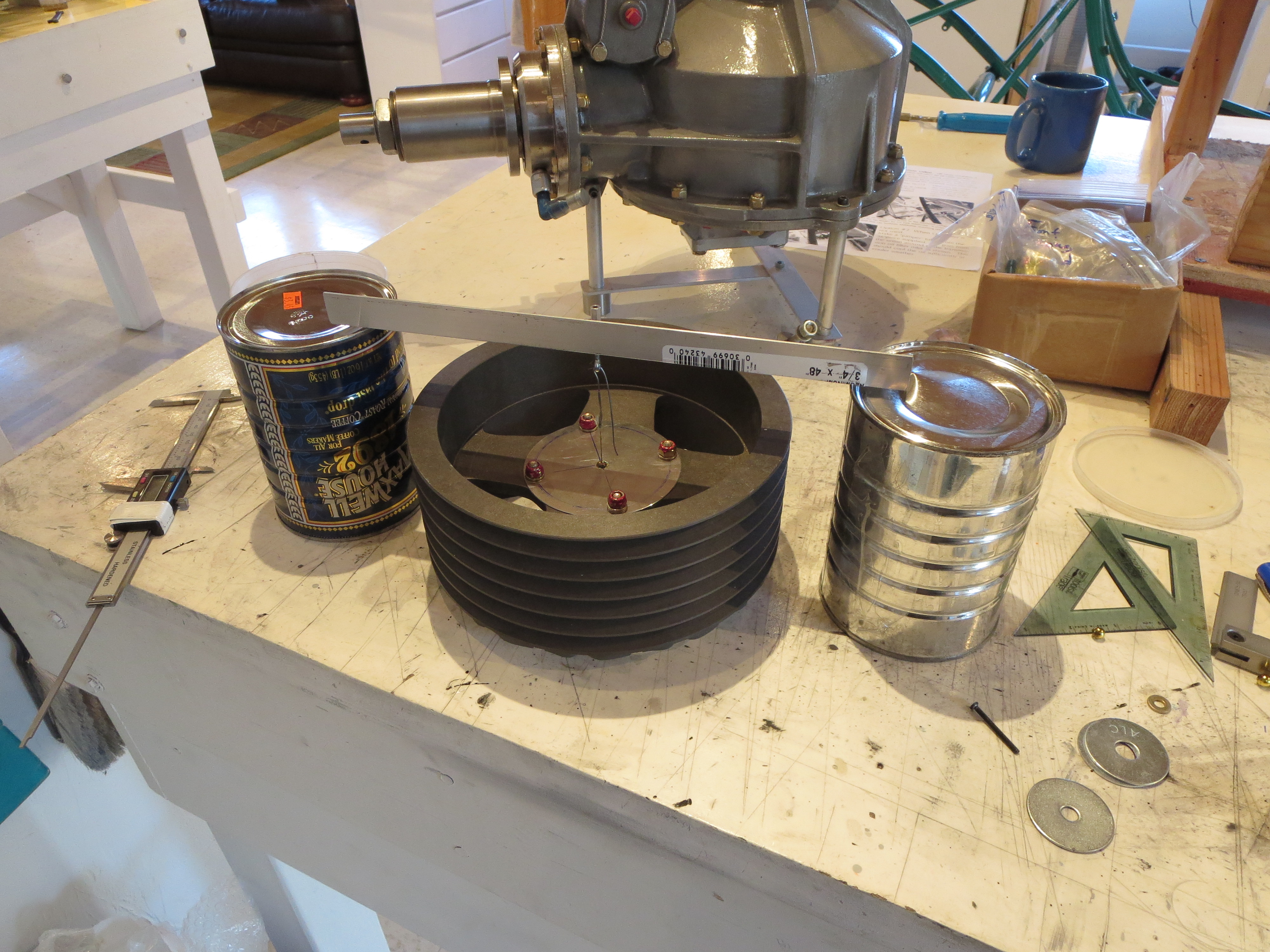
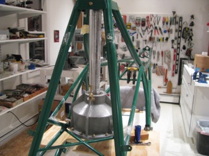
So I built a balancing jig. It's sized for the main transmission pulley and pretty basic. Some heavy stock for the sides and base and two sections of stainless steel ruler (Harbor Freight $1 items) for the "knife edges" sanded and polished on the edges.
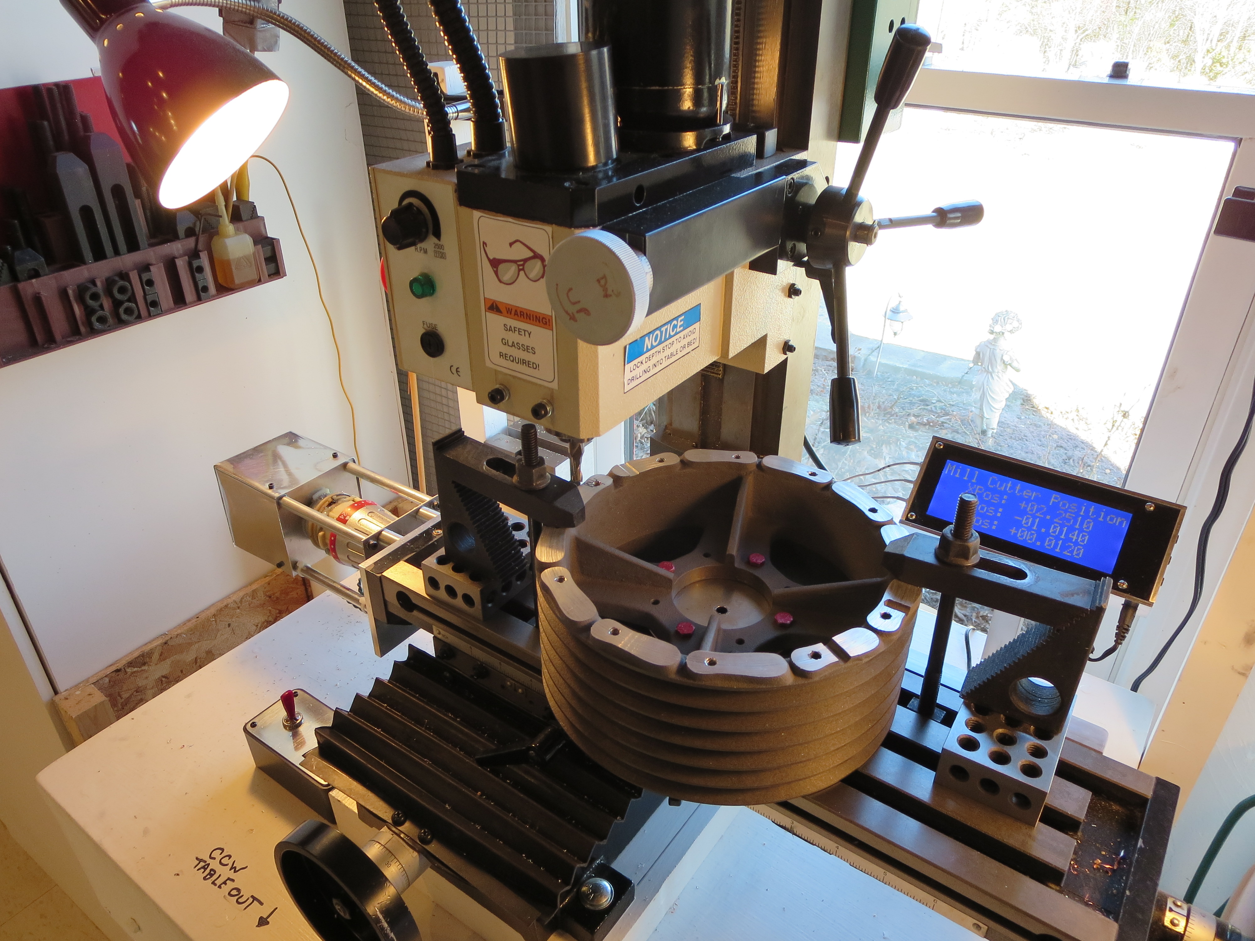
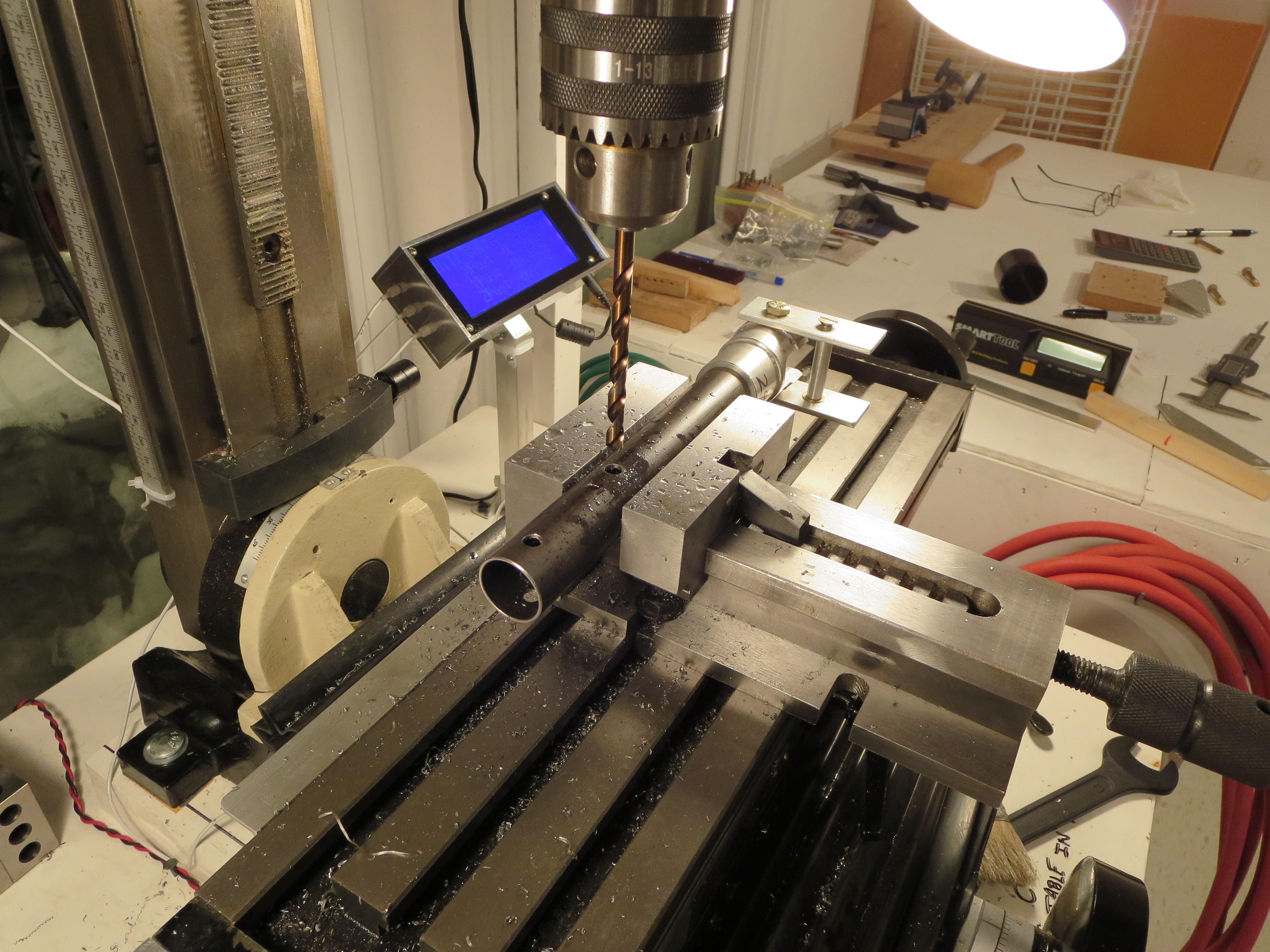
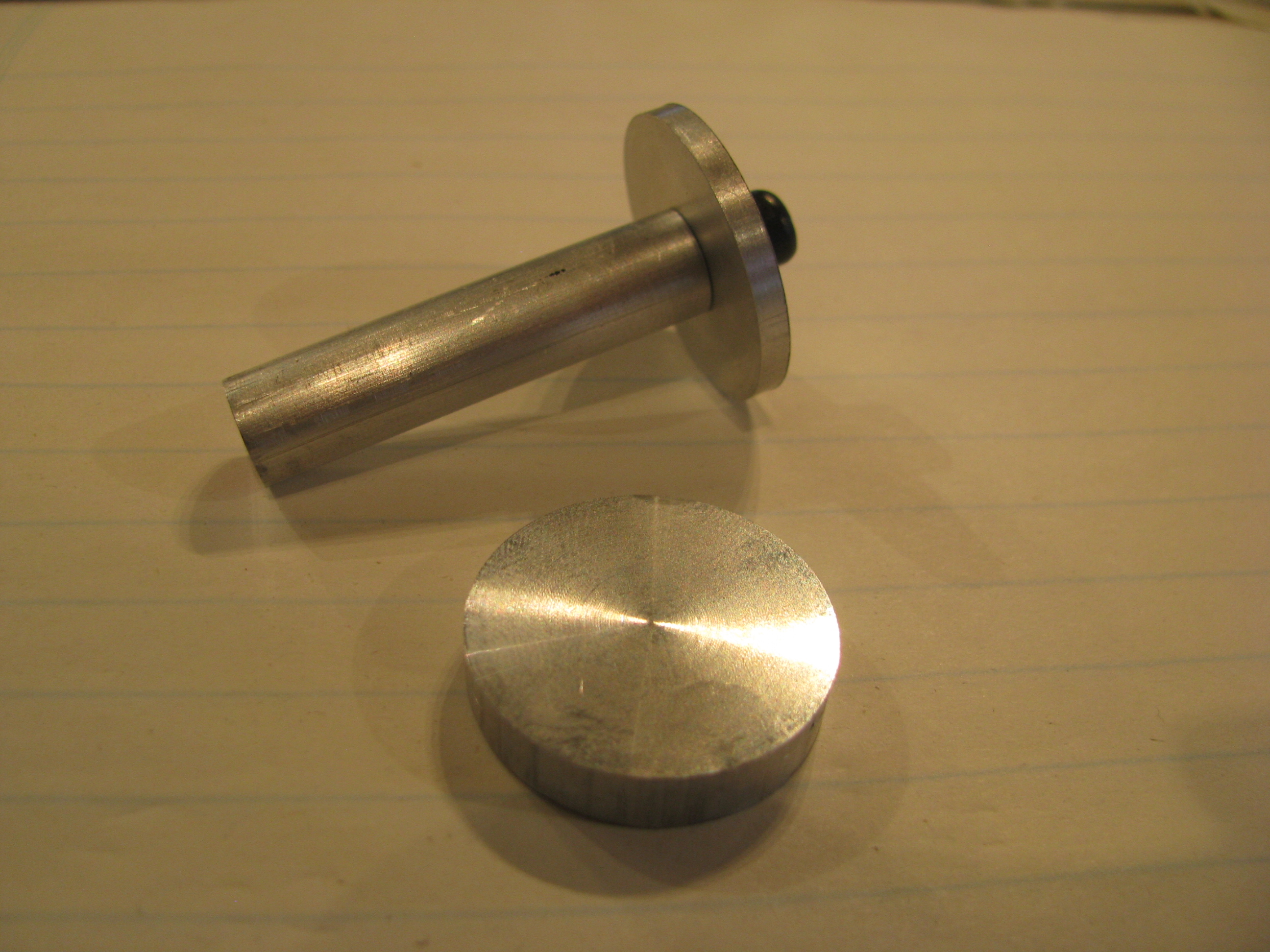
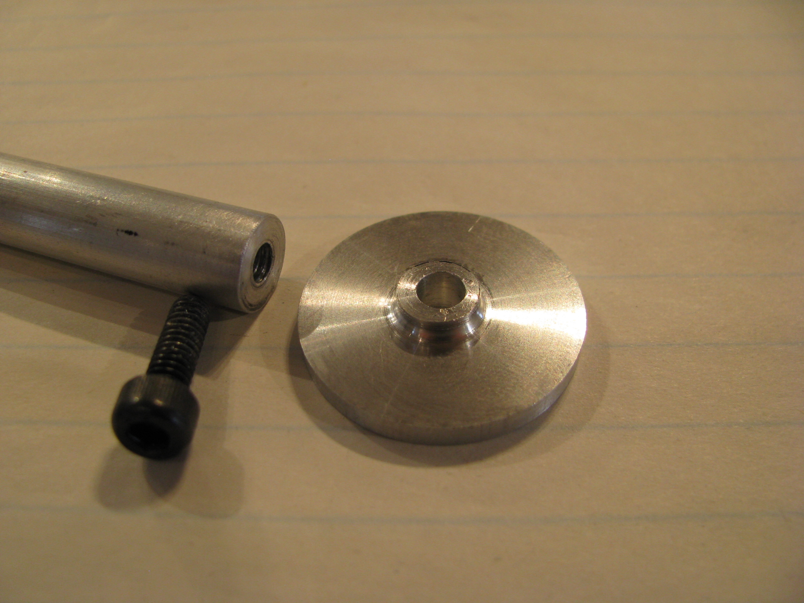
The carrier is an "almost" square block. I measured and drilled the bolt holes for the pulley flat face as precisely as I could (again, the mill with DROs is a godsend). All holes are +/- 0.002" of their ideal position. The center spindle is a piece of 4130 steel tubing. I drilled the center hole slightly undersized and sanded up to a super snug press fit. Once pressed in the tubes were sanded and polished.
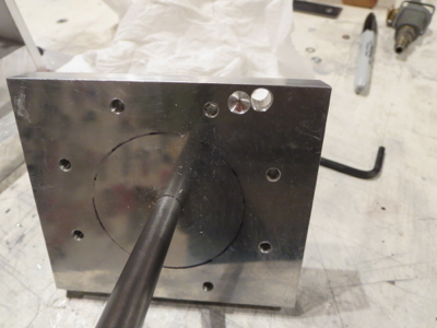
Next, the carrier assembly itself has to be balanced as perfectly as possible and the jig leveled. The through hole and the partially drilled hole achieved that balance. There were already some partially drilled holes on the other side of this block, and the drilling ops are not perfect, no matter how carefulIy it was machined. This is a very important step. When the carrier spindle is balanced you can level the jig with shims to be perfectly level. Even the tiniest of differences causes the balanced item to roll off one side or the other. It's pretty impressive how delicate/accurate this thing is.

Only THEN can you start balancing the pulley. Bolt it together, see which side is down, mark it, redo the measurement with the carrier at 4 90 degree points, then draw lines across the face of the pulley. The center intersection point is the center of gravity. Since the carrier is not perfectly centering, you must do four measurements at the cardinal points and then draw the centroid. Only THEN remove material on the heavy side - a little at a time - then repeat.
It took several hours, but I am quite satisfied that the balance is WAY better than anything achieved taking the pulley right out of the box, especially if you bolted those hand-cut cooling fins on. I am pretty sure it is now within a gram or two of perfect balance.
Bolted, torqued, and torque sealed in the ship for the last time! Another "final assembly" thing down. On to the engine!

So I built a balancing jig. It's sized for the main transmission pulley and pretty basic. Some heavy stock for the sides and base and two sections of stainless steel ruler (Harbor Freight $1 items) for the "knife edges" sanded and polished on the edges.
The carrier is an "almost" square block. I measured and drilled the bolt holes for the pulley flat face as precisely as I could (again, the mill with DROs is a godsend). All holes are +/- 0.002" of their ideal position. The center spindle is a piece of 4130 steel tubing. I drilled the center hole slightly undersized and sanded up to a super snug press fit. Once pressed in the tubes were sanded and polished.
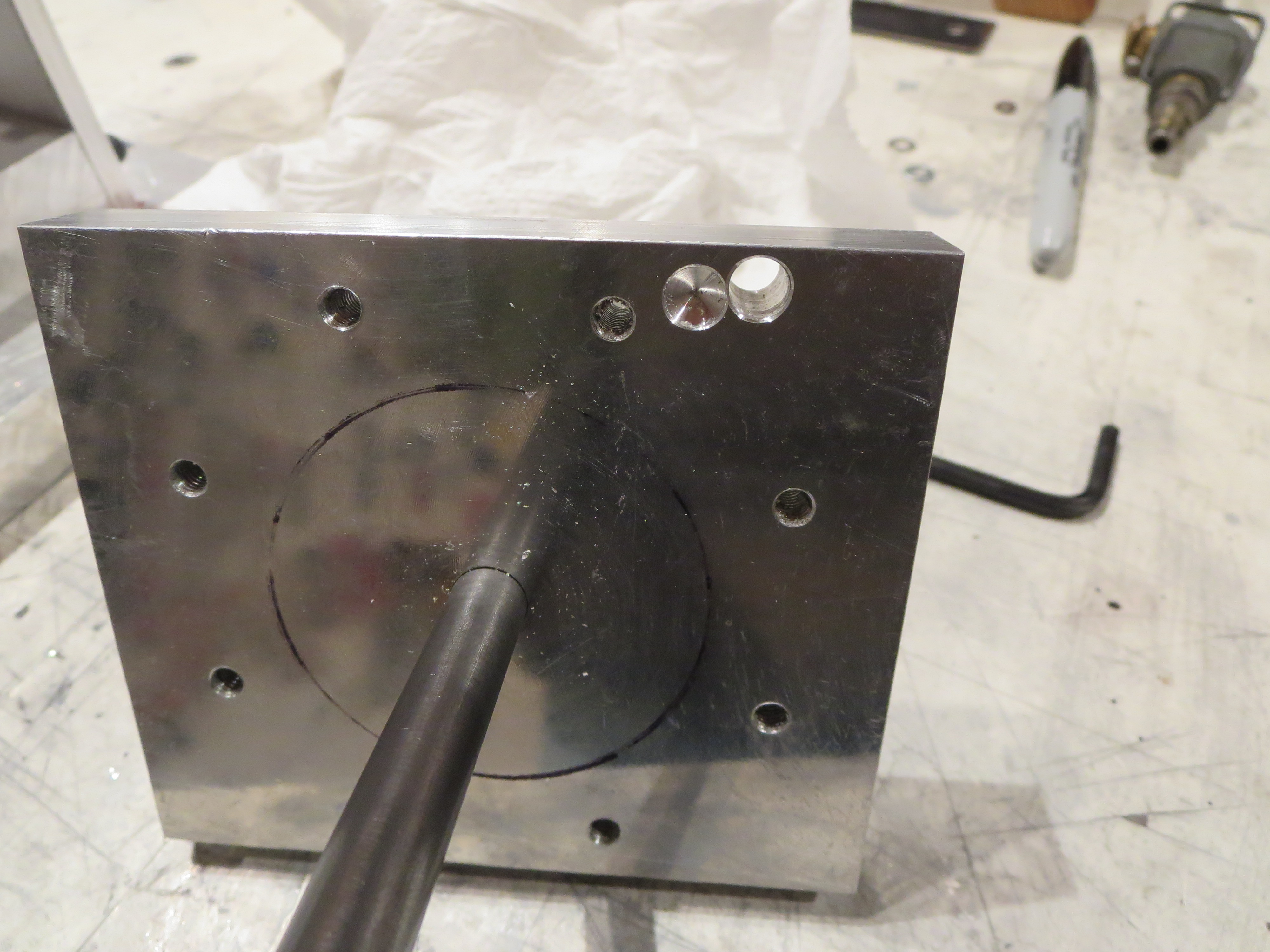
Next, the carrier assembly itself has to be balanced as perfectly as possible and the jig leveled. The through hole and the partially drilled hole achieved that balance. There were already some partially drilled holes on the other side of this block, and the drilling ops are not perfect, no matter how carefulIy it was machined. This is a very important step. When the carrier spindle is balanced you can level the jig with shims to be perfectly level. Even the tiniest of differences causes the balanced item to roll off one side or the other. It's pretty impressive how delicate/accurate this thing is.
Only THEN can you start balancing the pulley. Bolt it together, see which side is down, mark it, redo the measurement with the carrier at 4 90 degree points, then draw lines across the face of the pulley. The center intersection point is the center of gravity. Since the carrier is not perfectly centering, you must do four measurements at the cardinal points and then draw the centroid. Only THEN remove material on the heavy side - a little at a time - then repeat.
It took several hours, but I am quite satisfied that the balance is WAY better than anything achieved taking the pulley right out of the box, especially if you bolted those hand-cut cooling fins on. I am pretty sure it is now within a gram or two of perfect balance.

Bolted, torqued, and torque sealed in the ship for the last time! Another "final assembly" thing down. On to the engine!
Oil Cooler Endcaps
07/18/14 13:06 Filed in: All
Of course now that I have this groovy router/engraver every problem will have a routing/engraving component to it. It is pretty cool to have something that can add detailed and permanent markings.
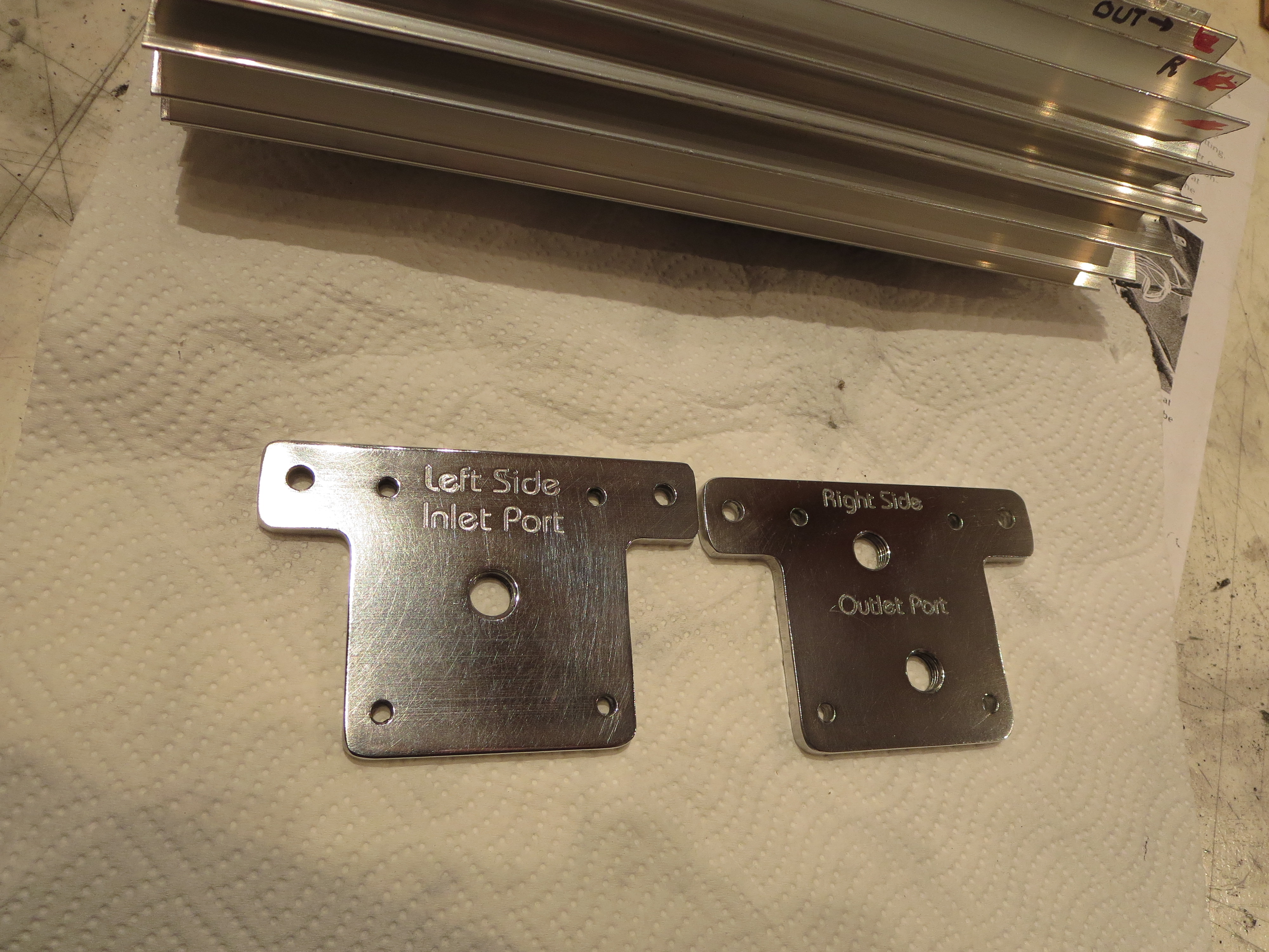
Here are the end caps to the Hap Miller supplied oil cooler. This labeling is not strictly necessary, but a start.
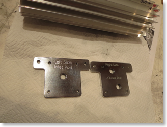 I am definitely learning what works and how to work the machine. I engraved too deeply initially and snapped the first engraving bit and had to restart. That's why the "L" and the "e" in "Left" are a little smeary; two passes at a one-step offset that probably happened when I changed the bit.
That's just a quick "shop polish". A camera angle that highlights the engraving also highlights the unpolished scratches in the aluminum. I am thinking I will just leave the oil cooler extrusion "natural clear anodized" and the end caps polished (more than this, though).
Here are the end caps to the Hap Miller supplied oil cooler. This labeling is not strictly necessary, but a start.
That's just a quick "shop polish". A camera angle that highlights the engraving also highlights the unpolished scratches in the aluminum. I am thinking I will just leave the oil cooler extrusion "natural clear anodized" and the end caps polished (more than this, though).
Main Shaft Plug
03/22/14 23:35 Filed in: All

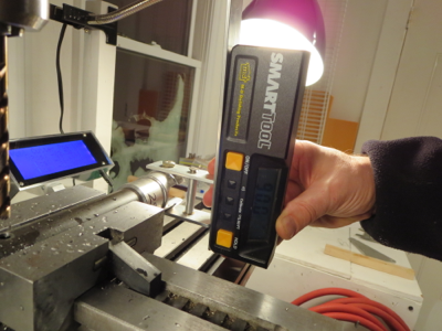
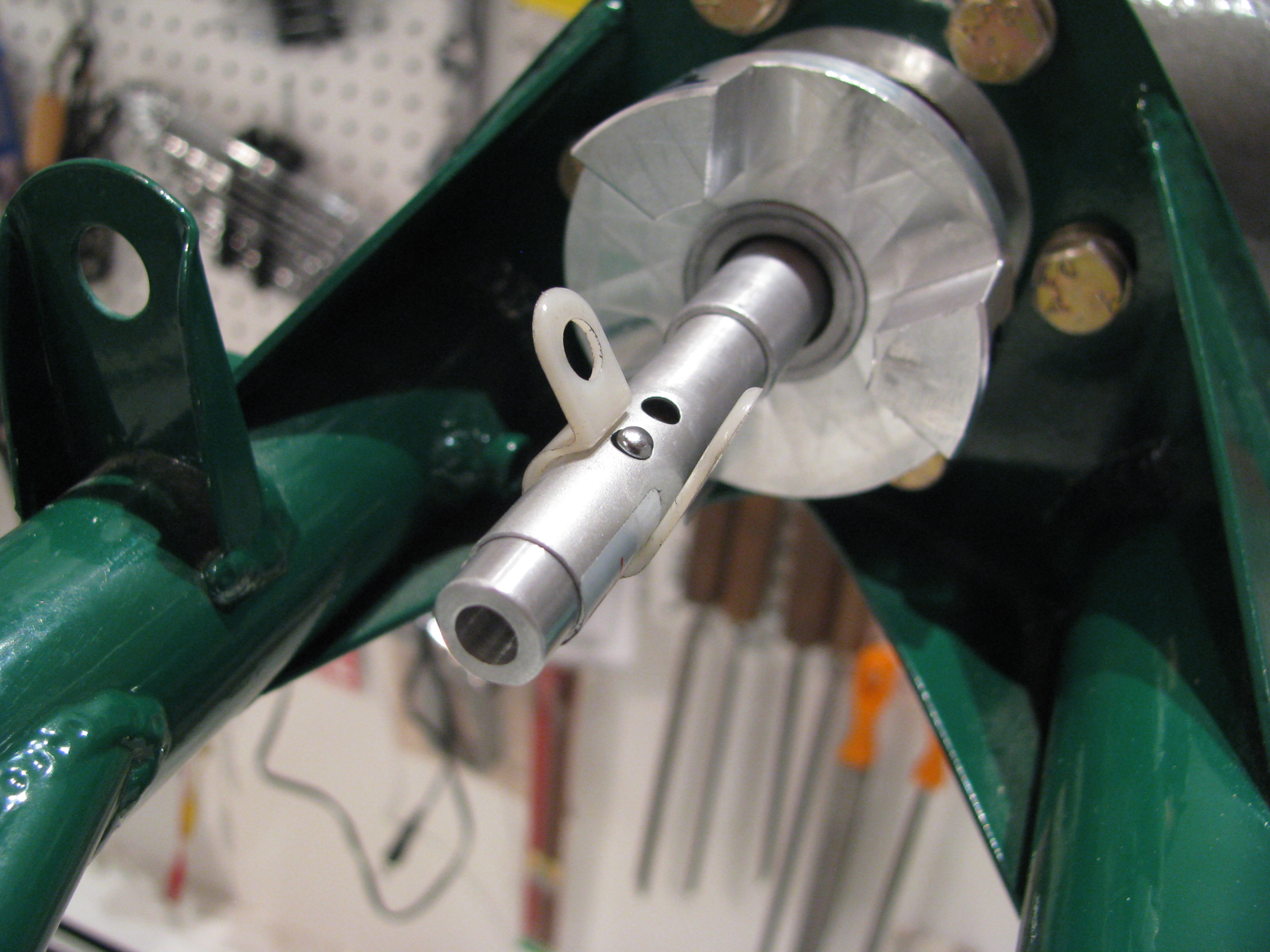
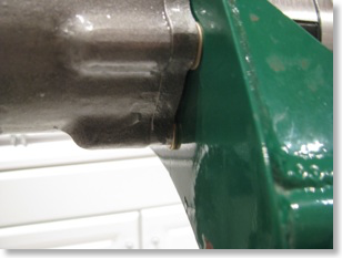
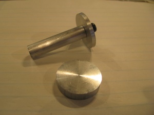
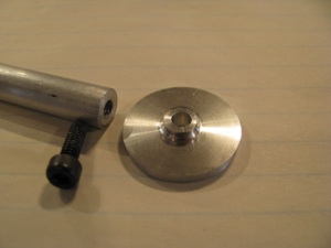
Well ahead of the transmission installation video in the rotor head video, BJ mentions how the main shaft should be plugged to keep out moisture. First up was to slather a goodly amount of Corrosion-X in the shaft after a few acetone swipes. Then I lathed up an ABS plug that was snug, but not even really "tap tight". Once parted the plug is only about an inch long.
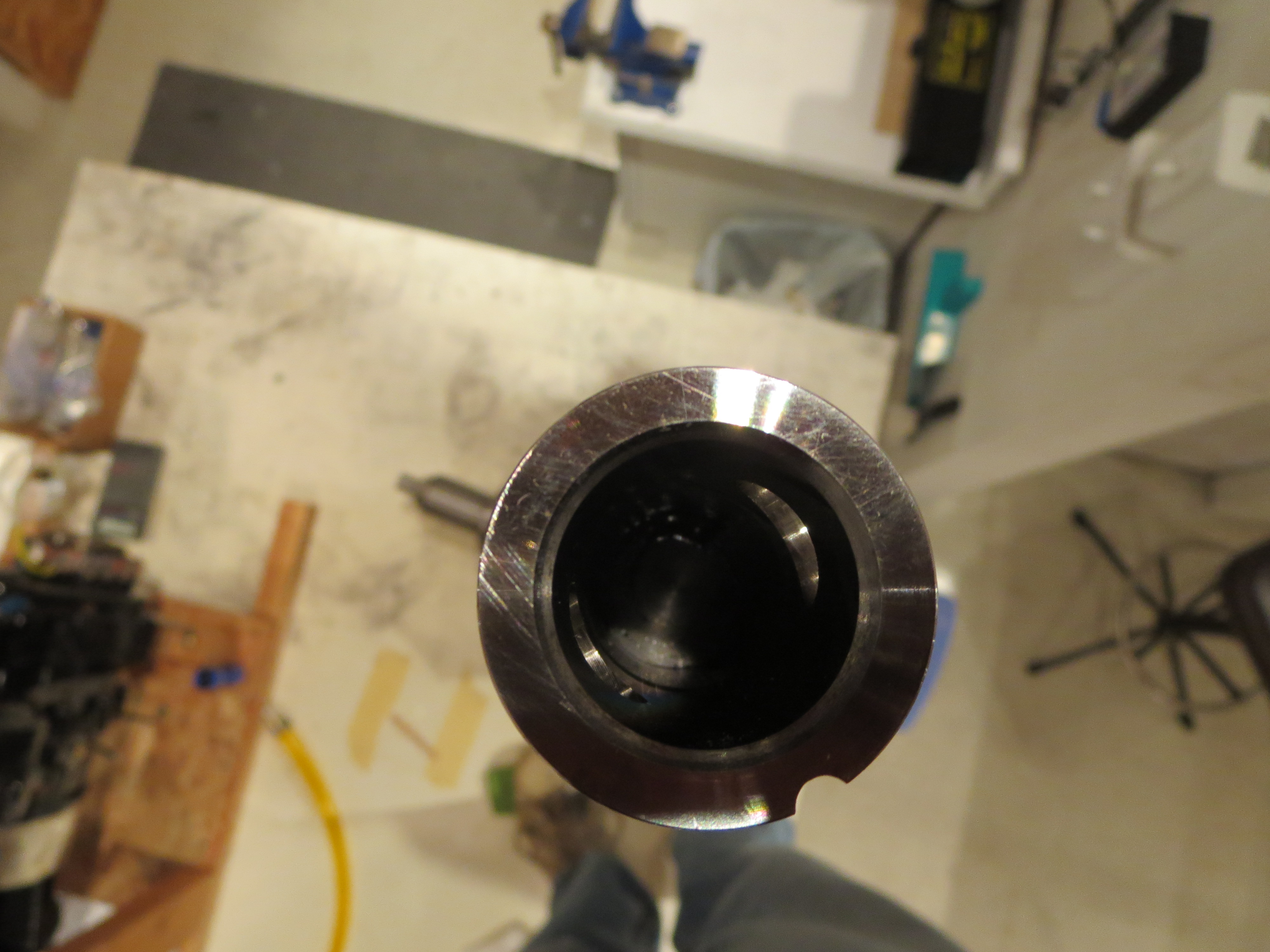
The plug was coated with 5-minute epoxy and slid down inside the tube. I measured the steel main drive plug that slides inside the shaft, then I pushed the moisture plug down plenty far enough to clear the plug when it is installed. While the epoxy was setting up I wiped and cleansed the inside of the tube above the plug with acetone to remove any trace of the epoxy so the drive plug will not be fouled when it is inserted.
The edges of the hole for the drive pin are sharp, sharp, sharp, and I cut the hell out of my finger while swabbing out epoxy. Nice mixture of acetone and epoxy now coursing through my bloodstream. About every two weeks I will cut a finger, grind myself or otherwise accumulate minor scar tissue on this project.
Rebalancing the Pulley
03/16/14 22:52 Filed in: All
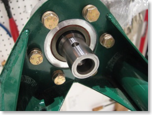
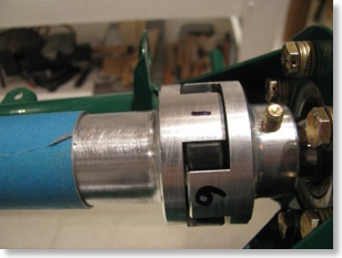
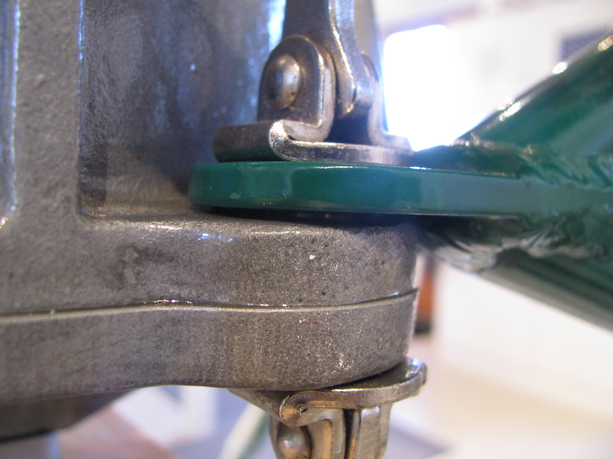
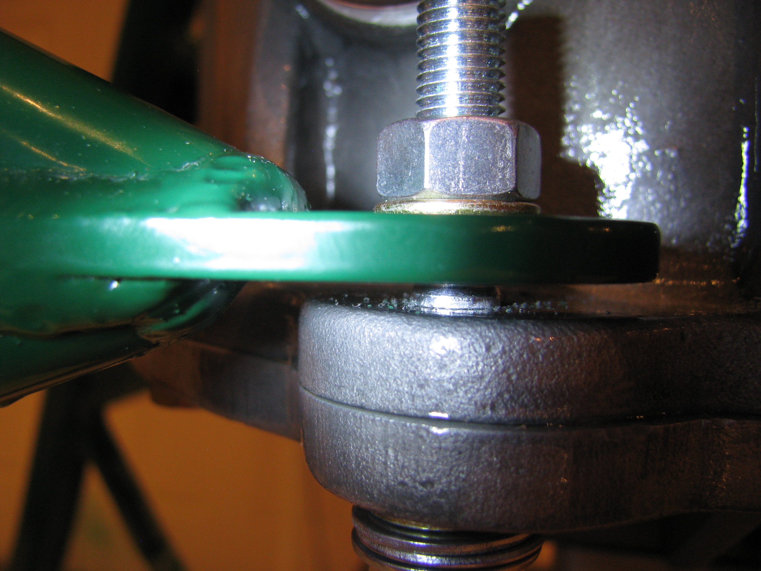
I did my best to rebalance the pulley. It really didn't seem that far off. I made a holder plate and a filament hanger. There was a slight offset that was corrected by a little milling. This setup is not precise enough to go much farther.
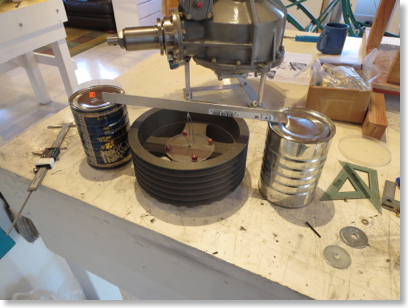

The locations that needed milling were on the side opposite the holes that had been drilled. This kind of makes sense if the holes were drilled to compensate for differences in the mass of the bosses that were milled off.
The locations that needed milling were on the side opposite the holes that had been drilled. This kind of makes sense if the holes were drilled to compensate for differences in the mass of the bosses that were milled off.
Transmission Final Prep
03/15/14 00:53 Filed in: All
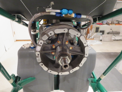
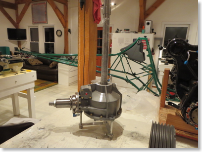
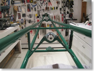
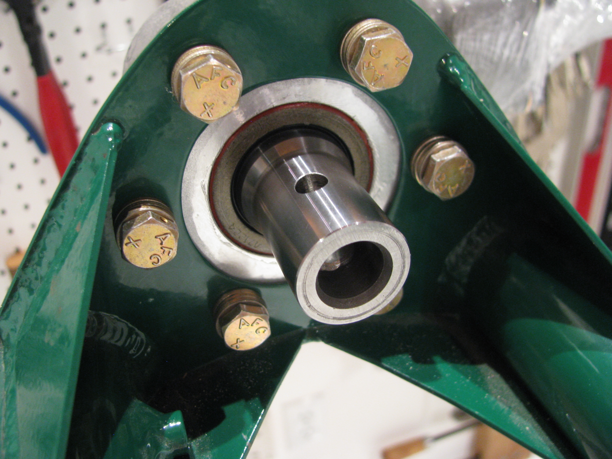
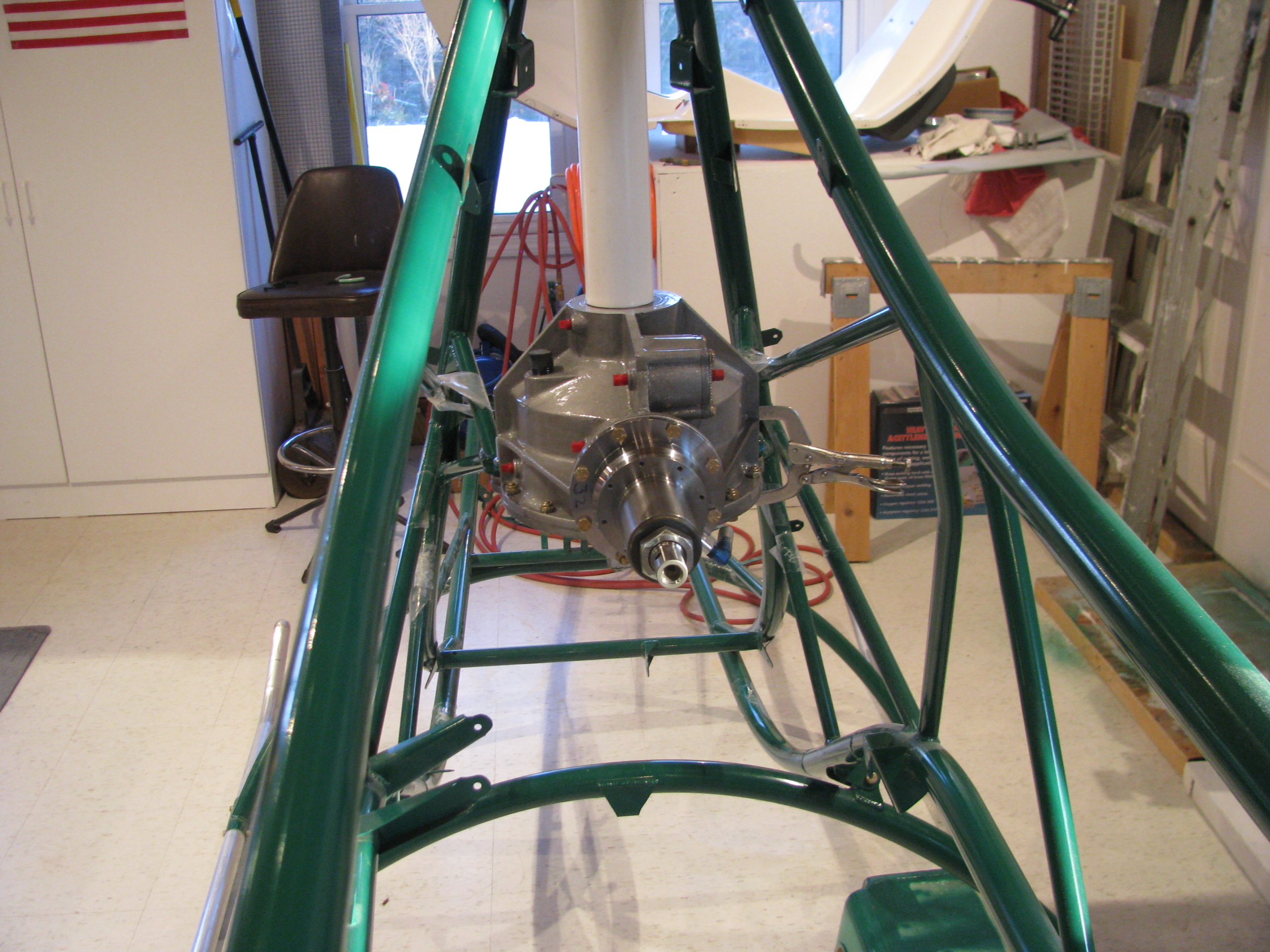
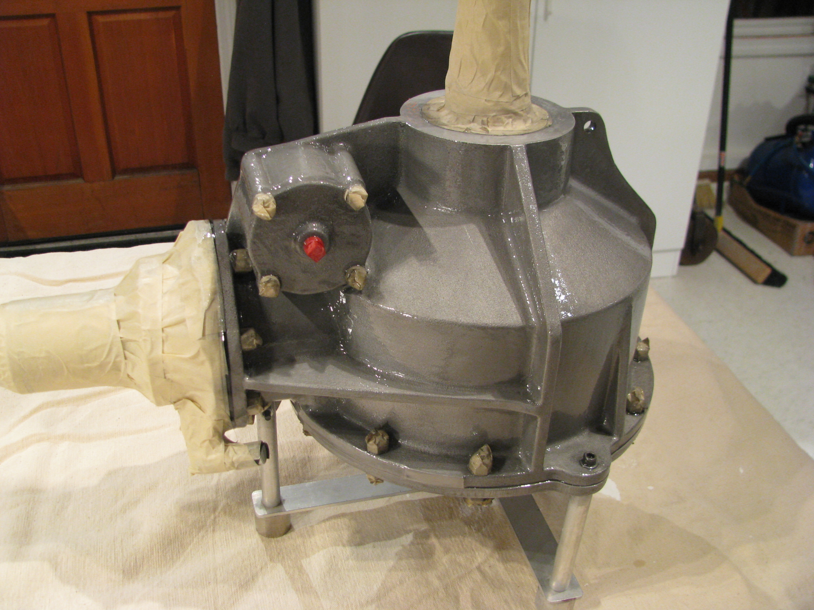
Pulled out the main transmission for last prep prior to final installation.
Now I have to dig out my references on how to re-install the plumbing.
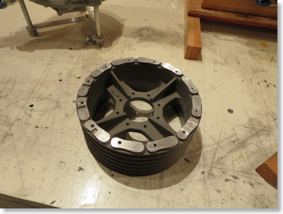
Since I am not planning on installing the fiberglass fan blades the bosses cast onto the pulley are just dead weight, so I chucked up the main pulley in my lathe and shaved them down. Any extra room in the pulley bay will be welcome I am sure. I left a little meat on the pads from the bosses to give me something to mill off in case there is some balancing to be done. You can see the remains of a couple of leftover holes that must have been drilled for balancing purposes back at the factory. I will admit that I did not notice those balancing holes until I started cutting and now will have to rig some sort of jig to allow for redoing the balance.
This is the largest thing I have ever worked with in my lathe and it was clearly operating at capacity.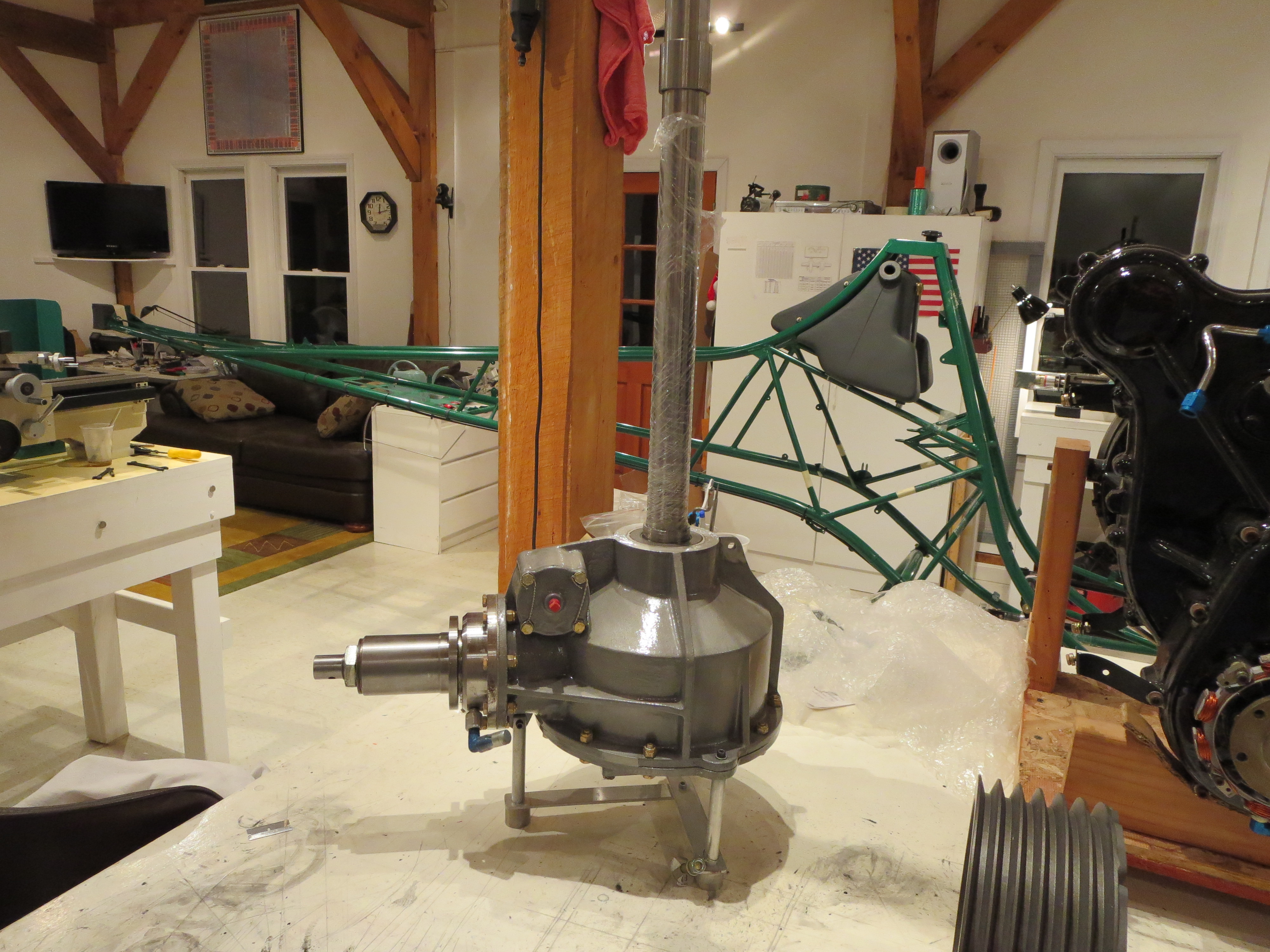
Clutch Final Assembled
03/03/14 00:38 Filed in: All
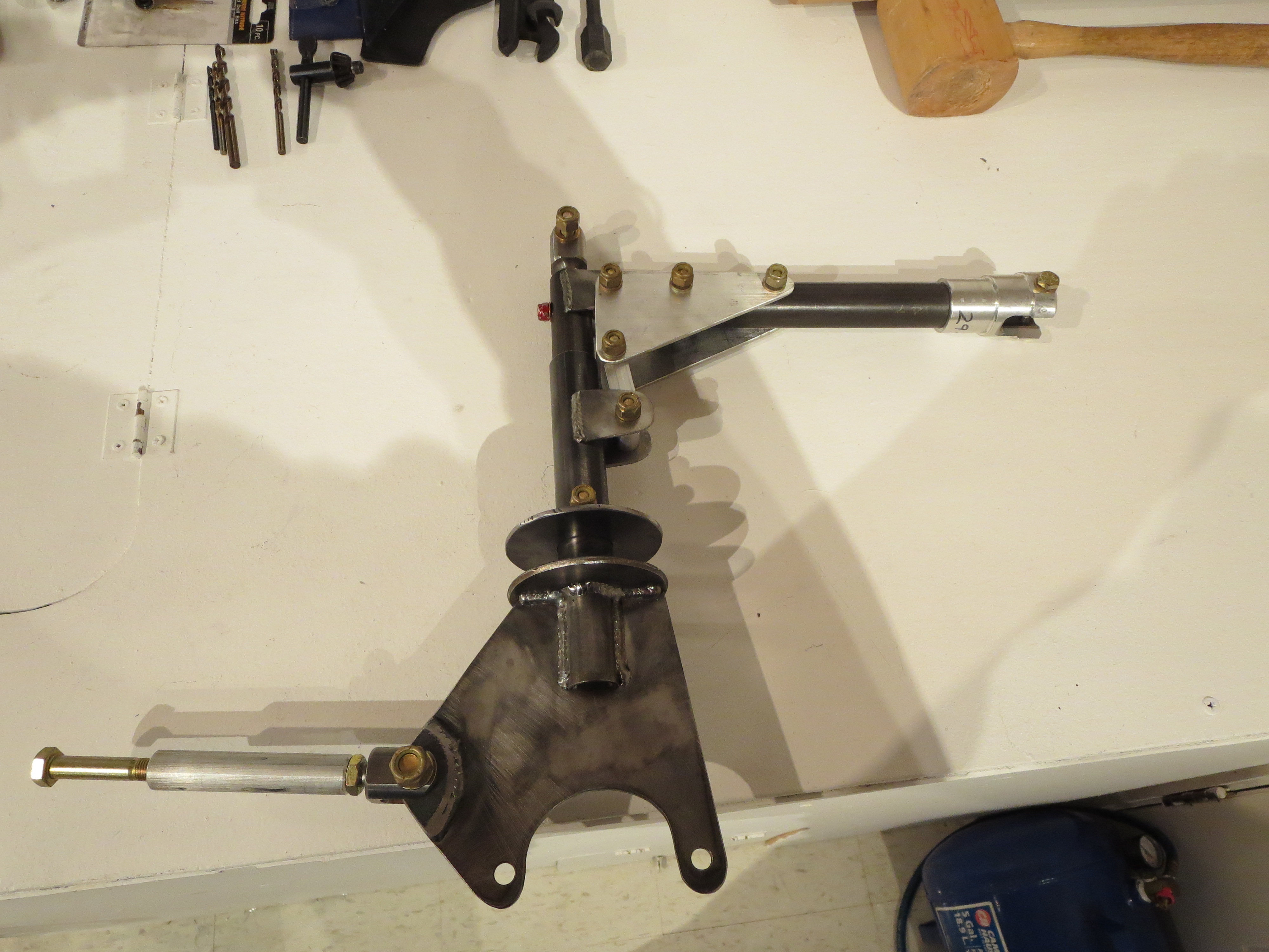
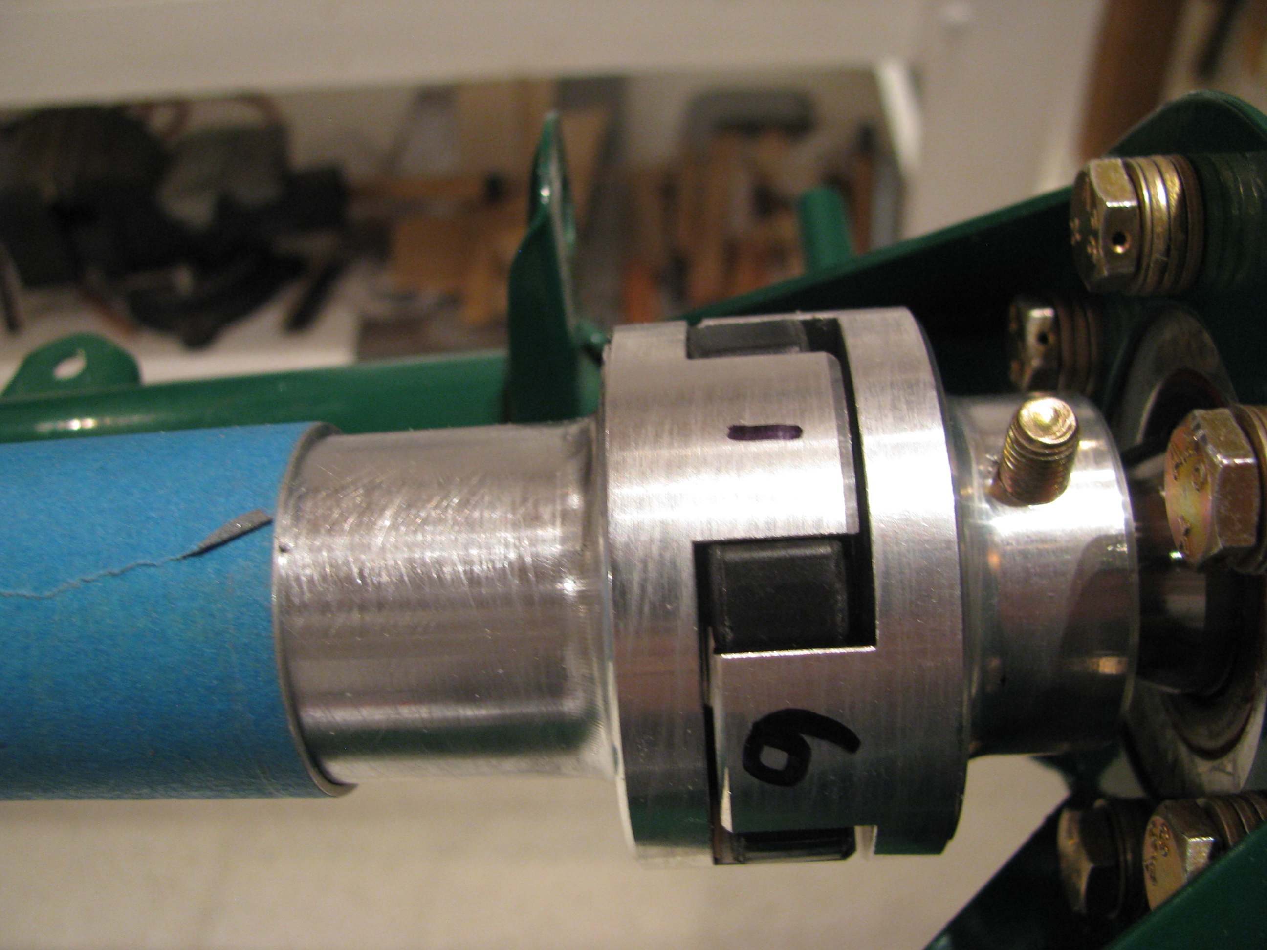
Painted and final assembled the clutch.

I used the Hap Miller compression disk instead of the stock rubber biscuit. Looks nicer and should be more stable. The bolts holding the angle plates are only bolted through the tubes, so the bolts can't really be torqued to spec (60 in-lb) without deforming the tubes, so torque was lowered a bit. All bolts were Loctited and all sliding surfaces were greased prior to final assembly.
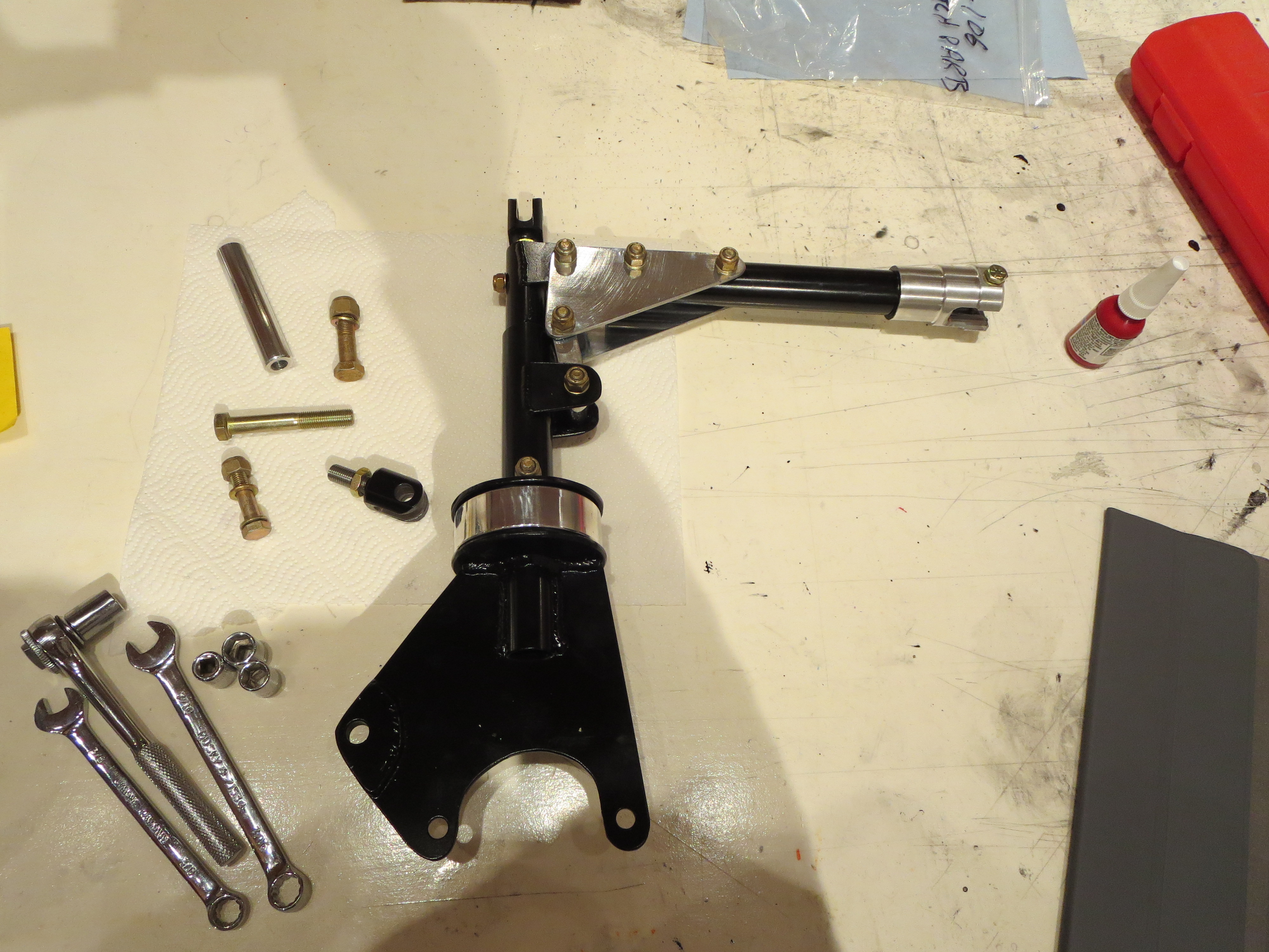
I used the Hap Miller compression disk instead of the stock rubber biscuit. Looks nicer and should be more stable. The bolts holding the angle plates are only bolted through the tubes, so the bolts can't really be torqued to spec (60 in-lb) without deforming the tubes, so torque was lowered a bit. All bolts were Loctited and all sliding surfaces were greased prior to final assembly.
Mixer Assembled
02/28/14 00:14 Filed in: All
Finished up assembly of the mixer.

This is so much nicer than the original item. It looks and feels like a quality item.
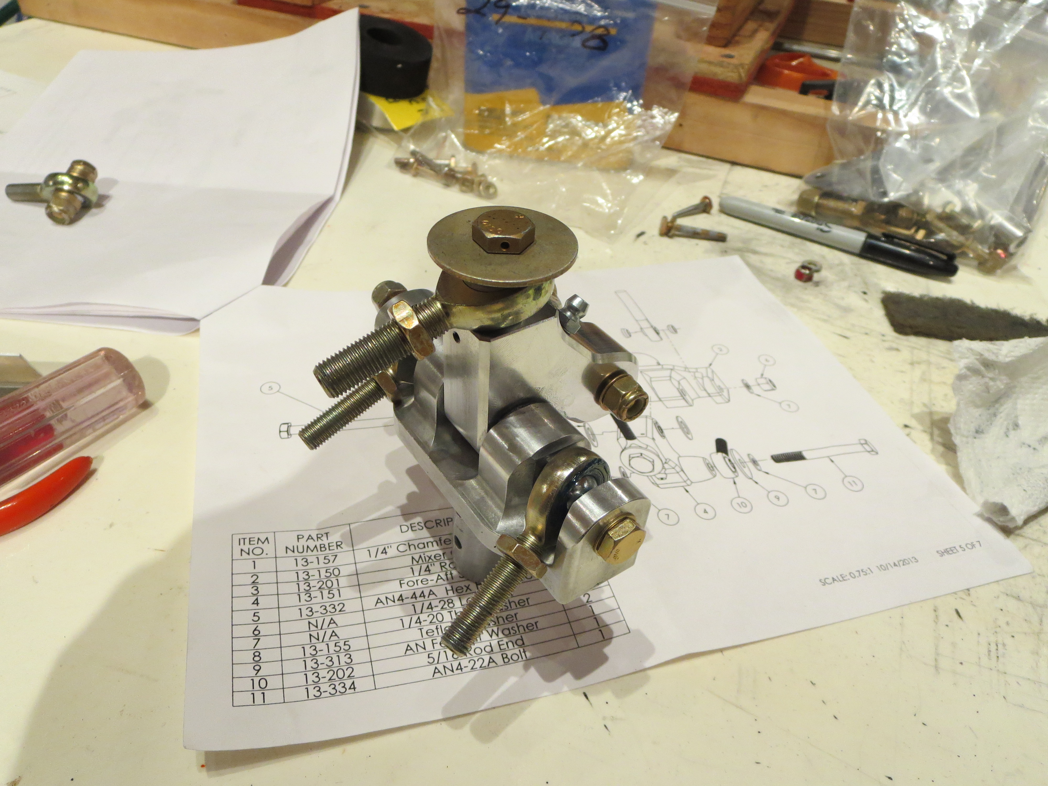
This is so much nicer than the original item. It looks and feels like a quality item.
Clutch Pre-Assembly
02/17/14 23:58 Filed in: All
The clutch is pretty basic. First, install a threaded steel plug in the top piece and cross drill for a bolt. I don't have picture, but found a little trick. BJ says to use a vice or a press to jam in the plug. I looked down the tube and plug with a small flashlight shining UP through the tube. It could be seen that the steel tube was slightly out of round (probably from the welding). Well, just give a light squeeze in a vice to the tube on the wide sides and the plug just tap, taps in with a little piece of wood - actually very gently. No ham-handed vice-pressing needed.

Next up is drilling the side plates to the clutch lever arm. I made use of my jig plates (from the cyclic tube mixer mount operation) to get a perfect alignment between the bolts and the holes for the plates.
Jig plates repurposed and alignment exact. It pays to make sure that mill is perfectly level and mill head is trammed. Then everything can be referenced to 0.0 degrees or 90.0 degrees.
It seems like a pain to make little jig thingies for a single operation, but I usually can find a secondary purpose for them which make the time spent much more worthwhile.

Complete clutch assembly pre-fitted (except rubber parts and bearing). Now I just have to tidy up the steel parts (they picked up some scale having sat for so long), prime, and paint. With the precision of the mill, and no broken drill bits, the pieces just fall together, snug and true. The clutch is a very simple assembly project.
Next up is drilling the side plates to the clutch lever arm. I made use of my jig plates (from the cyclic tube mixer mount operation) to get a perfect alignment between the bolts and the holes for the plates.

Jig plates repurposed and alignment exact. It pays to make sure that mill is perfectly level and mill head is trammed. Then everything can be referenced to 0.0 degrees or 90.0 degrees.
It seems like a pain to make little jig thingies for a single operation, but I usually can find a secondary purpose for them which make the time spent much more worthwhile.
Complete clutch assembly pre-fitted (except rubber parts and bearing). Now I just have to tidy up the steel parts (they picked up some scale having sat for so long), prime, and paint. With the precision of the mill, and no broken drill bits, the pieces just fall together, snug and true. The clutch is a very simple assembly project.
Hap Miller Bits
11/11/13 21:45 Filed in: All
I ordered a bunch of bits and pieces from Hap Miller. Earlier I ordered and received his machined lift strut and it was of very good quality, so I wanted to see what else he has. Turs out a lot.
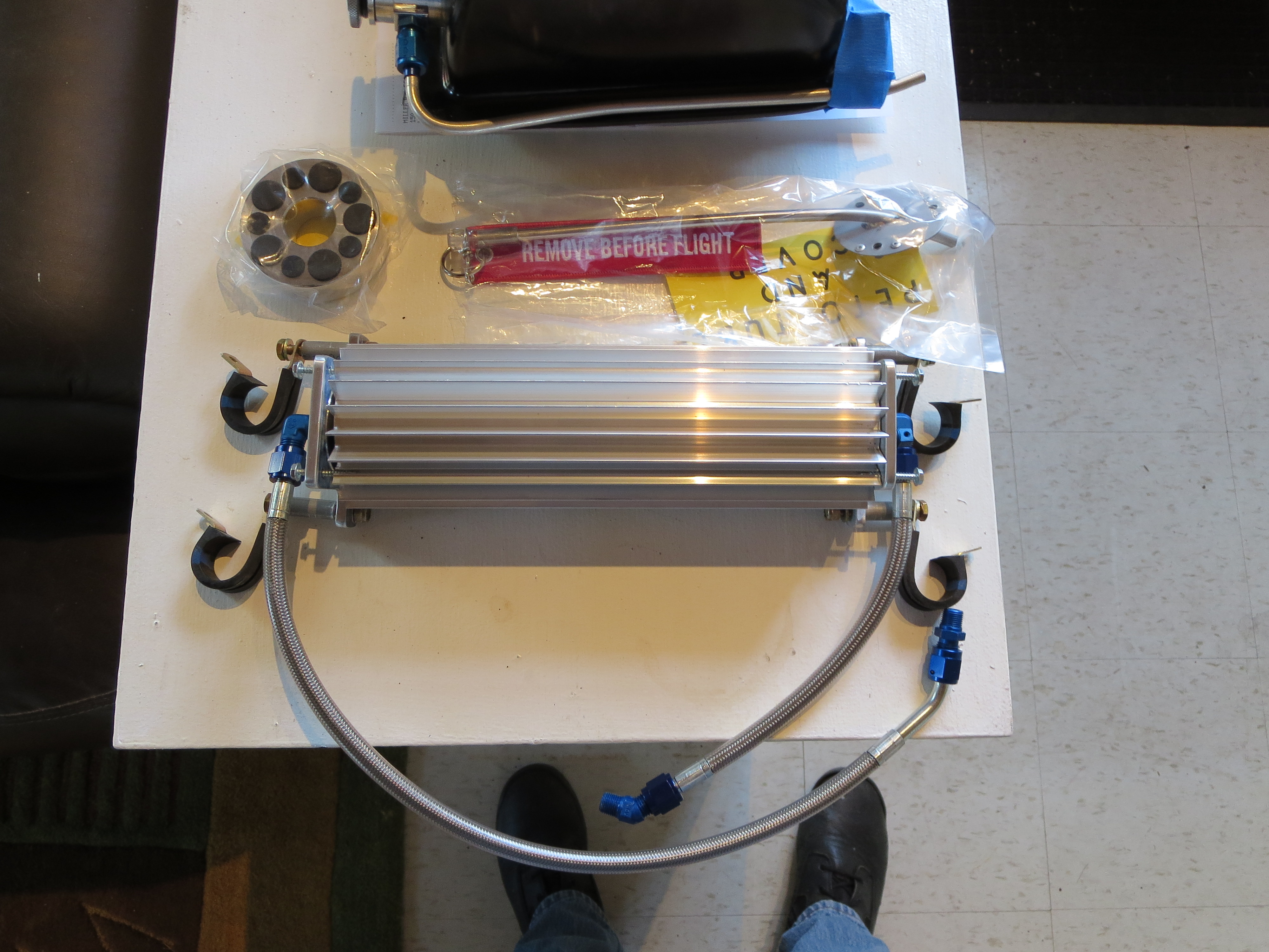
Here is the transmission oil cooler, clutch disk, and welded pitot tube. Nice!
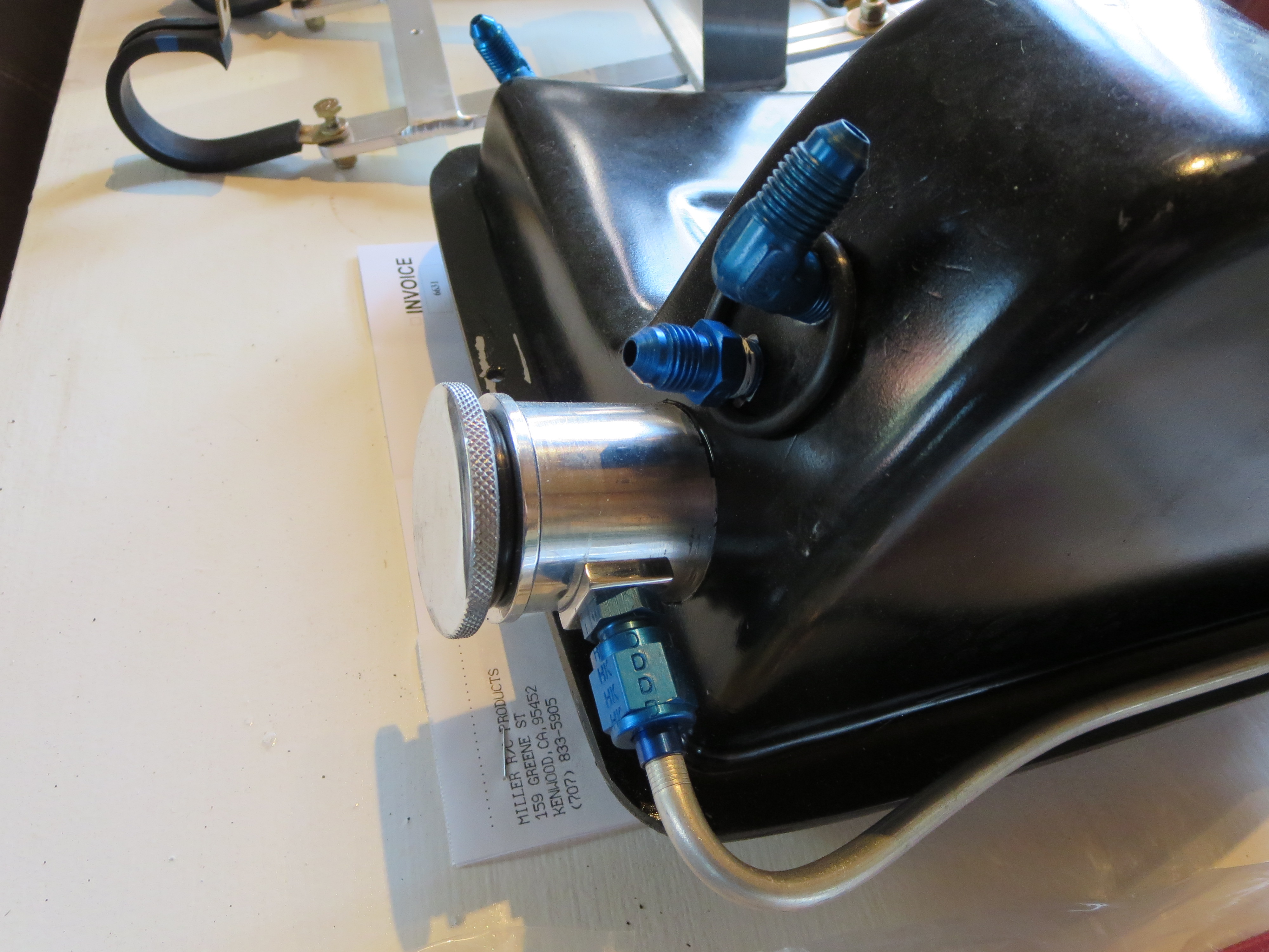
Hap claims that the "T" on the oil return to the tank actually impeded the return oil flow, so he recommends second fitting to return the oil independently and will add one to your tank. He also has a nice machined cap with integral dipstick.
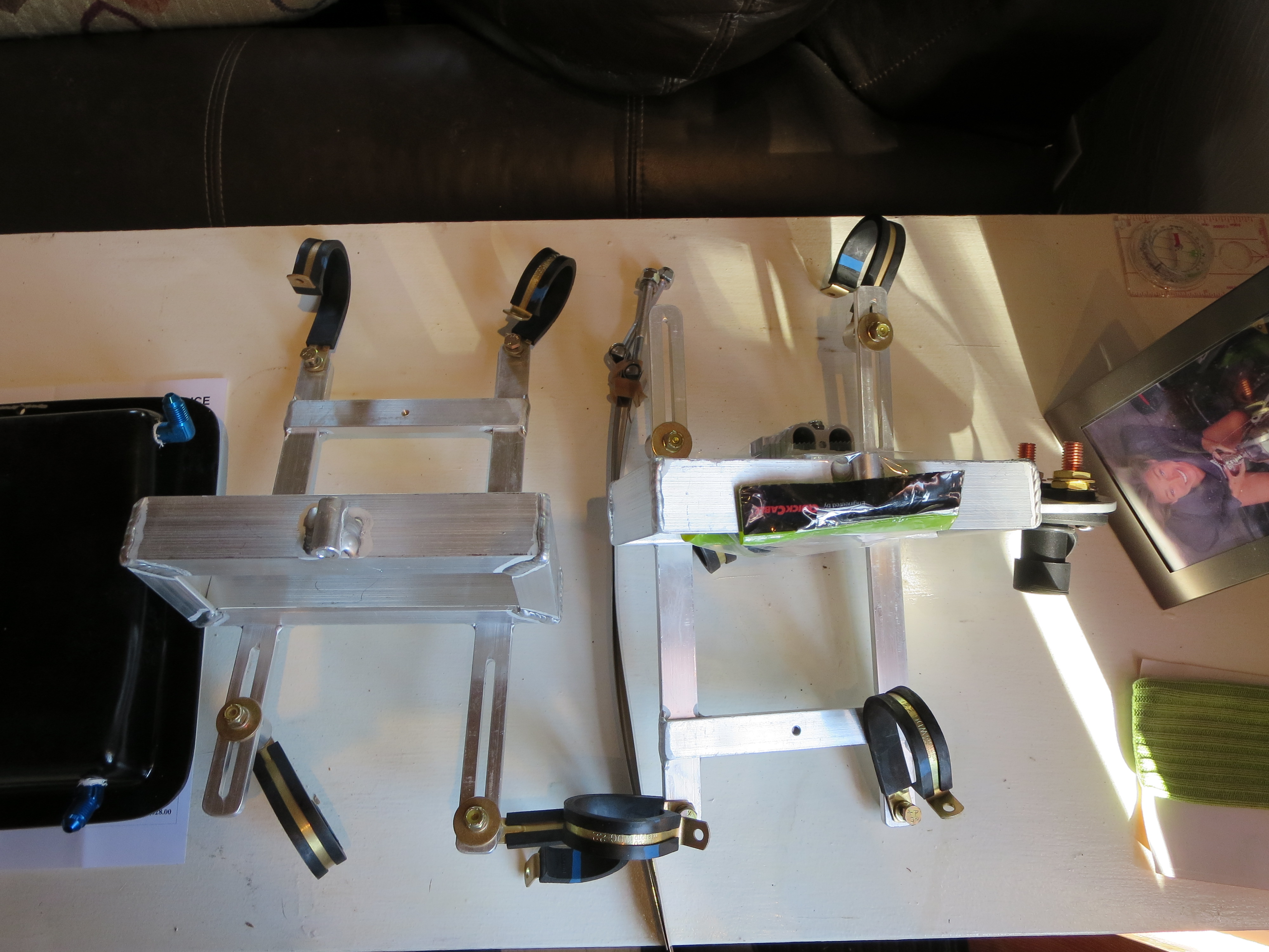
Lastly are the battery boxes. These mount just behind the transmission and accommodate a pair of Odyssey PC680 batteries. Nice aluminum welding work. It will be a shame to paint them and cover up those nice beads.
Machining Shaft Dogs
07/15/12 11:44 Filed in: All
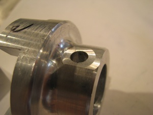
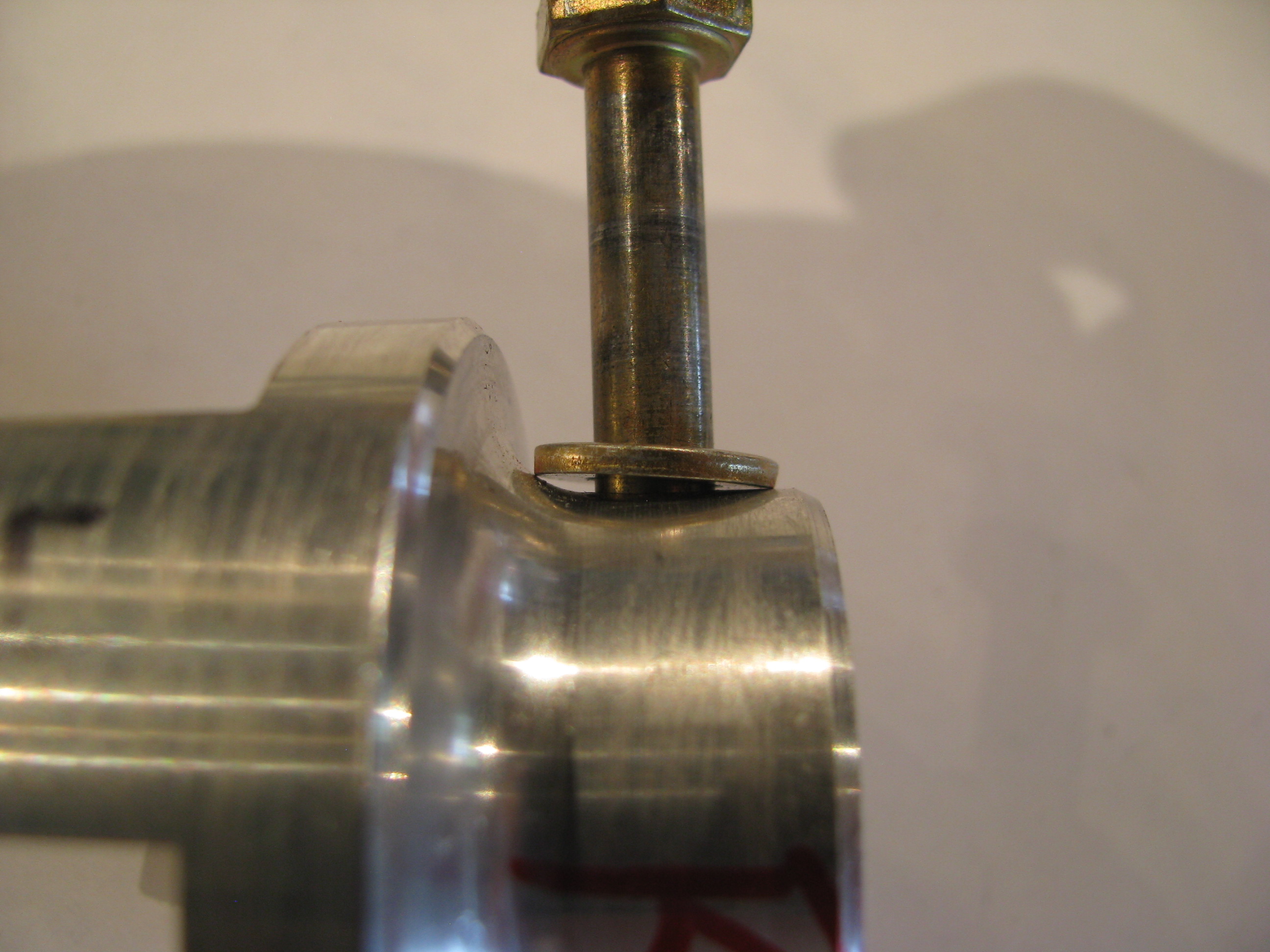
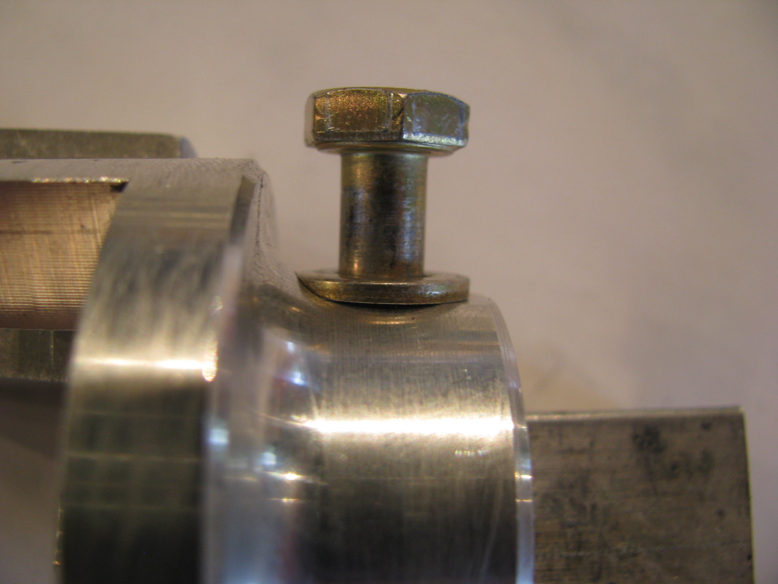
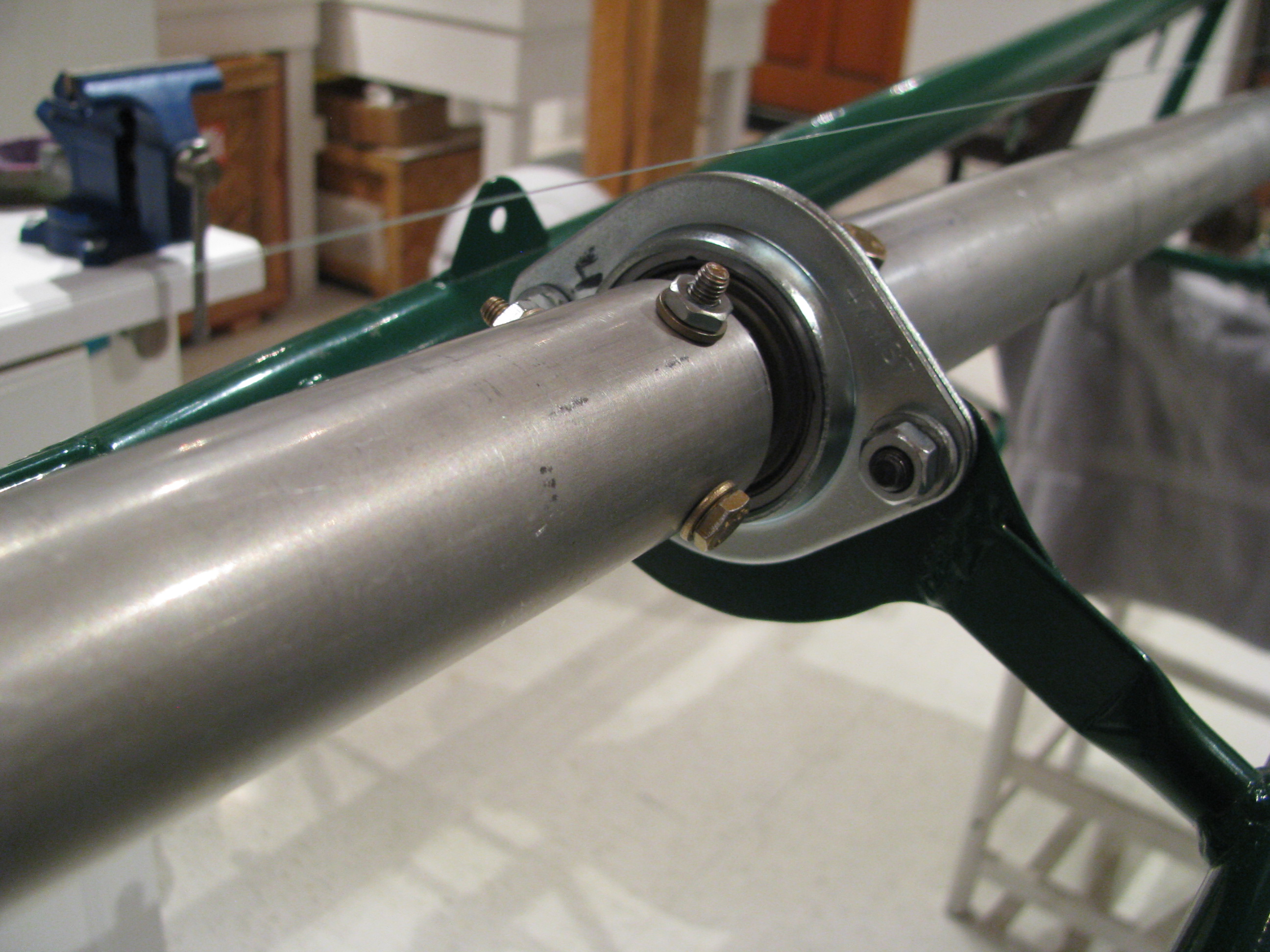
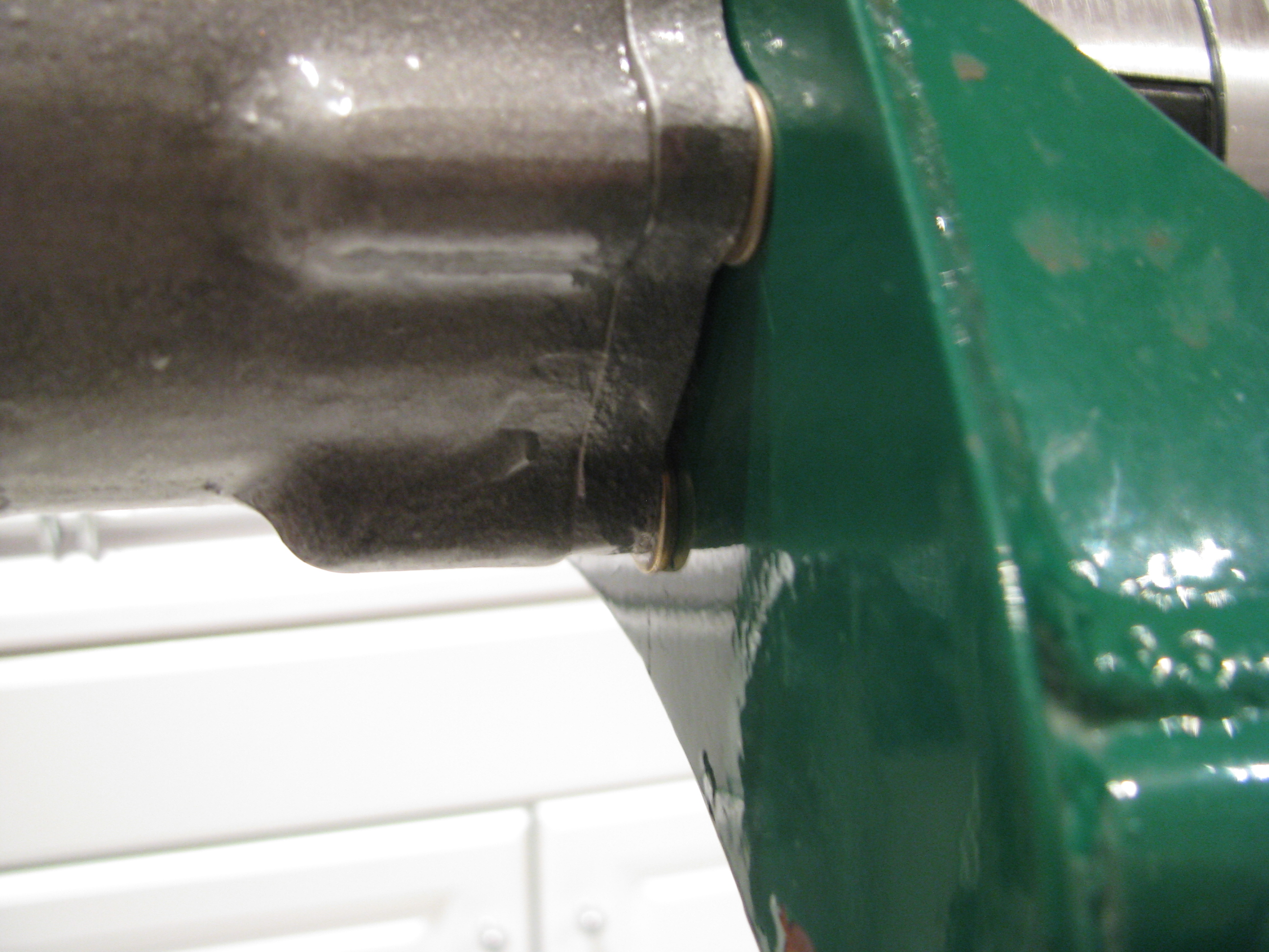
One of the little tasks I had pending was to clean up the bolt seats on the tail rotor drive shaft dogs.
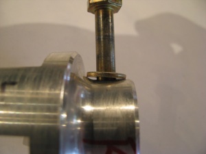
Because of the curved taper from the shaft collar to the dog face, the washer/bolt interferes with the curve.
I could have filed an angle on the washers, but that seemed a little inelegant, and I DO have this wonderful mill.

Like all the machining I have done, clamping aligning and measuring is 90% of the time and the actual metal cutting takes about 12 seconds.
I was careful to not take off very much. This is a jumbo-thick part, so I am sure it is plenty strong, but I still did not want to cut full width flats as that would have eaten quite a bit more metal.
Because of the curved taper from the shaft collar to the dog face, the washer/bolt interferes with the curve.

I could have filed an angle on the washers, but that seemed a little inelegant, and I DO have this wonderful mill.
Like all the machining I have done, clamping aligning and measuring is 90% of the time and the actual metal cutting takes about 12 seconds.
I was careful to not take off very much. This is a jumbo-thick part, so I am sure it is plenty strong, but I still did not want to cut full width flats as that would have eaten quite a bit more metal.
Bearing Block Mounting
03/12/12 11:42 Filed in: All
I have been poking along on a lot of different projects, but back to the tail rotor shaft. Each section is a little different. The following are the measurements I settled on TRShaftDims.pdf . The holes are all now drilled and I have put it all together and am starting the final alignment procedure.


Almost done with gearboxes. Starting to look into the tail rotor.
More Heli-nerd stuff: I put together the entire tail rotor driveshaft, aligned it, and re-measured the clearance between the mating drive dog faces. Two different feeler gauges were used with different combinations of fingers to average out the errors, In all cases each measurement agreed within 0.001” of each other
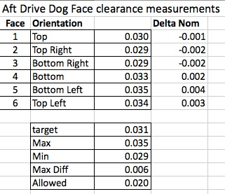
I am very pleased with the result at the rear. The shimming of the tail rotor gearbox is good and the drilling and fitting of the shafts didn’t change things that much. Cool. Everything is nicely centered on the nominal measurement and well under the allowed differential of 0.020”.
At the beginning of the video BJ gives you the target dimensions and at the end he sort of fudges and lets you know what you can really get away with. Happily I did not have to take advantage of the relaxed spec.
At the front shaft drive dog I got the following:
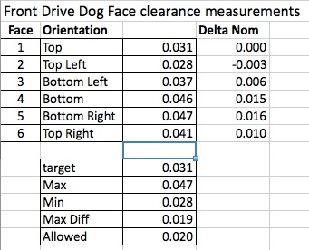
You can see that the front spacing is slightly larger and the differential is greater. The max differential is right at the (unrelaxed) spec limit. Not a lot can be done here since this is probably mostly due to the fact that the drive shaft is tilted up slightly from horizontal relative to the transmission and there is some built in twist to pre-compensate for the torquing of the frame under load. These should center out a little better when loaded, at least in the side-side differential department.
Overall I am pretty happy with this result as the distances are long and the potential for error is great. Just take your time and measure, measure, remeasure before drilling or cutting any metal.
Now, as with all other things on this machine, everything in this section gets pulled out and set aside until final assembly so I’ll be back to a stripped down frame again and my visitors will wonder if I am really doing anything other than napping in the shop.


Almost done with gearboxes. Starting to look into the tail rotor.
More Heli-nerd stuff: I put together the entire tail rotor driveshaft, aligned it, and re-measured the clearance between the mating drive dog faces. Two different feeler gauges were used with different combinations of fingers to average out the errors, In all cases each measurement agreed within 0.001” of each other
I am very pleased with the result at the rear. The shimming of the tail rotor gearbox is good and the drilling and fitting of the shafts didn’t change things that much. Cool. Everything is nicely centered on the nominal measurement and well under the allowed differential of 0.020”.
At the beginning of the video BJ gives you the target dimensions and at the end he sort of fudges and lets you know what you can really get away with. Happily I did not have to take advantage of the relaxed spec.
At the front shaft drive dog I got the following:
You can see that the front spacing is slightly larger and the differential is greater. The max differential is right at the (unrelaxed) spec limit. Not a lot can be done here since this is probably mostly due to the fact that the drive shaft is tilted up slightly from horizontal relative to the transmission and there is some built in twist to pre-compensate for the torquing of the frame under load. These should center out a little better when loaded, at least in the side-side differential department.
Overall I am pretty happy with this result as the distances are long and the potential for error is great. Just take your time and measure, measure, remeasure before drilling or cutting any metal.
Now, as with all other things on this machine, everything in this section gets pulled out and set aside until final assembly so I’ll be back to a stripped down frame again and my visitors will wonder if I am really doing anything other than napping in the shop.
Laser Measure TR Shaft
02/17/12 11:39 Filed in: All
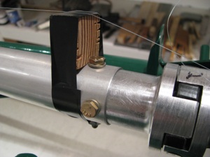
2/17/12 - I backed up a little. Even though I did BJ’s measurement procedure as detailed above, I realized that the two bearing blocks were only rough placed so the reference for measurements was not very exact to begin with. I fabricated a laser pointer alignment jig as others have done.
Get the smallest one you can find. Machine a spacer to sleeve it into the TR gearbox shaft. Realize that $2.99 laser pointers are not precision instruments. The beam is nowhere near coaxial, so as the shaft turns it circumscribes a circle at the far end. The shaft points to the center of that circle. It confirmed the CCW cant measured from the previous entry, but also showed a very slight downward point that I will have to shim out as well. That white plastic ring is a wire hanger just to hold the button down while measuring. I also machined a new front ring to hold the Laser diode more centered, but it didn’t help much. The beam is still canted off center. Leave a little slop in the sleeve so the pointer can be nudged to reduce the size of the circumscribed circle.
This is where it gets interesting only to Helicycle nerds. After using the laser to align the TR gearbox and adding 0.010 and 0.005 shims appropriately so the TR gearbox shaft is pointing as close as possible to the center of the output shaft on the main transmission I get the following:
1 - 0.031, 4 - 0.030 These are the top and bottom dogs. Delta=0.001”
2 - 0.029, 5 - 0.032 Top right and bottom left dogs. Delta=0.003”
3 - 0.028, 6 - 0.034 Bottom right and top left dogs. Delta=0.006”
So that’s a differential of 0.006” indicating an every so slight downward and CCW cant of the TR gearbox. This is much better than my initial attempt before fabricating my laser alignment tool and way tighter than the spec in the video. I should also note that I did the full string jig shaft alignment method prior to measuring
At the opposite end I measured the following clearances between the mating dogs at the main transmission end:
1 - 0.022, 4 - 0.044 These are the top and bottom dogs. Delta=0.022”
2 - 0.023, 5 - 0.043 Top left and bottom right dogs. Delta=0.020”
3 - 0.036, 6 - 0.032 Bottom left and top right dogs. Delta=0.004”
Not much can be done here. As expected this indicates that the main transmission is canted CCW as viewed from the top. This is expected as we built in some twist to balance out the expected torque. Also, the TR shaft is tilted slight up relative to the main xmission, so there’s not much that can be done there either.
I should note that nothing has been drilled yet, this is just placement and measuring to make sure everything fits and is spaced properly prior to drilling the shaft tubes to the bearings and dogs. Next up is to work out the appropriate bolt spacing and to figure out how I am going to drill the bolt holes perfectly.
Tail Rotor Shaft Start
02/06/12 11:20 Filed in: All
Started on the tail rotor and drive shafts. First task is to mount the TR gearbox. Off and on about a dozen times with lots of little trimming with the a rat tail file to open up the mounting holes. Nice and snug with no play when tightened down. The angle between the main mast and the TR shaft is about 89.5 degrees. BJ says less than a couple of degrees is OK, so there is no need to bugger up the mounting holes by trying to achieve a perfect 90. Better to keep them tight and live with the very minor angular misalignment.
Shaft sections are cut and first order fitting completed. A lot of fiddling required to get the lengths right. Fit is very tight over the bearing inserts, so it takes some sanding/polishing and a daub of grease to get them to slide on. That will be mostly removed on final assembly. There is a definite sequence of assembly required. Start at the front since the bearing blocks all mount from the rear.
Small cuts and sanding, then retry. Very time consuming.
To get the TR gearbox aligned required a thick washer on the bottom and a thin in the middle, and none at the top on the outside of the frame between the gearbox and the frame. This is almost the opposite of what BJ required in the video. Like his example, almost no left/right differential was required, mostly up/down.
At the TR gearbox the distance between the dogs and the mate is measured. The goal is less than 0.020 differential side-side or up/down. I numbered the ears and measured the following:
1 - 0.030, 4 - 0.029 delta = 0.001
2 - 0.025, 5 - 0.035 delta = 0.010
3 - 0.024, 6 - 0.034 delta = 0.010
It is numbered this way because measurements 1 and 4 are on opposite sides, 2-5 are opposite, and 3-6 are opposite. The greatest difference is 0.011 between any two and there is definitely less than 0.020 difference, so I am satisfied (almost). I may try to add my thinnest shim stock to the 3 right side bolts to try to remove the slight CCW cant (viewed from top) and get it as close to perfect as possible. Now is the time as it’s unlikely I will revisit this until final assembly.
Drilling Transmission
01/22/12 11:15 Filed in: All
OK. After procrastinating long enough and measuring and remeasuring, I finally drilled the transmission to the frame. Even with all my careful measuring and clamping, after I drilled and rebolted everything together snugly I went back and measured the offset. BJ wants the right side to have more pre-built offset by 1/4” measured at the first bearing block. When everything was final/final, I measured .350” more on the right. I was super careful. Something must have shifted ever so slightly during drilling. That extra tenth translates into about 5/100 of a degree. Hopefully this will not affect the final alignment too much.
The holes are all reamed and there is no detectable slop at all, which I think is probably more important.
I am happy with how the hood bearing block slides cleanly down to the hood with absolutely no touching of the hood metal. This means there’s no preload or stress on the mast imparted by the frame mounting.

The holes are all reamed and there is no detectable slop at all, which I think is probably more important.

I am happy with how the hood bearing block slides cleanly down to the hood with absolutely no touching of the hood metal. This means there’s no preload or stress on the mast imparted by the frame mounting.
Transmission Alignment
01/21/12 11:14 Filed in: All
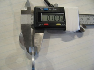
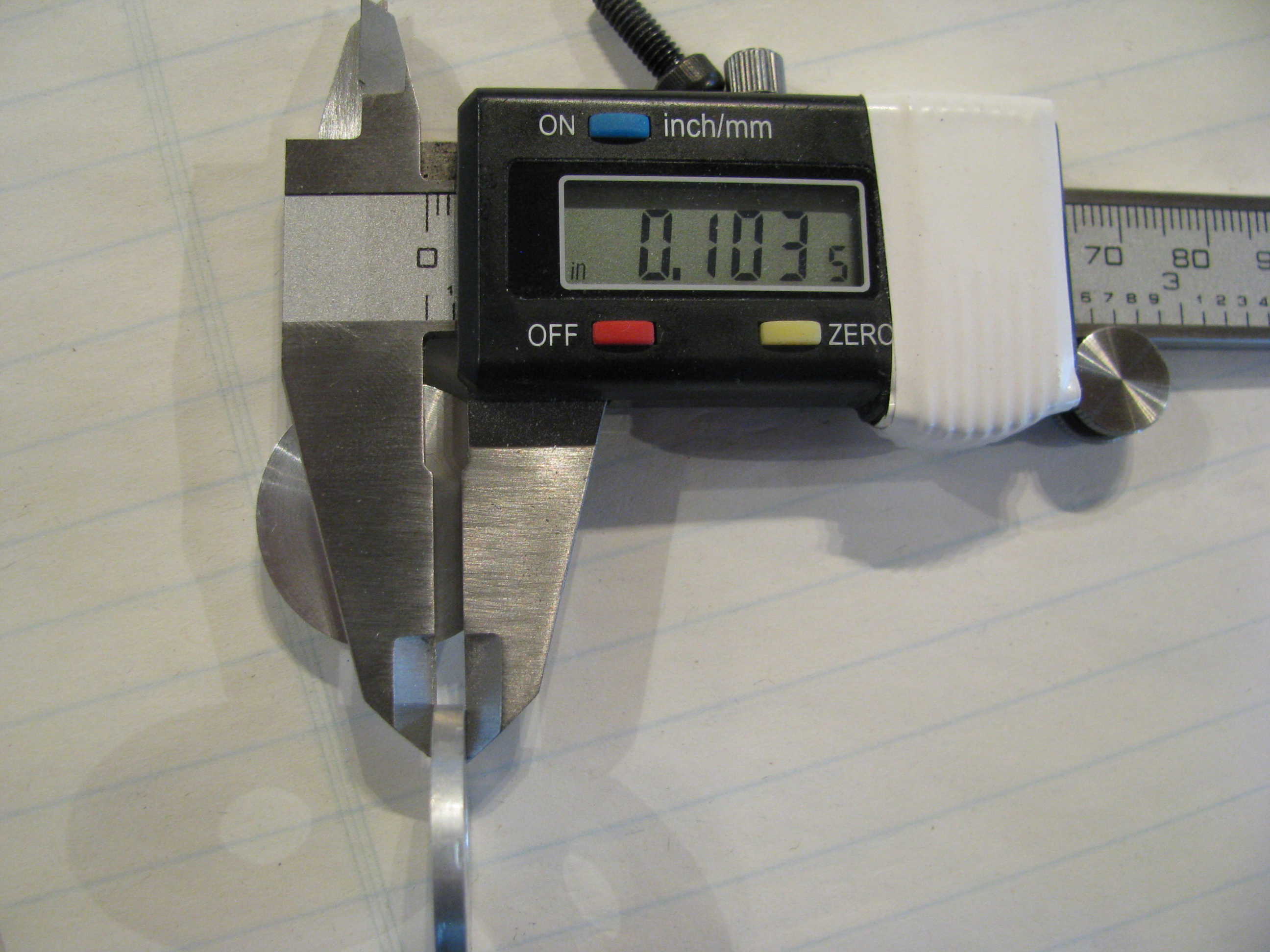
Fiddling with alignment of the main transmission. Fabricating spacers. Aligned everything. Measured gaps and now fabricating precision spacers. First was the left side. The gap between the mounting tab is 0.103 on the outside and tapers to 0.089 on the inside. The tab has a little tilt and the casting is not exactly level-flat. Roughed a blank on the lathe. Fashioned a holder, then faced down to 0.103 and drilled out the center hole to 5/16”. Finally hand-sanded the tilt from 0.103 outside to 0.090 inside and fit to ship.


Initial Transmission Fit
01/14/12 00:09 Filed in: All
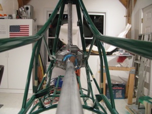
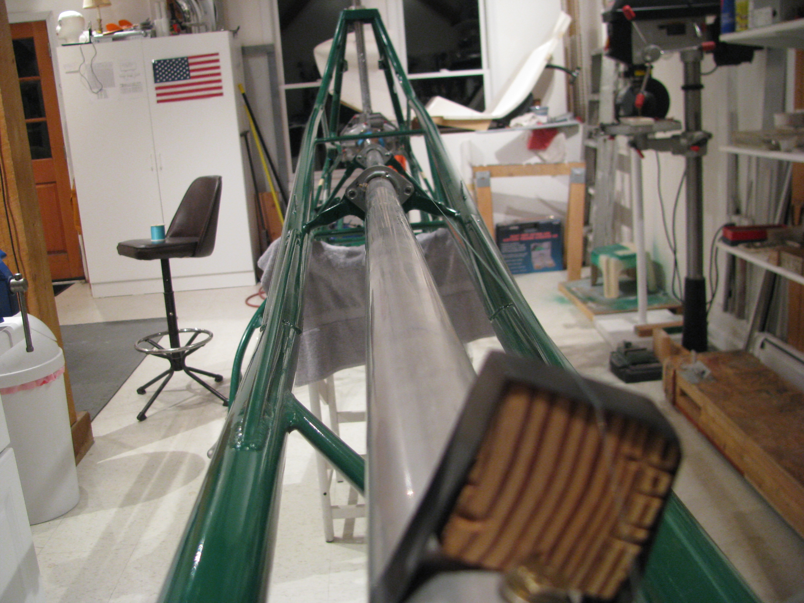
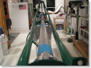
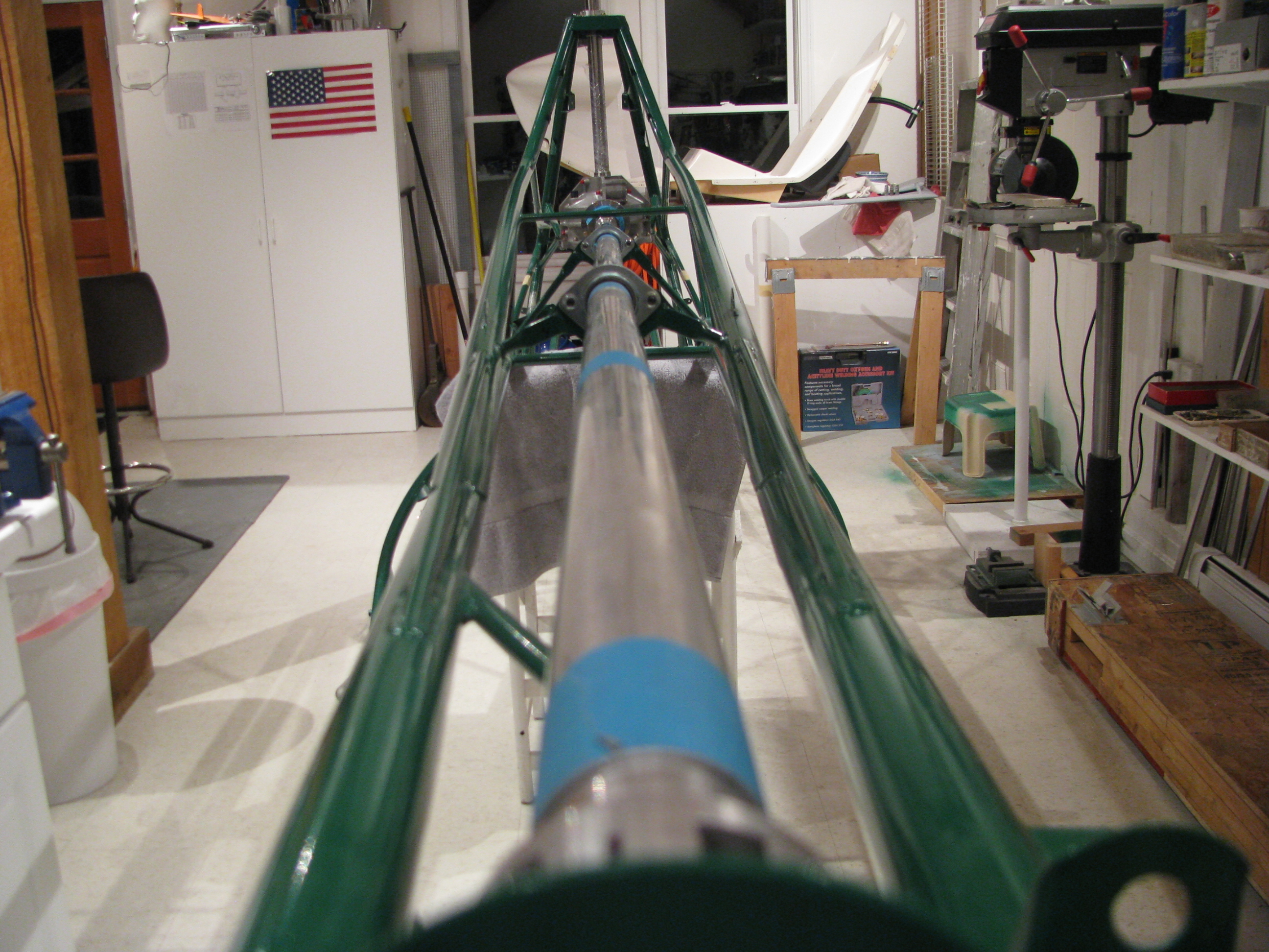
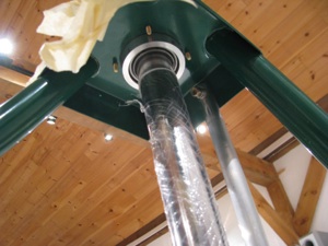
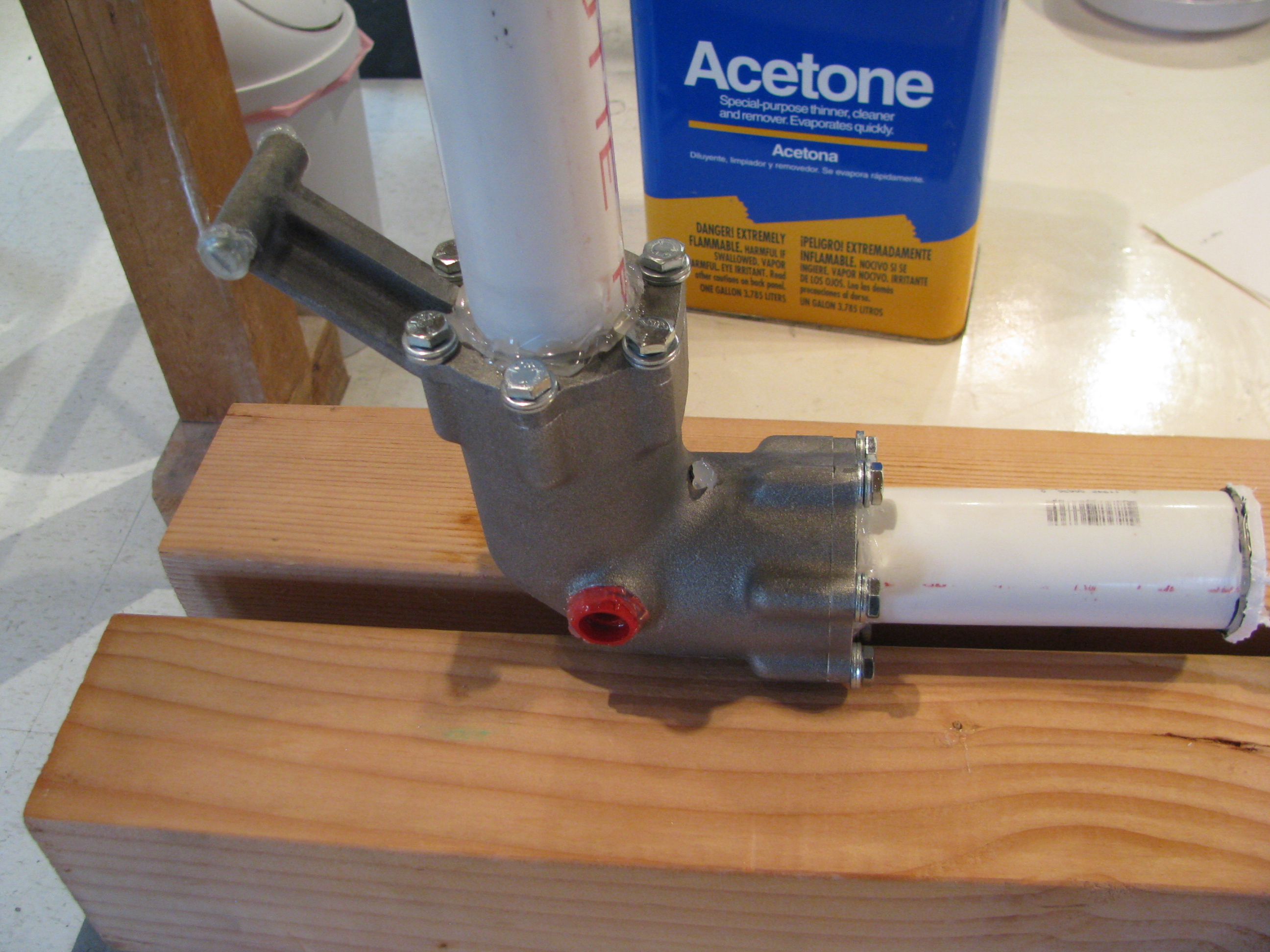
Hooray! Transmission preliminarily in place. That’s a piece of 2” PVC pipe, which fits perfectly to protect the shaft while sliding into position. This is definitely a 2 person operation.
Once in place I clamped a piece of wood underneath the transmission so I can lower it a few inches to clear the tabs when needed.
Ran the alignment string and rough set the pre-load offset angle (very precise twist/measure/clamp/repeat).
The undrilled side tab was not exactly parallel, so it had to be bent down about 0.75degree.
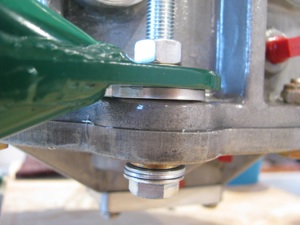
When the pre-drilled bolt was snugged, the first to bottom was the undrilled side. It also looks like the inner side of the tab touches first. I could either make an angled shim or perhaps take a touch of aluminum off the casting. I don’t want to stress the tab welds by trying to impart a twist in the steel tab.
With the undrilled (right) side bottomed there’s a 63 mil gap between the left-side side tab and the casting. The photo also makes it look like they are not parallel. I’ll double check to make sure this is not a trick of the camera lens.

With everything jigged and clamped you can see the uneven gap at the hood bearing. It’s maybe 0.040” at its largest which is exactly on the right side of the ship. I think much of this is probably due to the built-in slight leftward tilt of the mast. I’ll work the main mounts before worrying to much about this.
I can judge the left/right tilt of the main mounts by making sure this bearing housing slides up and down easily when the main mounts are in position and clamped. I guess the fore-aft tilt of the main transmission is locked in place by the lift strut. I’ll have to play with that a bit. I will probably diddle around with this for a few hours to make sure every angle and clearance is understood and addressed before making permanent changes (ie: drilling that undrilled tab and the lift strut mount). Mistakes here would be difficult to fix and very expensive.
Transmission Prep
01/01/12 00:07 Filed in: All
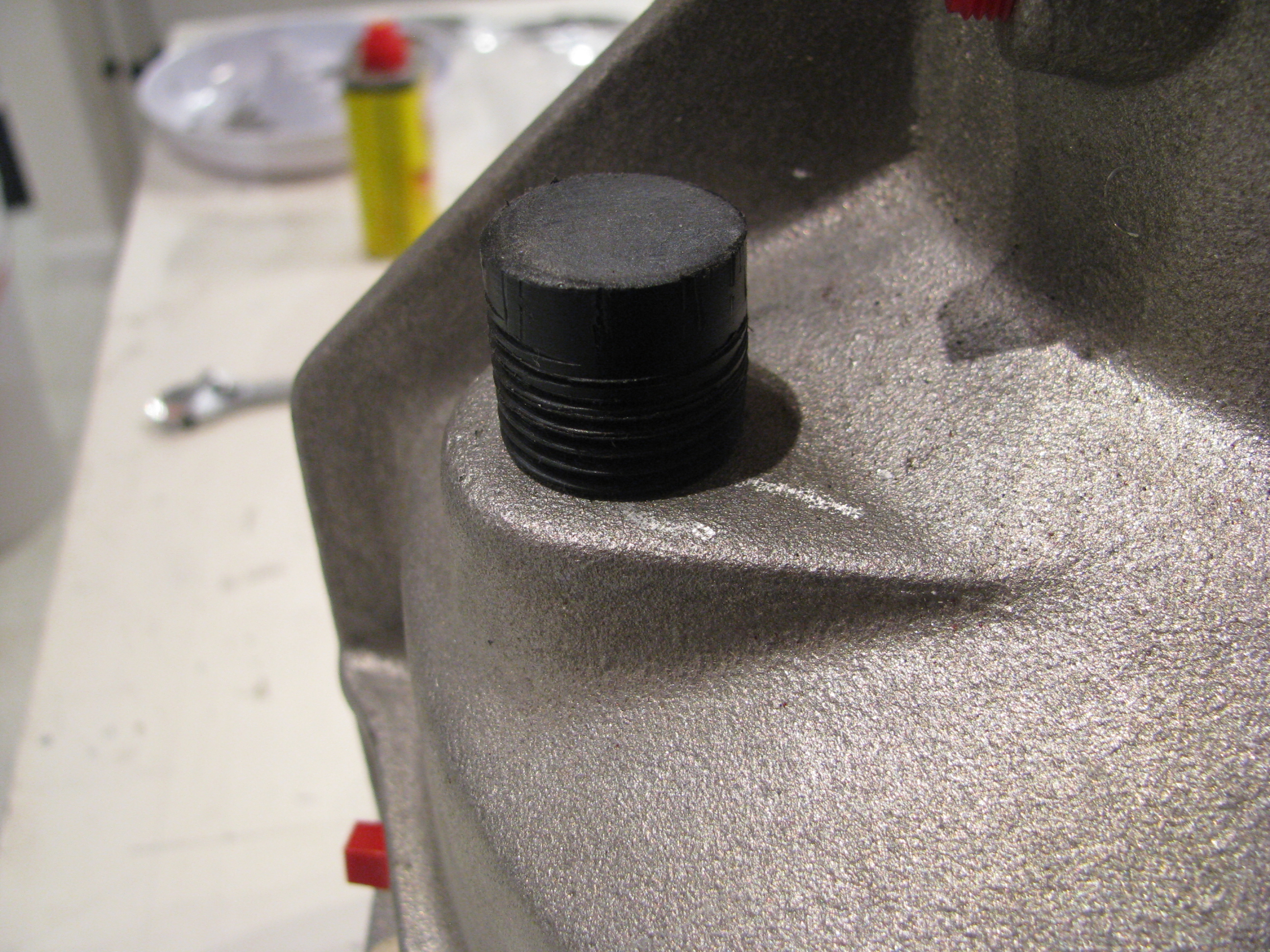
Here is why my progress slows to a crawl sometimes. BJ says to make a little wooden plug to cover the transmission fill during painting. Well, instead of wood, I turned this this little plastic block down on the lathe and then threaded it to 1/2” NPT pipe thread. I messed up the threads and had to make a new one. Of course cutting plastic on the lathe is very messy, so I had to clean up the shop afterwards. All told about an hour and a half to make a stupid little plug.
Sandblasted with 80grit followed by 220, then wirebrushed with stainless steel and then a brass brush. It looked fantastic before the painting, but of course that wouldn’t have lasted. Two coats of POR-15 clear. One light to “seal” the casting, then one medium-heavy to level it out all with a brush. It looks candy-coated now.
It took almost a full week of curing before it stopped feeling tacky.
TR Gearbox Prep
12/30/11 23:39 Filed in: All
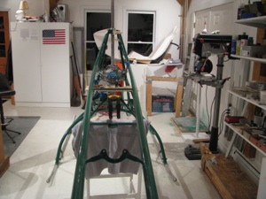
OK. Time for the serious stuff; Mounting the main transmission, tail rotor shaft and tail rotor gearbox. Once the main transmission is mounted, the tail rotor shaft can be fabricated and aligned. That’ll go a really long way to making the whole thing start to look like a helicopter. To date the bits go on, then they come off, so anytime my kids stop by the shop it looks like I am back a square one.
Baby Steps: I masked off the important bits of the rail rotor gearbox. That’s just PVC with hot glue around the bearings. The the exterior got a sandblast with 220 grit glass, blown off, and rinsed with acetone.
Those are cheap HW store 1/4-28 bolts since they’ll get blasted too.
I ordered a gallon of the Allisyn ProGear21 75W-90W oil today. Holy crap! $60/gallon.

Wow. POR-15! Magic stuff. Two coats and this thing looks great. It’s like coating it with a form-fitting layer of glass. From reading the web I have to resist the strong temptation to touch it since it can take days to completely dry.
I wanted to try something small before committing to the main transmission with the POR-15. I have no reservations at this point. Some folks use color on these parts, but I like the effect of keeping the mechanical parts looking like manly hardware.
Important note on the POR-15: Don’t mix it in a plastic cup! The first little bit sat for a minute, then ate through the cup (polycarbonate, I think) and then ate through the coat of polyurethane on my workbench. Strong stuff. I had to steal a glass form the kitchen, then dig around for a camel hair brush instead of the little plastic one I was going to originally use.
I also ordered a transmission lift strut from Hap Miller today (nice guy!). I’ve heard good things about it from Juan R’s site and really don’t like the “heat and smash” tubes that are used in a number of places. I’ll probably use his tail fin braces as well.
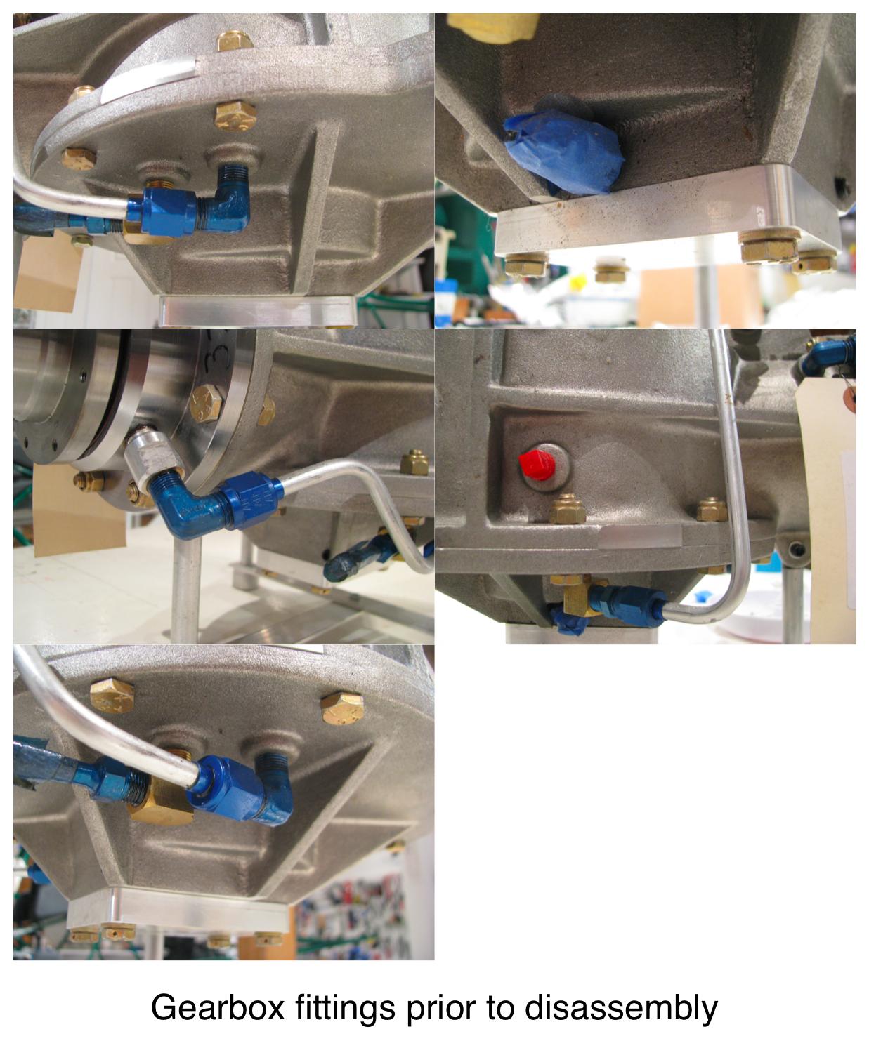
Prior to painting the main transmission I took a series of photos so I would have a reference for where the various tubes and fittings go on reassembly.
GearboxPlumbing_1.jpg
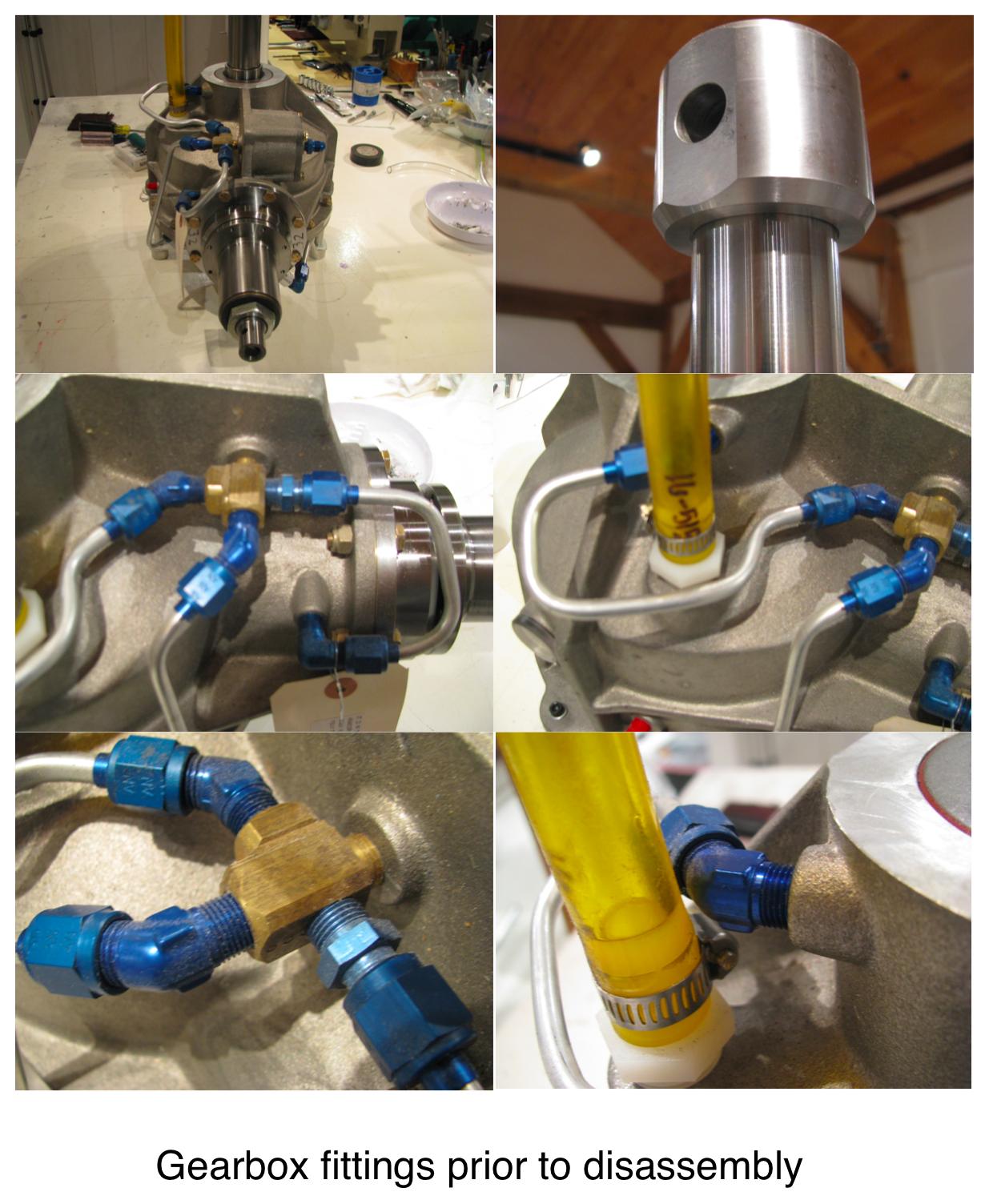
GearboxPlumbing_2.jpg
GearboxPlumbing_3.jpg