
Laser Measure TR Shaft
02/17/12 11:39 Filed in: All
2/17/12 - I backed up a little. Even though I did BJ’s measurement procedure as detailed above, I realized that the two bearing blocks were only rough placed so the reference for measurements was not very exact to begin with. I fabricated a laser pointer alignment jig as others have done.
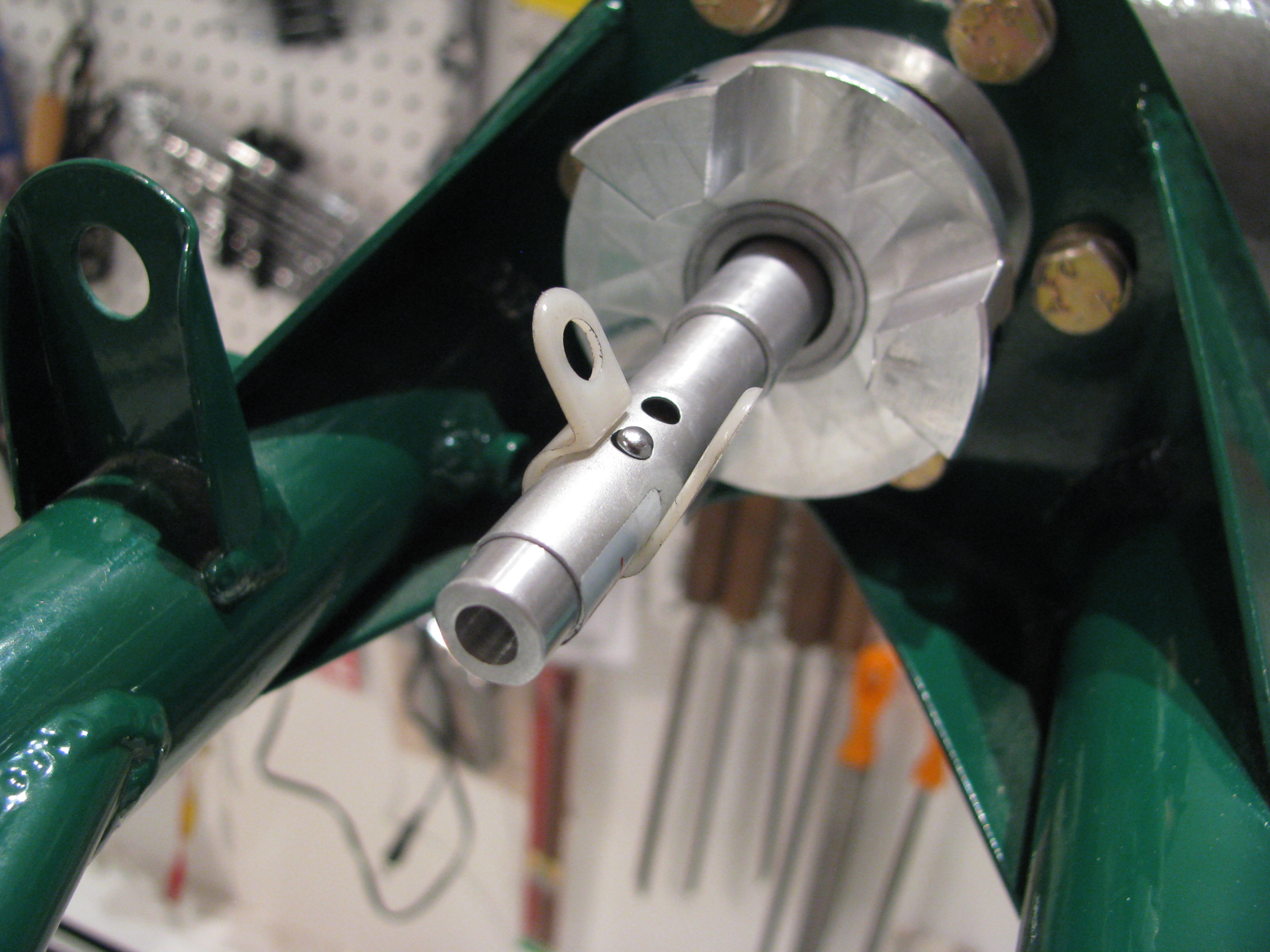
Get the smallest one you can find. Machine a spacer to sleeve it into the TR gearbox shaft. Realize that $2.99 laser pointers are not precision instruments. The beam is nowhere near coaxial, so as the shaft turns it circumscribes a circle at the far end. The shaft points to the center of that circle. It confirmed the CCW cant measured from the previous entry, but also showed a very slight downward point that I will have to shim out as well. That white plastic ring is a wire hanger just to hold the button down while measuring. I also machined a new front ring to hold the Laser diode more centered, but it didn’t help much. The beam is still canted off center. Leave a little slop in the sleeve so the pointer can be nudged to reduce the size of the circumscribed circle.
This is where it gets interesting only to Helicycle nerds. After using the laser to align the TR gearbox and adding 0.010 and 0.005 shims appropriately so the TR gearbox shaft is pointing as close as possible to the center of the output shaft on the main transmission I get the following:
1 - 0.031, 4 - 0.030 These are the top and bottom dogs. Delta=0.001”
2 - 0.029, 5 - 0.032 Top right and bottom left dogs. Delta=0.003”
3 - 0.028, 6 - 0.034 Bottom right and top left dogs. Delta=0.006”
So that’s a differential of 0.006” indicating an every so slight downward and CCW cant of the TR gearbox. This is much better than my initial attempt before fabricating my laser alignment tool and way tighter than the spec in the video. I should also note that I did the full string jig shaft alignment method prior to measuring
At the opposite end I measured the following clearances between the mating dogs at the main transmission end:
1 - 0.022, 4 - 0.044 These are the top and bottom dogs. Delta=0.022”
2 - 0.023, 5 - 0.043 Top left and bottom right dogs. Delta=0.020”
3 - 0.036, 6 - 0.032 Bottom left and top right dogs. Delta=0.004”
Not much can be done here. As expected this indicates that the main transmission is canted CCW as viewed from the top. This is expected as we built in some twist to balance out the expected torque. Also, the TR shaft is tilted slight up relative to the main xmission, so there’s not much that can be done there either.
I should note that nothing has been drilled yet, this is just placement and measuring to make sure everything fits and is spaced properly prior to drilling the shaft tubes to the bearings and dogs. Next up is to work out the appropriate bolt spacing and to figure out how I am going to drill the bolt holes perfectly.