
2012
Turbine Prep
09/29/12 14:13 Filed in: All
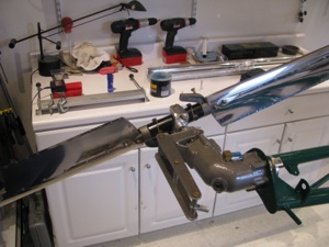
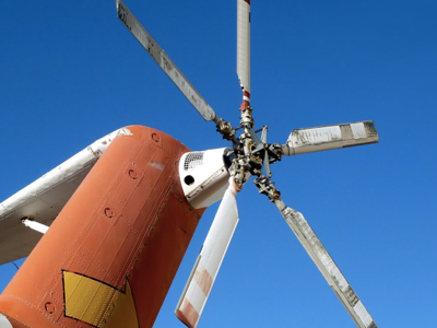
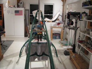
Back to turbine prep. Summer is over. Time for serious building. Adding the numerous fittings and prep for the plumbing. While at Reno I saw N168SK, a Helicycle belonging to James Kent, which was out on static display. Wow! A beautiful machine and represented the breed well.
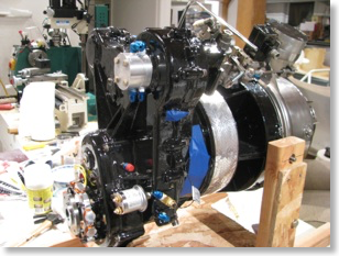
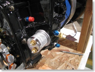
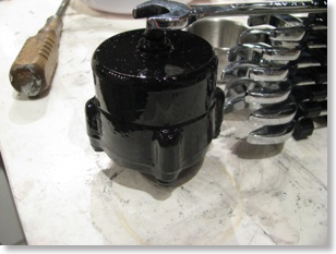
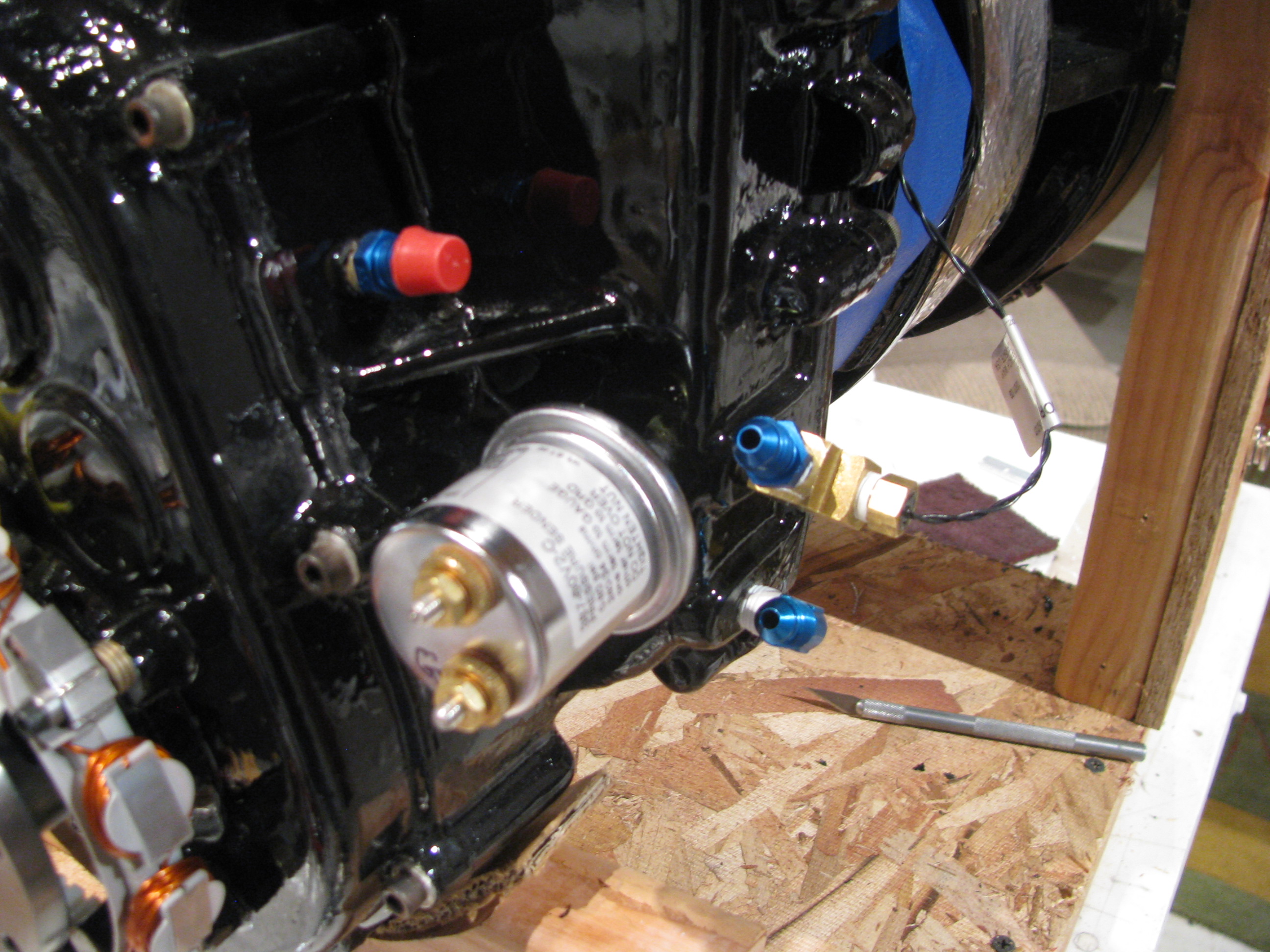
Various plumbing fittings, safety wiring, and painting of the oil filter housing.

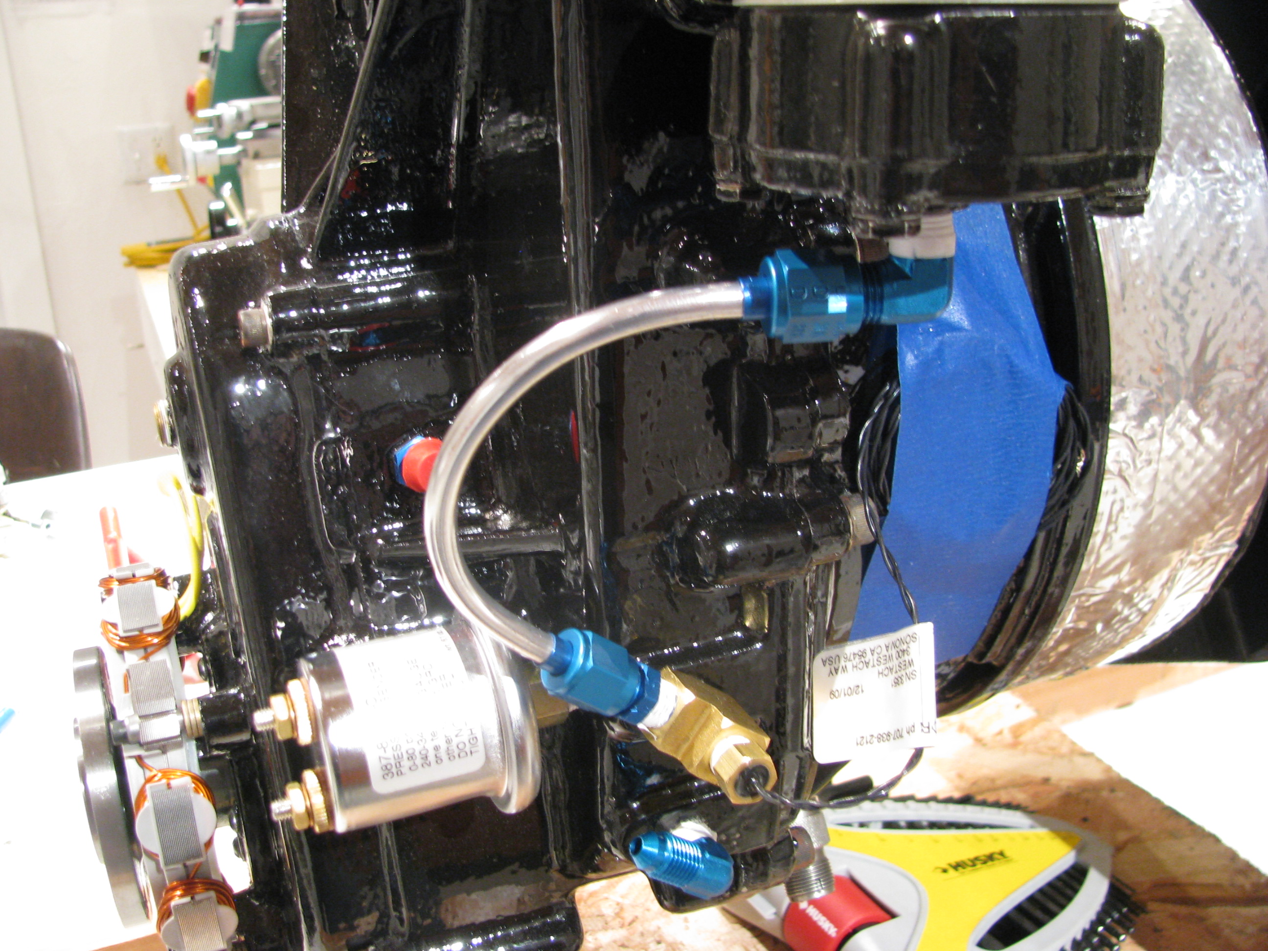
My first oil line. I think I may have “overflared” the ends as a little ridge extruded out between the flare clamp dies which prevents the retainer ring from seating fully. This one is coming back. I practiced on a couple, but probably should have intentionally under and over flared to get a feel for what that looks like, Again, my second helicopter will be perfect.
Takes about 3 minutes to polish the line and makes a huge improvement in appearance.
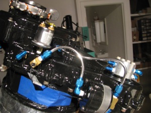
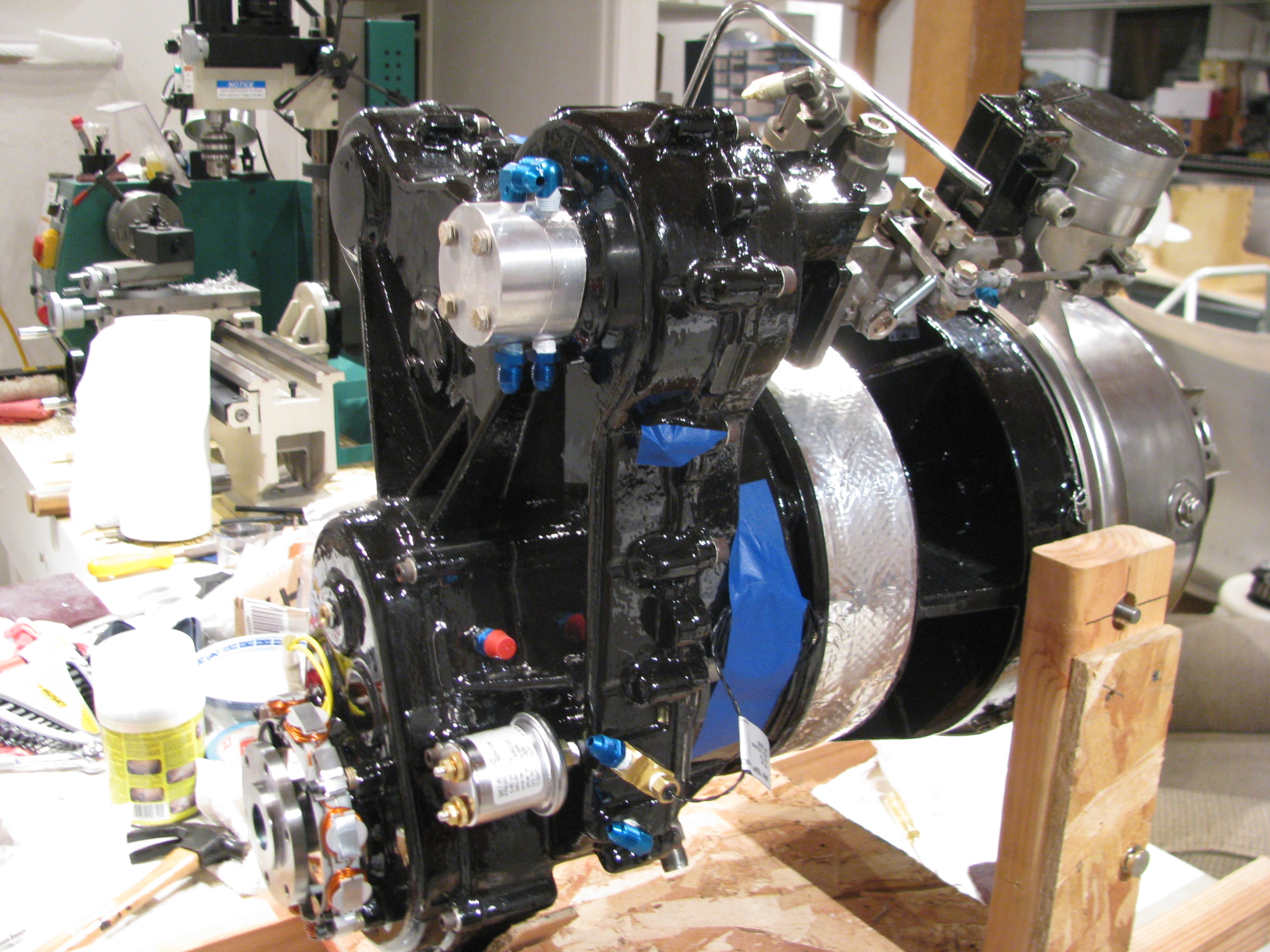
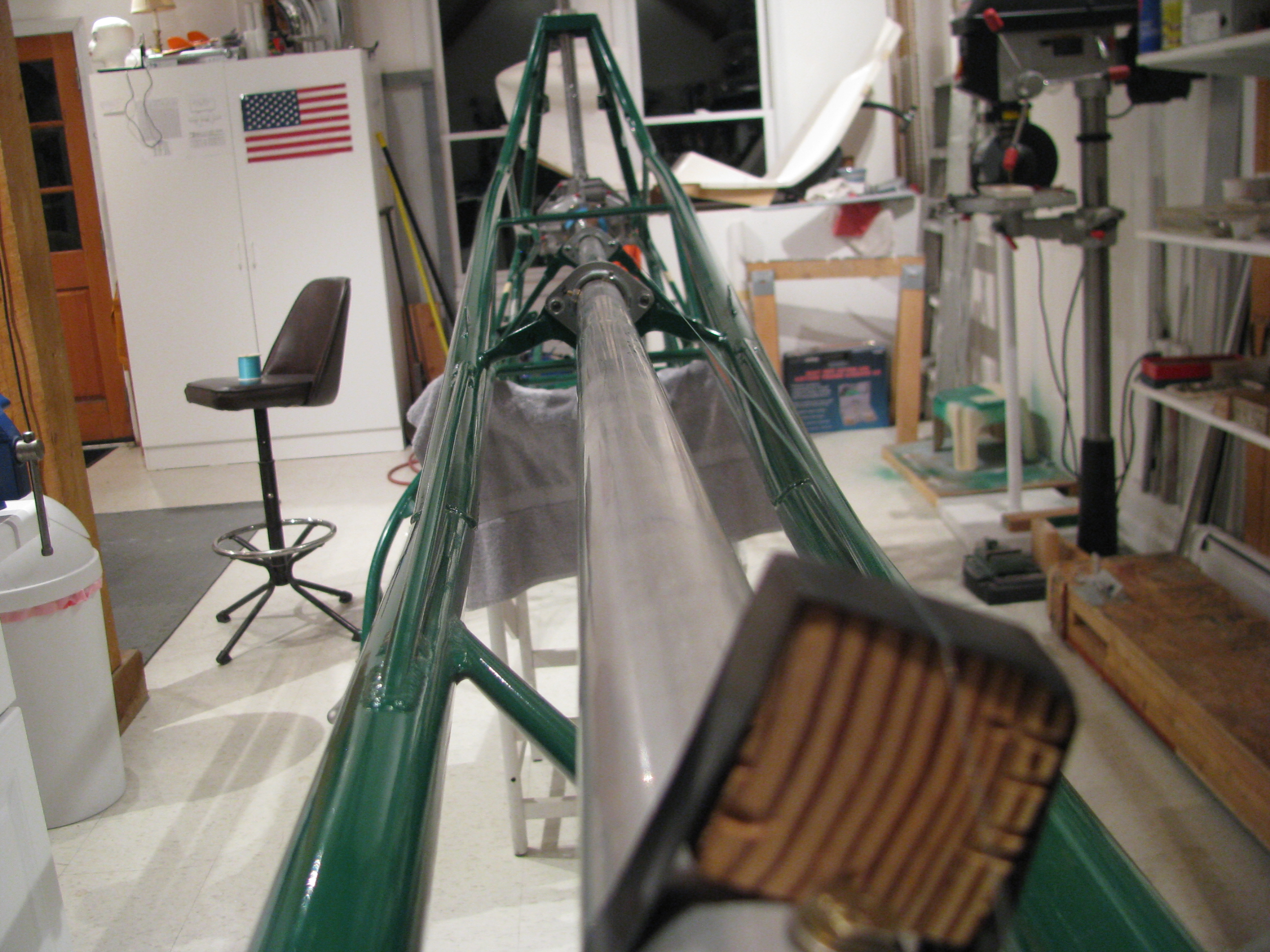
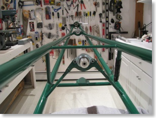
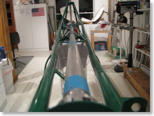
Adding more lines. Engine is tilted up for better access to lower lines.
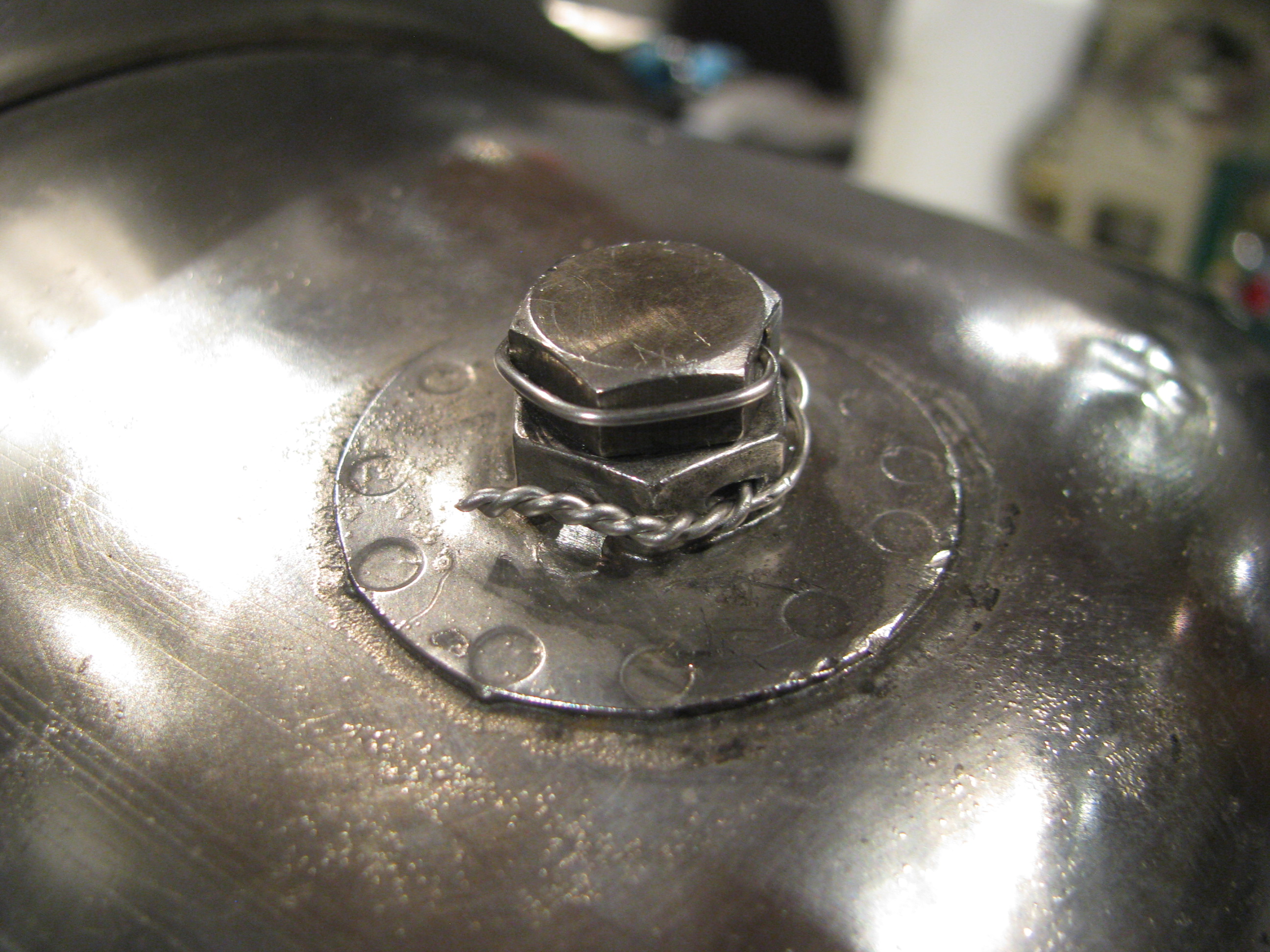
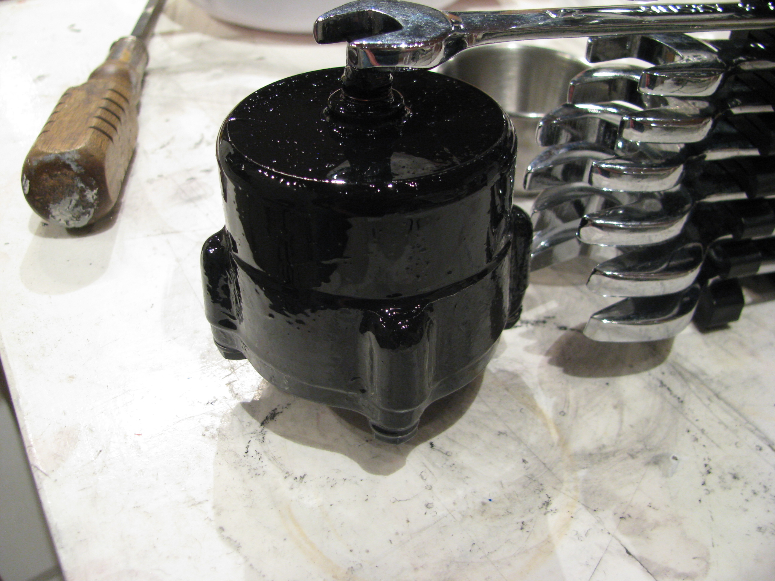
Various plumbing fittings, safety wiring, and painting of the oil filter housing.
My first oil line. I think I may have “overflared” the ends as a little ridge extruded out between the flare clamp dies which prevents the retainer ring from seating fully. This one is coming back. I practiced on a couple, but probably should have intentionally under and over flared to get a feel for what that looks like, Again, my second helicopter will be perfect.
Takes about 3 minutes to polish the line and makes a huge improvement in appearance.

Adding more lines. Engine is tilted up for better access to lower lines.
Drilling and Aligning Fins
09/03/12 13:38 Filed in: All

To get the horizontal fin at the correct 5° angle, and to keep the relationship of the vertical fin reasonable and the position of the rear mounting hole centered in the doublers (don’t worry, it would make sense if you were building one), I found things to work better if I placed a 0.125” spacer under the front vertical fin mount. This also allowed for the milling of a tilt to account for angular mismatch between the fin and the frame mount. Quick job on the Grizzly.

When I first started making these tubes I thought I would simply use my fabricated tubes as templates and then go have a welder make “real” tubes with a welded endplate, but I must say that I am actually pretty pleased with the results. The double MAP torch trick seems to work as Home Depot MAP torches do not seem to burn hot or concentrated enough to thoroughly melt the tube, but the flame temp (3600 degrees) is well above the annealing temp (1590 degrees) of 4130 steel.

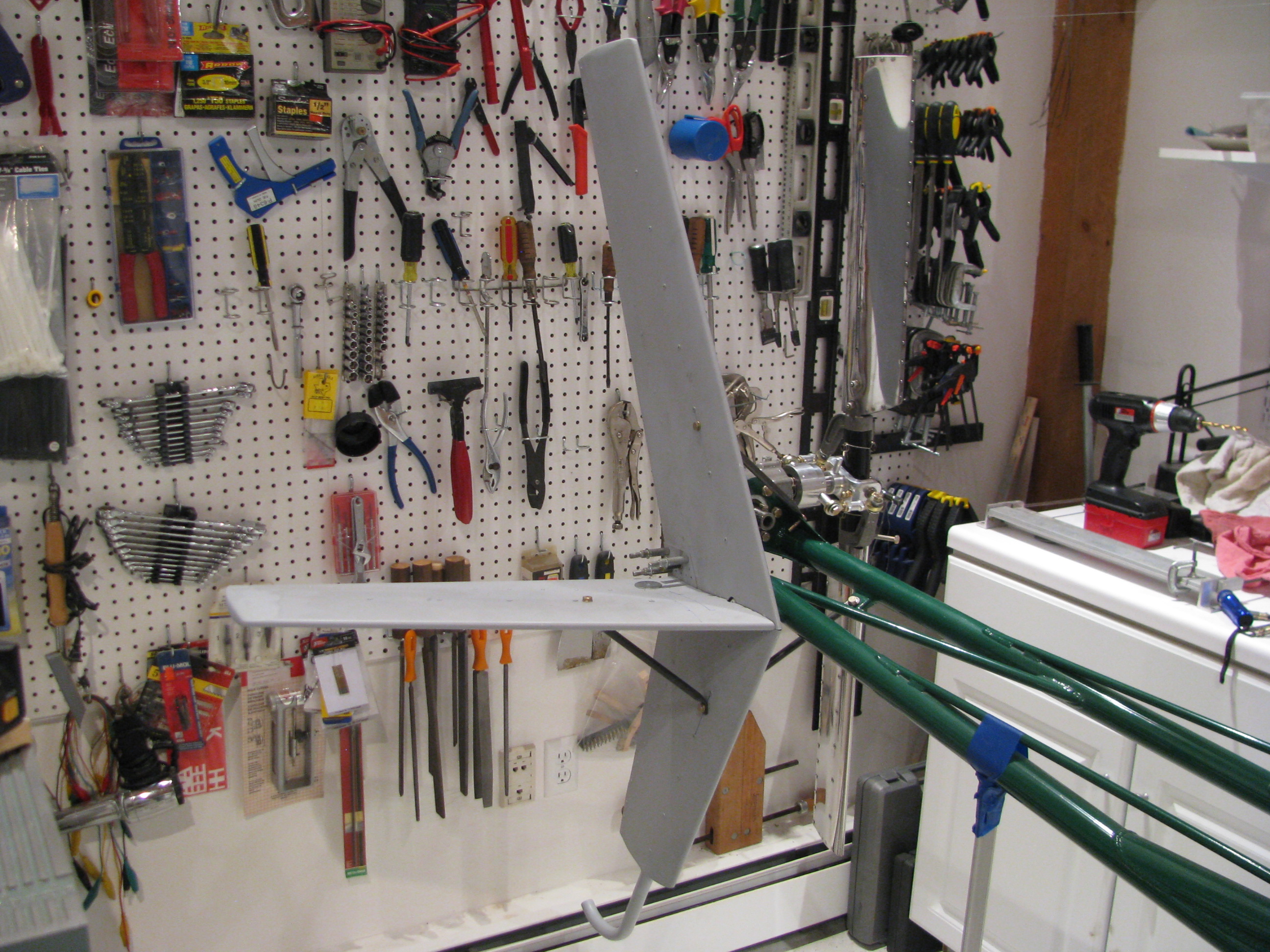
The finished (almost) fin mounting job. I just need to redo the single lower tube, final rivet the central fin doublers, drill the horizontal fin to its mounting stub tube and fashion a bracket at the rear of the horizontal for added support to the vertical. One evening.
Of course during flight checkout all these may have to be boogered around a bit, but for now I am pleased that they are spot-on the planned dimensions and angles.
Ground Plane Mounting
08/20/12 17:09 Filed in: All
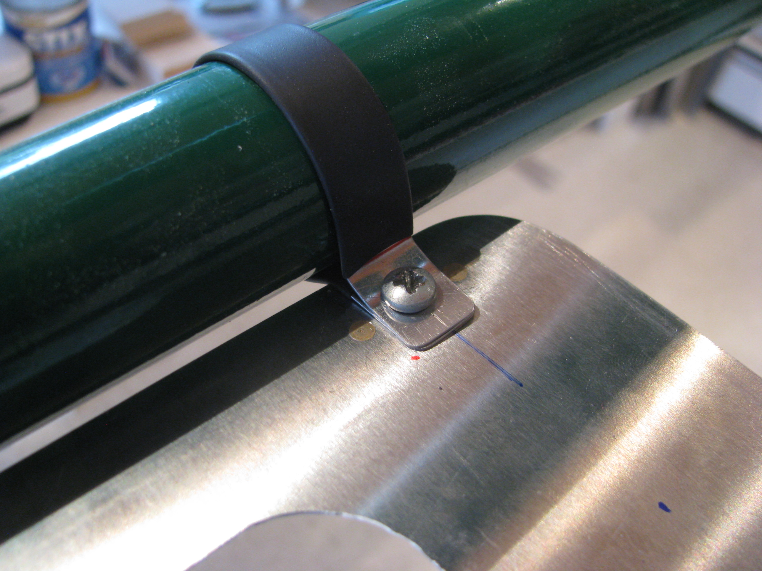
Completed the ground plane. I couldn’t see using Adel Clamps to secure it. Overkill. Instead I used little strips of 0.025 covered in shrink tube screwed through the ground plane to nutplates riveted to the bottom of the ground plane. Nice and tight, and it weighs next to nothing.
Fin Brace Tubes
08/20/12 13:37 Filed in: All
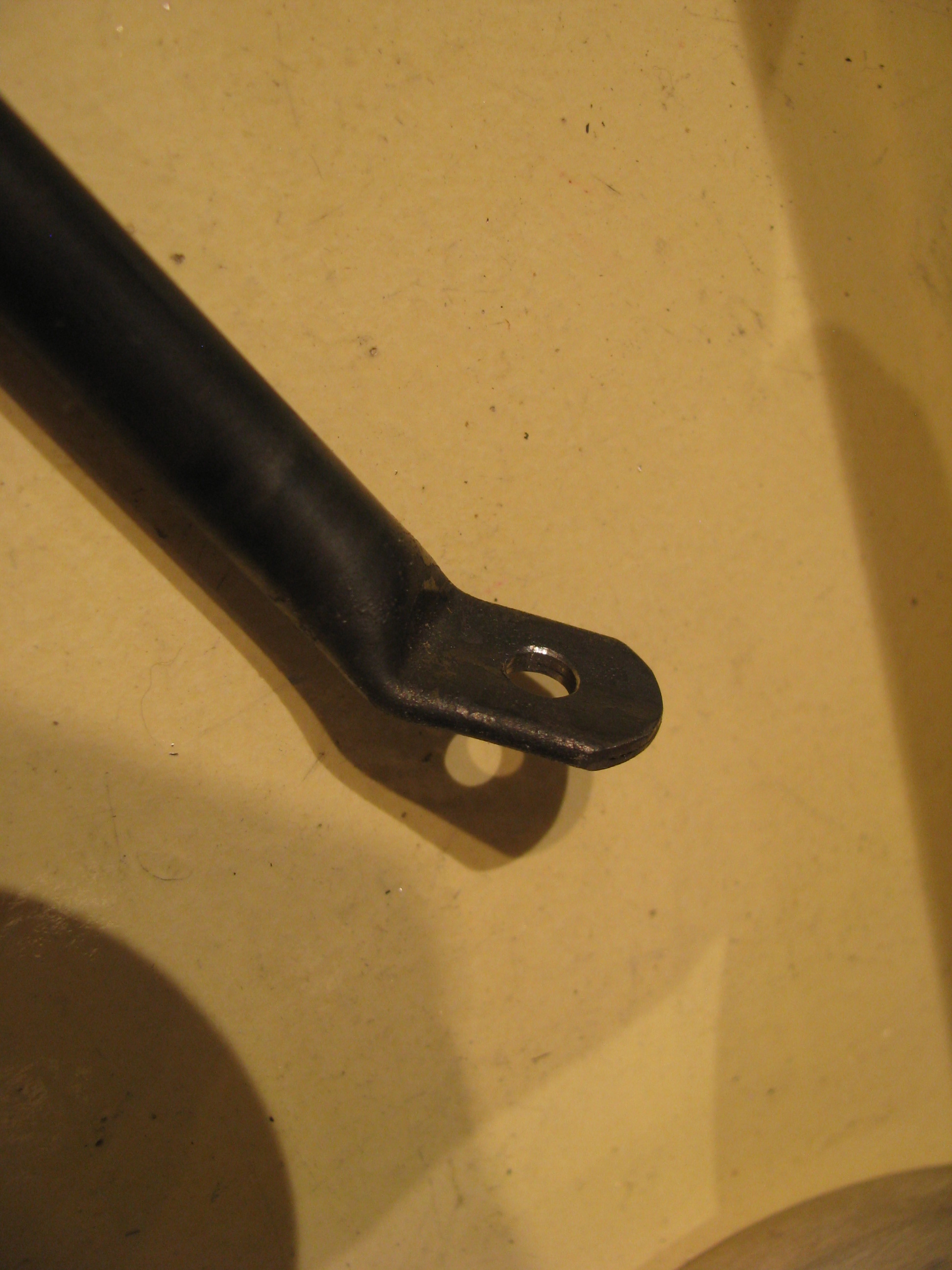
I got out my torch and bent the tubes that are to support and align the tailfeathers. As with most operations that are new to me, the first one came out great, then the second two were sloppy I need a better device for squeezing and bending the heated tube that is a little more precise. I am going to do some experiments to see how strong the heated and bent tubes are as that is a questionable procedure in my mind. I am heating the tube with a pair of MAP gas torches which gets the tubes bright orange, but not cherry red. Good thing I bought an extra 3 feet of tubing from A.S.
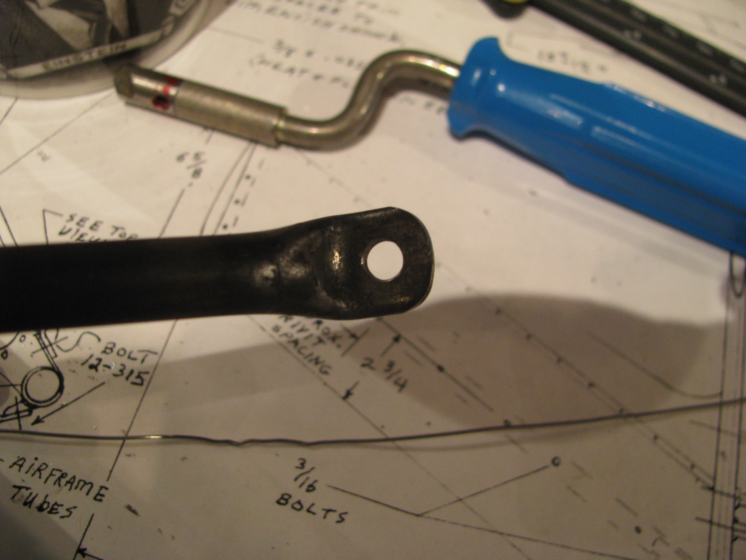
I ended up grinding some generous curves on the outside of a couple of chunks of aluminum angle to cover the vice jaws, so that when I squeezed, the hot tubing it would have a gentle bend instead of a sharp break at the end of the angle.
Every time the tube is heated and squeezed the aluminum picks up some scale from the steel that has to be scraped off since it’s hot enough to braze the scale to the aluminum surface and stick.
Once the hot tube touches the jaws you have about 2 seconds to complete the bend before the heat is wicked away and the tube re-hardens.
Once the squeeze and the angle look good, reheat and get the whole bend bright orange to re-anneal and let it cool very slowly. I played around with more rapid cooling on test pieces and it makes a huge difference. I had one piece so hard that drill bits could not get any bite at all and just burned.
Ground Plane
07/24/12 16:39 Filed in: All
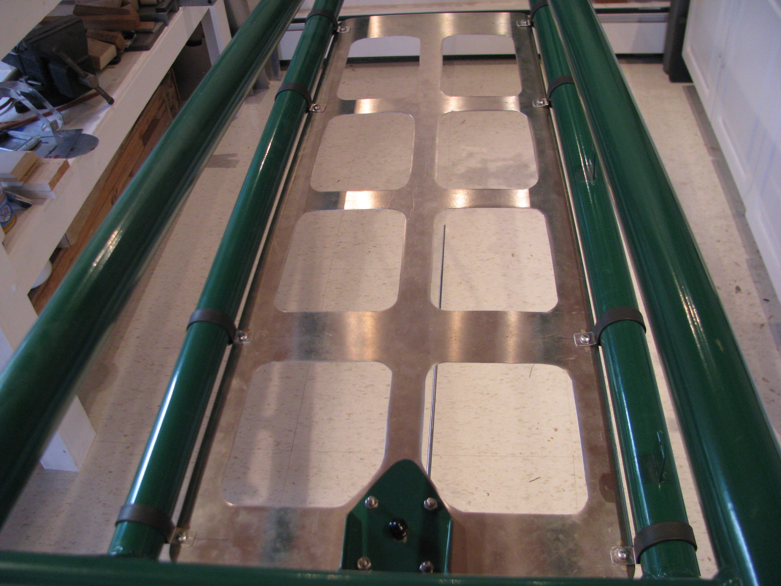
After having read Juan Rivera’s web site I decided that I would include a ground plane to improve the performance of the VHF communications antenna. The comm frequency range is 118 to 136 MHz. Therefore the 1/4 wavelength range is 21 to 25 inches. The sheet is 28 inches long. The longest diagonal opening is about 6.5 inches. No hole should be more than 1/10 wavelength (8.5 to 10 inches) so this should work well.
Cutting the sheet was a royal pain, but I didn’t want to just rivet strips together as the impedance across the joints would have adversely affected the RF performance of the ground plane. Drawing for the ground plane sheet is GroundPlane_B_072012.pdf.
Machining Shaft Dogs
07/15/12 11:44 Filed in: All
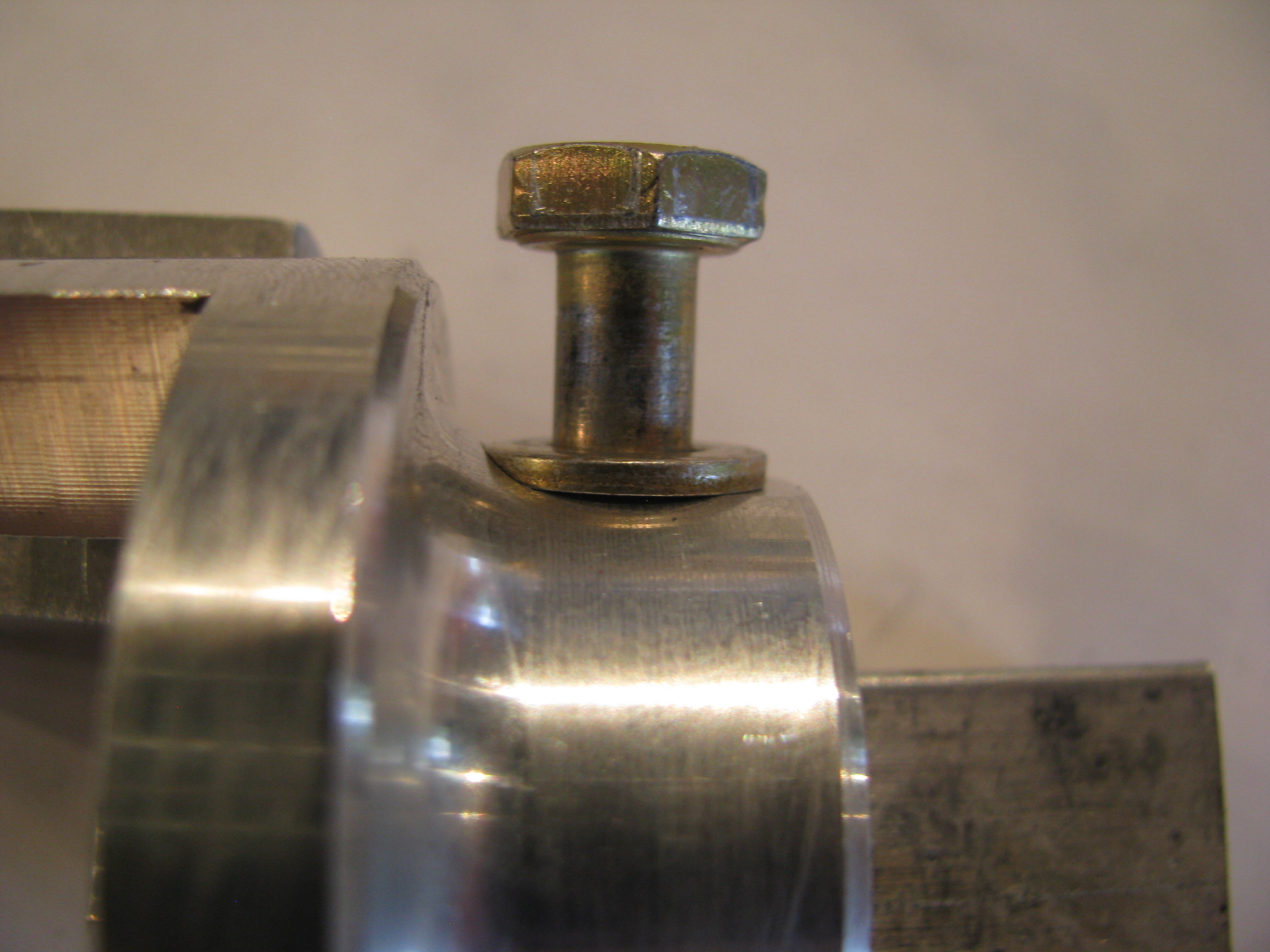
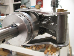
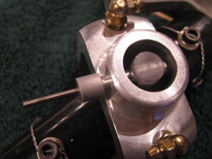
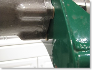
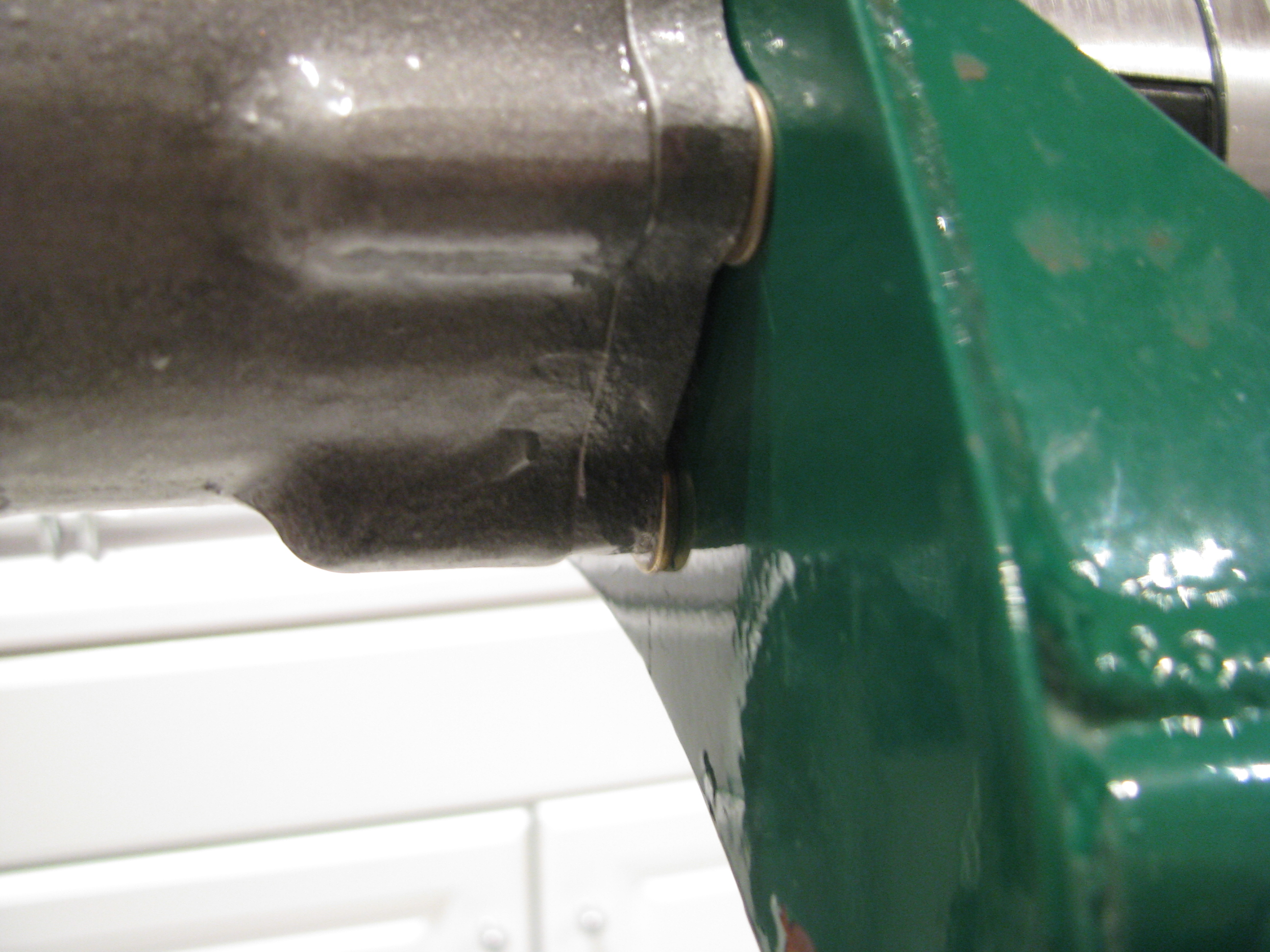
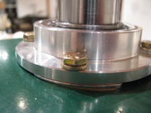
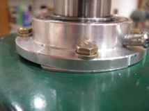
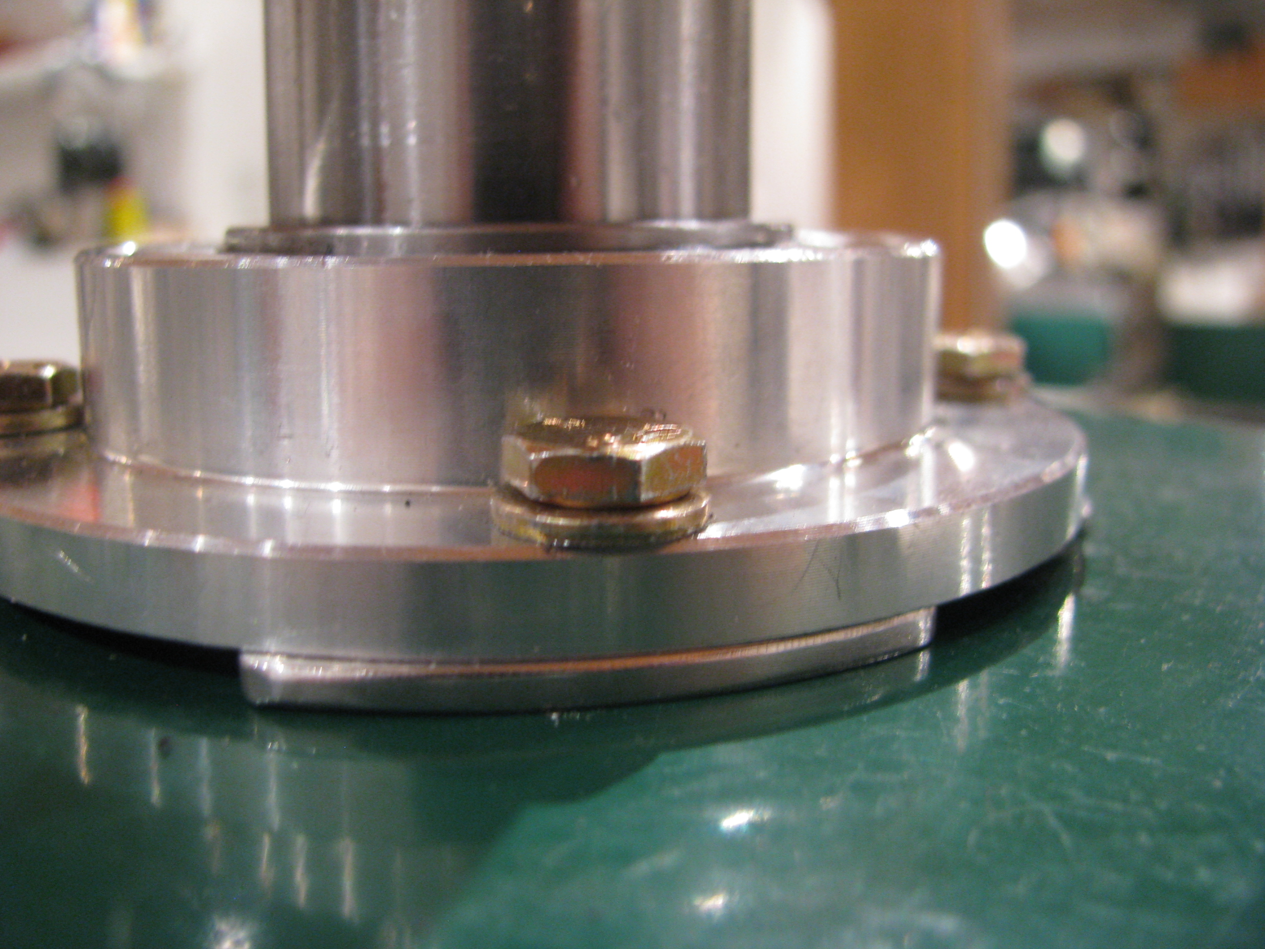
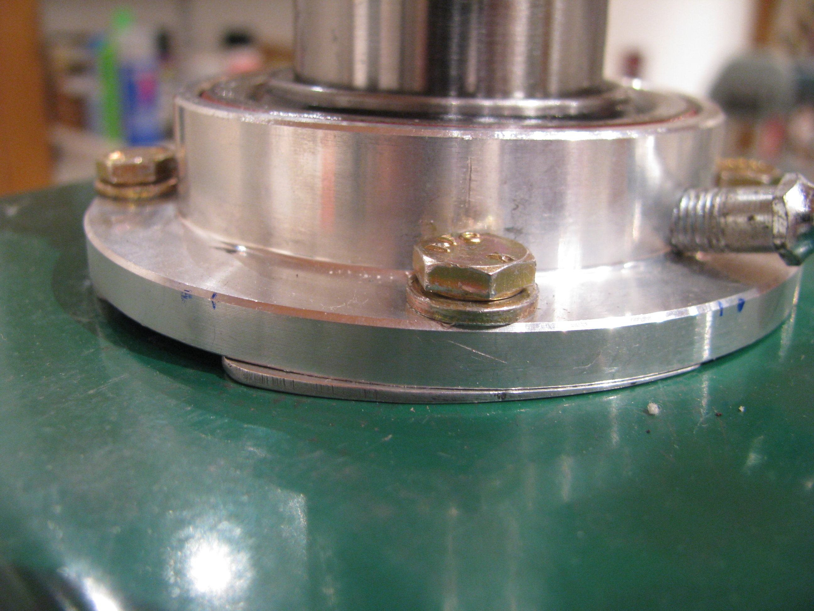
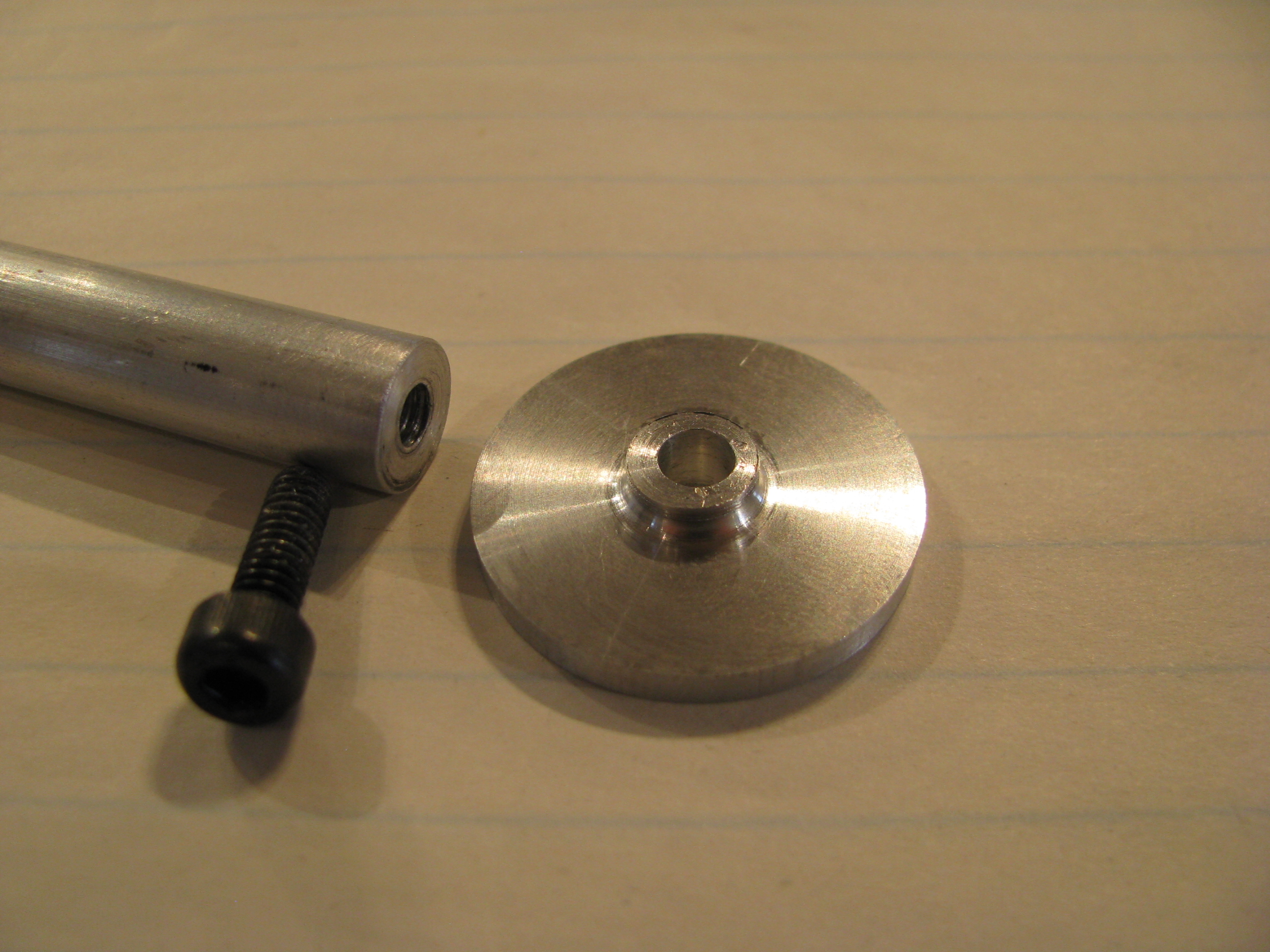
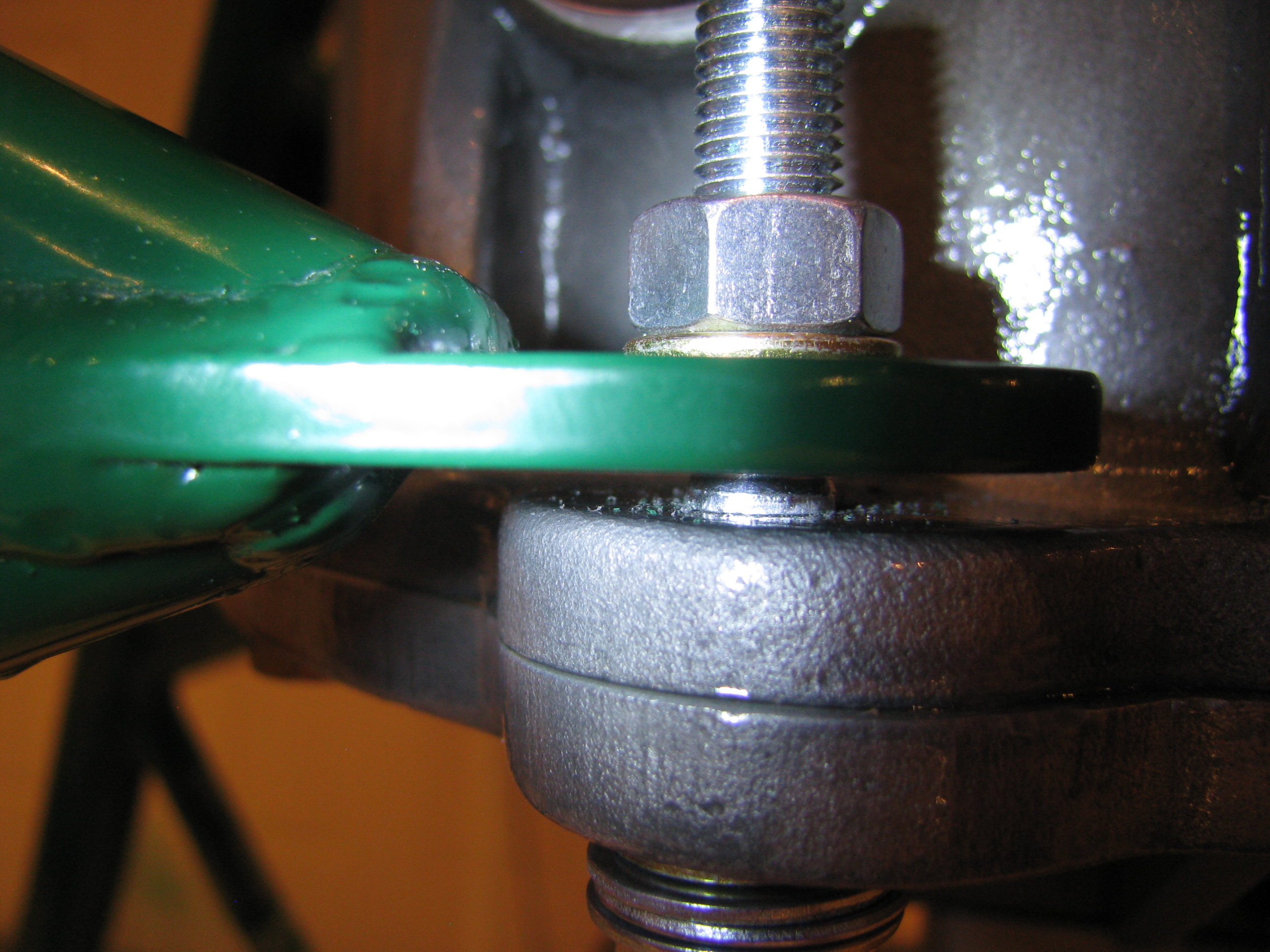
One of the little tasks I had pending was to clean up the bolt seats on the tail rotor drive shaft dogs.
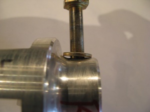
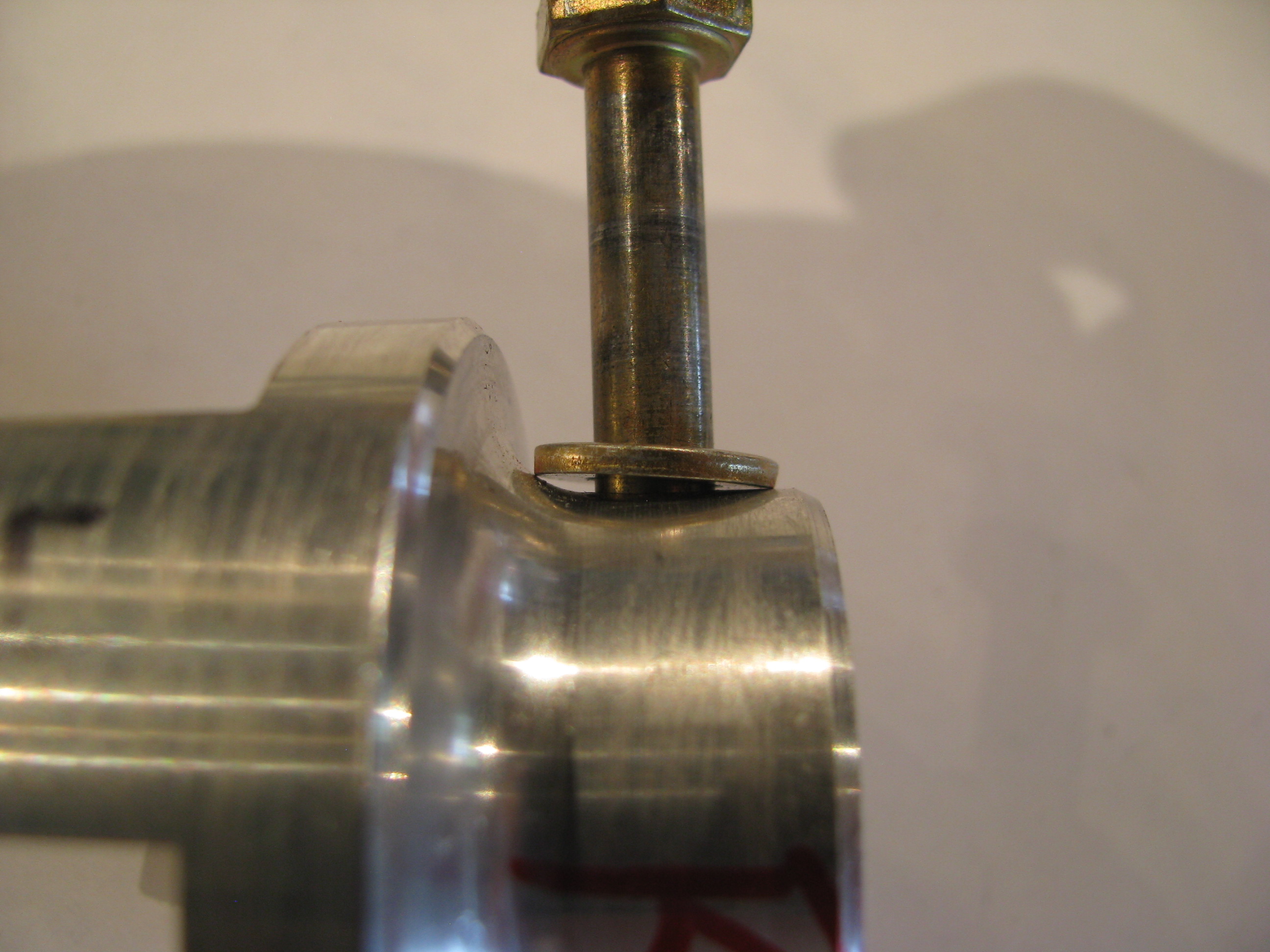
Because of the curved taper from the shaft collar to the dog face, the washer/bolt interferes with the curve.
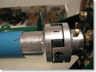
I could have filed an angle on the washers, but that seemed a little inelegant, and I DO have this wonderful mill.

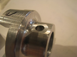
Like all the machining I have done, clamping aligning and measuring is 90% of the time and the actual metal cutting takes about 12 seconds.
I was careful to not take off very much. This is a jumbo-thick part, so I am sure it is plenty strong, but I still did not want to cut full width flats as that would have eaten quite a bit more metal.
Because of the curved taper from the shaft collar to the dog face, the washer/bolt interferes with the curve.

I could have filed an angle on the washers, but that seemed a little inelegant, and I DO have this wonderful mill.
Like all the machining I have done, clamping aligning and measuring is 90% of the time and the actual metal cutting takes about 12 seconds.
I was careful to not take off very much. This is a jumbo-thick part, so I am sure it is plenty strong, but I still did not want to cut full width flats as that would have eaten quite a bit more metal.
Bracket Repair
06/08/12 14:12 Filed in: All
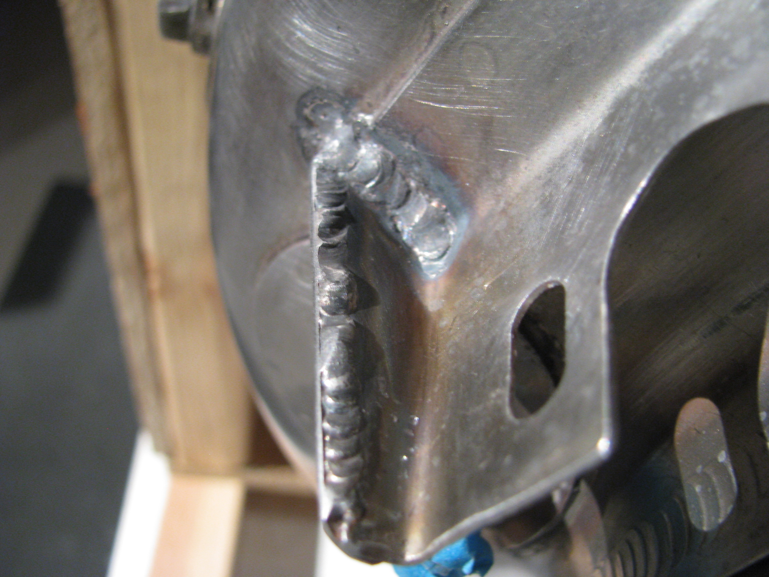
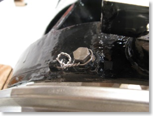
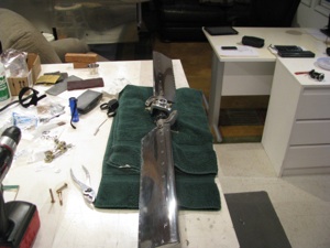
Picked up my turbine from my mechanic. The crack on the manifold bracket was welded with a little doubler to strengthen it. Much stronger and straighter now.
Initial Panel Fabrication
06/03/12 16:31 Filed in: All
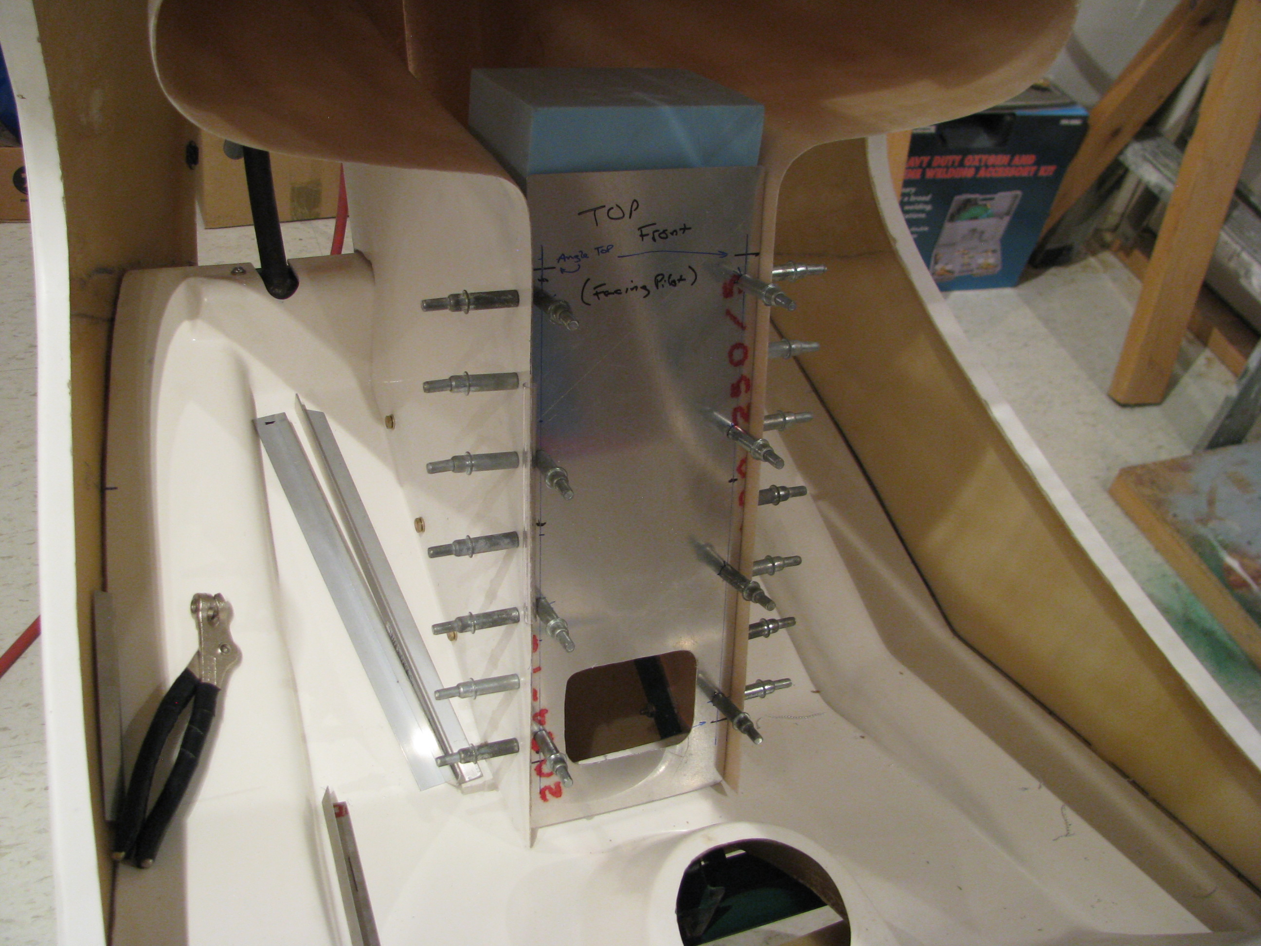
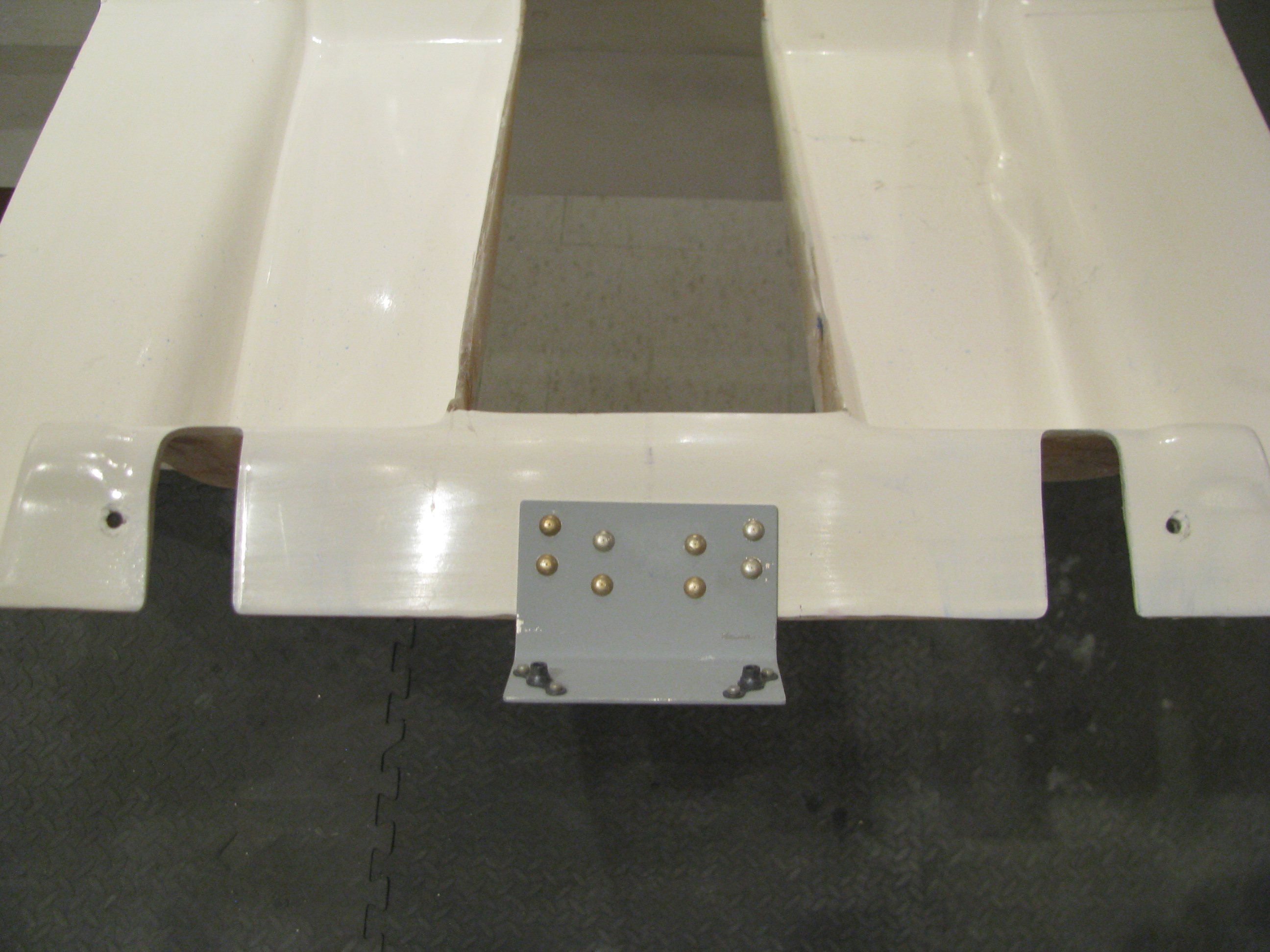
Fitting the lower instrument panel. The initial fitup is with a sacrificial aluminum sheet. Once everything is placed I will use it as a template to transfer the holes to the actual sheet to be used.
The hole is cut so I can get my hand in there and place a bracket on the pan to affix the panel on the lower edge, which should definitely strengthen things up. Screwing it in will be a pain since the cyclic riser is in the way, but not too bad with a 90 degree phillips.
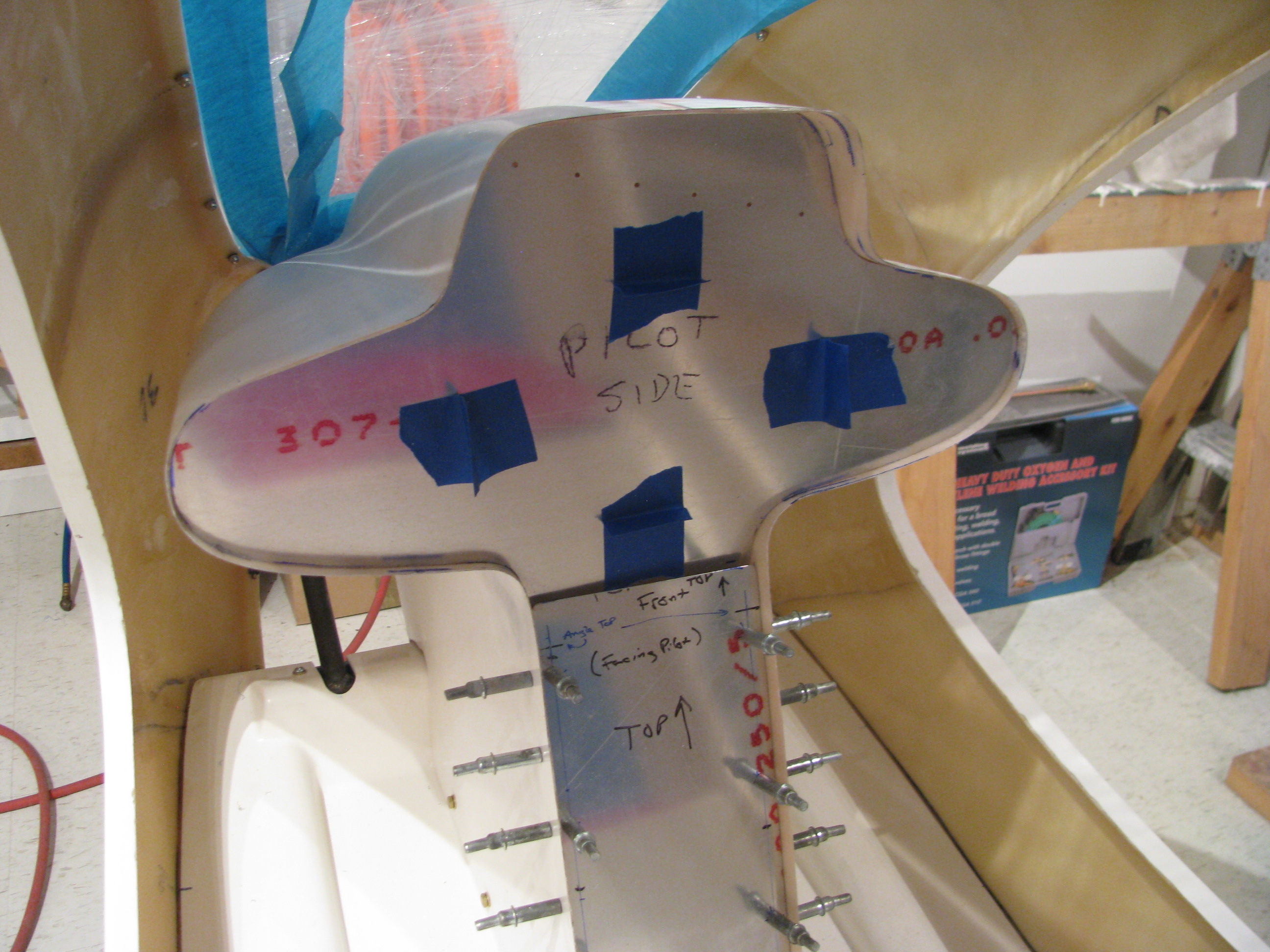
Initial cutout of the upper. This again is a sacrificial piece of aluminum. I wanted to see where I stand before messing around with the shape.
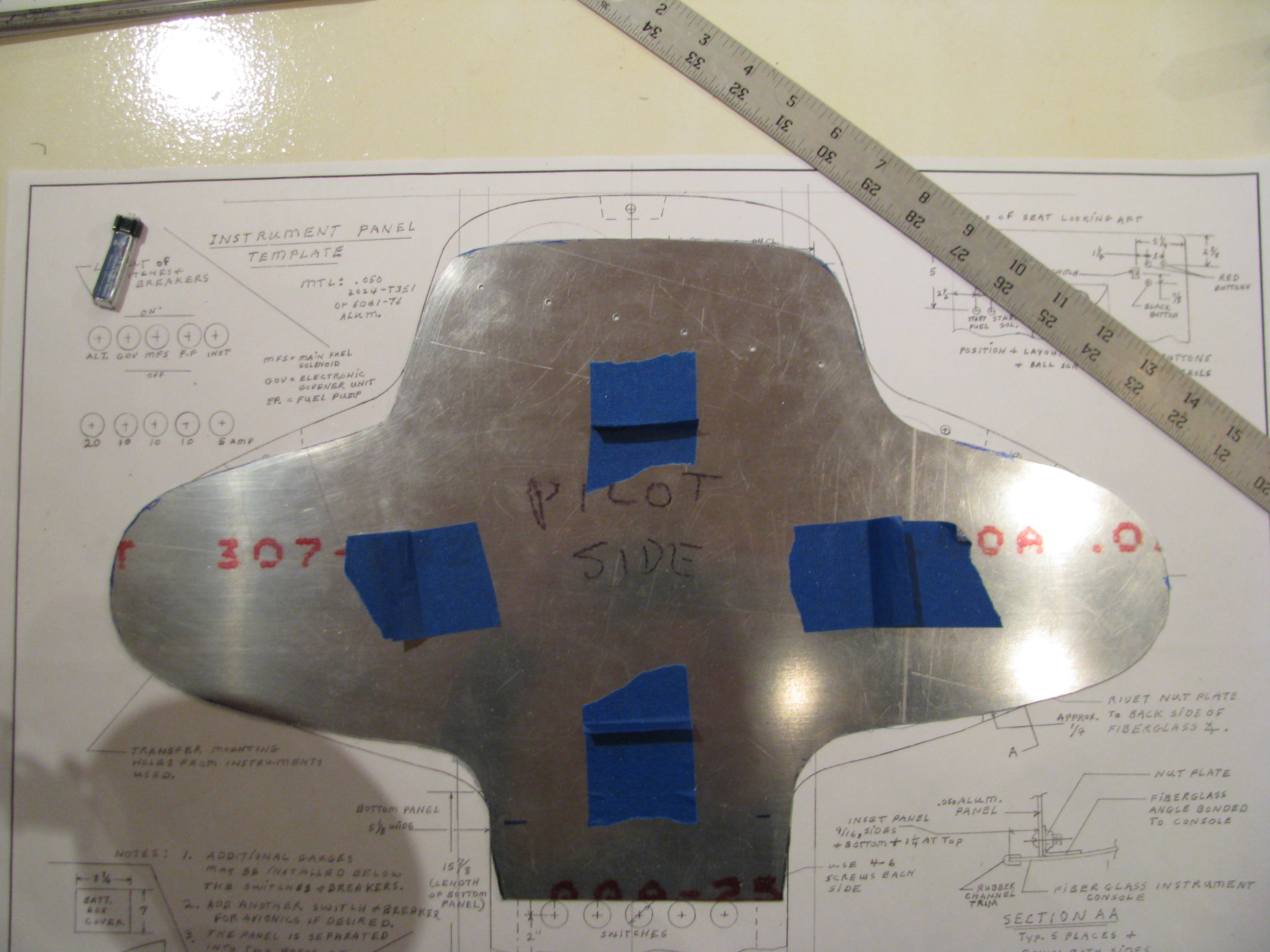
Obviously the upper instrument pod is flatter and narrower than the specified dimensions by a lot.
The drawing sheet shows an 18 3/8” width at the widest point. I am seeing almost an inch wider and and inch and a half “shorter” from the bottom to the top. I am going to have to shim the side lobes to get more vertical space and hopefully narrow it up some.
I’ll use some blue foam blocks to push the upper section up, but probably won’t get to the specified dimensions without really distorting the pod from it’s relaxed state, which I don’t want to do. The primary requirement is that the side lobes be large enough for a 3-1/8” instrument. Once that is close enough for me I will glass in the foam spacer blocks.
Engine Stand
05/28/12 14:10 Filed in: All

Not much happening here. I built a dolly to carry the turbine out so I can take it to be welded on the fuel manifold bracket.
Received Fixed Bearing
05/26/12 13:36 Filed in: All
After more than a month I received my rebuilt tail rotor slider bearing from Eagle. Smooth. I can now finish up the tail rotor assembly.
POR15 Engine Painting
05/06/12 14:07 Filed in: All

The engine has been painted with POR-15 gloss black. This stuff is really shiny and flows out oh so slowly.
The most time-consuming part was masking all the heads of the allen head bolts. That took forever and then was painful to remove as the POR really grabbed the tape.
I had to touch it up with an artists brush after removing the masking tape. but it’s finally done.
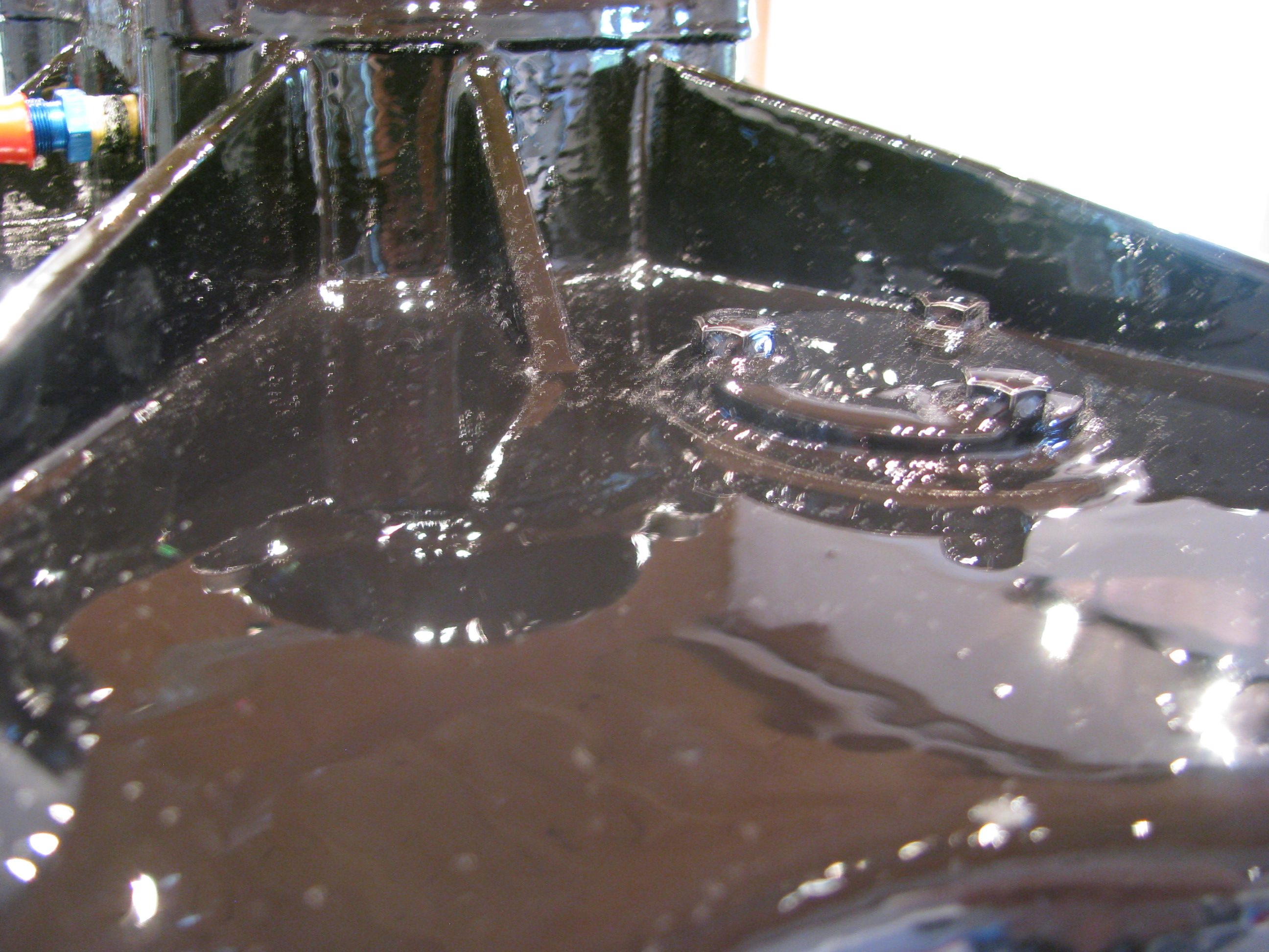
The POR-15 flows out very slowly. I can’t believe this is a brushed-on finish.
Now this is a rough casting, so I was not expecting a show quality finish, and it isn’t, but overall I a pleased with the outcome. The paint flowed out evenly and the brush marks disappeared.
It appears to be a thick, tough finish.
Cracked Manifold Bracket
04/30/12 14:05 Filed in: All
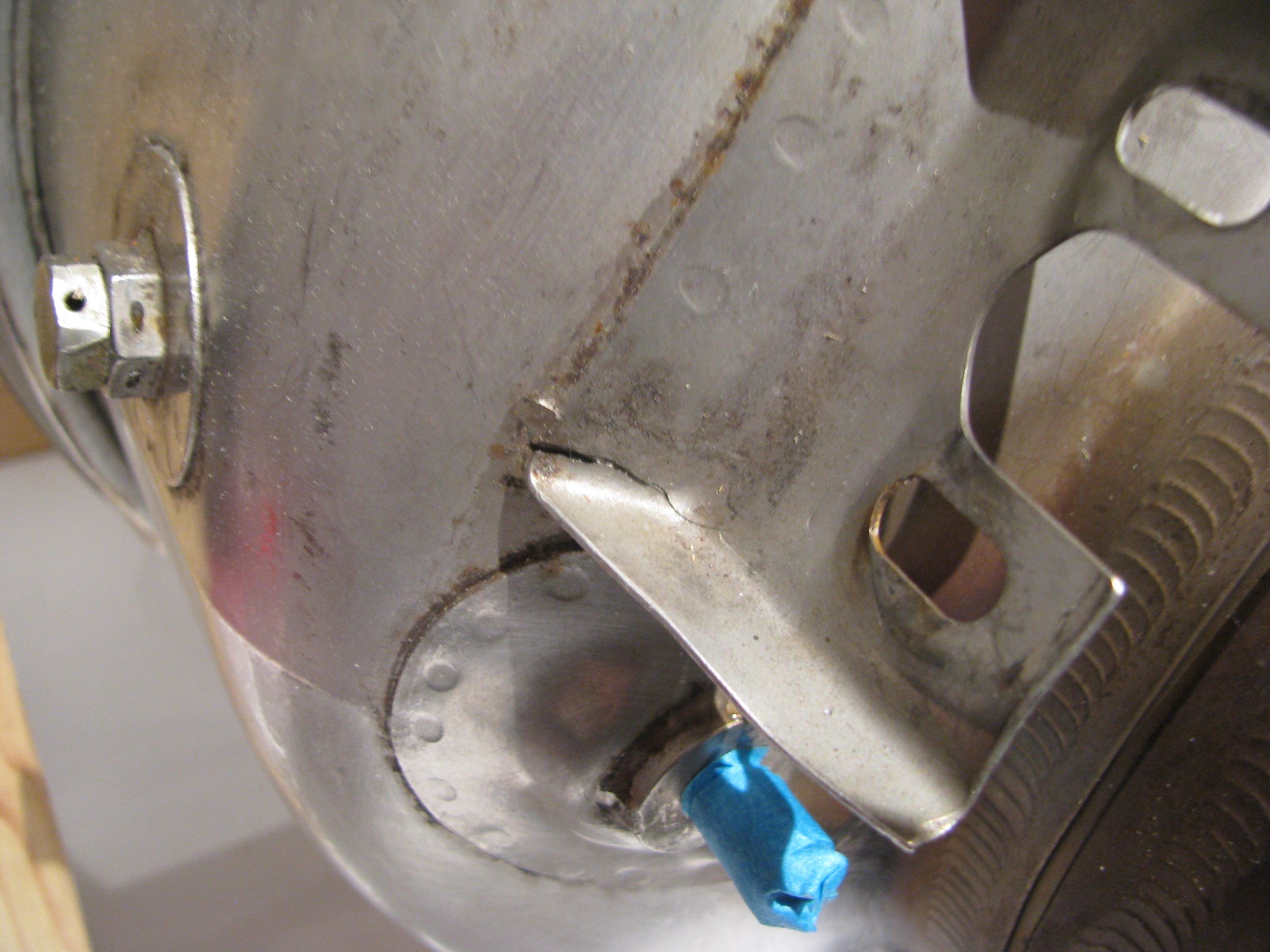
One flaw I noticed was that the bracket on which the fuel distribution manifold is mounted is cracked. You can just see the crack in the bent angle of the bracket. I will have to have this rewelded before the engine goes in. It really wasn’t evident until the manifold was removed, so I can’t really get down on Eagle for this. I will truck the engine over to my airplane mechanics to be repaired before starting re-assembly.
Paint Planning
04/14/12 17:40 Filed in: All
Against all recommendations and commonly accepted practice, I DO plan on painting this thing myself. The frame is already powder coated GREEN, of all things. I did not choose it, the original kit purchaser did, but have decided to live with it since changing would be a lot of work and $$$. The powder coat is in pretty good shape and I found exact color-matched touch up paint, so that’s decided.
Now maybe because I’ve been staring at it in the raw gelcoat for so long, the white has kind of grown on me. Green frame, white fins and cabin with a flat black interior (low reflections). That’s the working direction. Basic, not gaudy. Works with the green and won’t offend anyone, nor will it impress with any great inspiration or creativity either. I should be able to pull this off myself since there are no swoopy transitions and multi-color blends. I may add some trim colors, but only later and maybe with vinyl graphics.
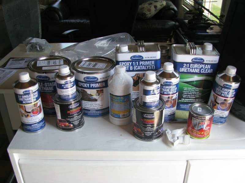
Does the table at the top look impressive? It should. That’s $450 worth of painting chemicals. I am quite sure I bought way too much flat black and not enough white, but we’ll see. Eastwood had the stuff to me within 4 days and I didn’t pay for any expedites (every can was dented, but not breached).
Now maybe because I’ve been staring at it in the raw gelcoat for so long, the white has kind of grown on me. Green frame, white fins and cabin with a flat black interior (low reflections). That’s the working direction. Basic, not gaudy. Works with the green and won’t offend anyone, nor will it impress with any great inspiration or creativity either. I should be able to pull this off myself since there are no swoopy transitions and multi-color blends. I may add some trim colors, but only later and maybe with vinyl graphics.
Does the table at the top look impressive? It should. That’s $450 worth of painting chemicals. I am quite sure I bought way too much flat black and not enough white, but we’ll see. Eastwood had the stuff to me within 4 days and I didn’t pay for any expedites (every can was dented, but not breached).
Instrument Panel Planning & Fitting
04/08/12 14:40 Filed in: All
Instruments planned for the upper pod:
TOP ROW: Airspeed Indicator, Rotor RPM
MIDDLE ROW: Altitude, temp gauges, Flow Level/Flow, Vertical Speed
BOTTOM: GPS/COMM , Transponder, Compass
Lower Section: Switches, Engine RPM, Breakers
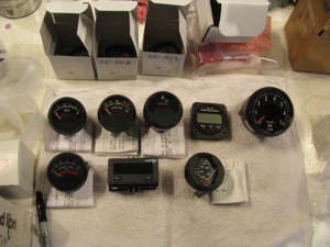
All but one of these are provided with the kit; Voltage, Transmission Temp, Hour Meter, Flow Flow (I supplied), Tachometer, Turbine Exhaust Temp, Engine Tach, and Oil Temp and Pressure.
Leftover from my RV8A project is a Garmin GNC300XL GPS/COMM and a GTX327 transponder.
Left to purchase is an AS indicator, Altimeter, and VSI.
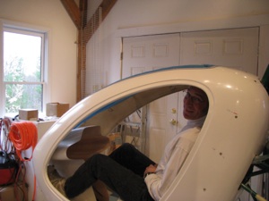
Checking the instrument pod positioning. And... making helicopter noises. One of those FAA “builder” pictures.

I ordered a Falcon 0-120MPH airspeed indicator and decided to try something a little different for the altitude. I ordered an MGL combined digital Altimeter and VSI.
Unlike fixed wing flying, I find myself really only relying on the altimeter around airports and airspace in a helicopter. You’re flying is so low and slow that visual reference for altitude is pretty accurate. The VSI bar looks quite attention-getting, which is the important thing. We’ll see how this works.
Stripped Turbine
04/08/12 14:00 Filed in: All
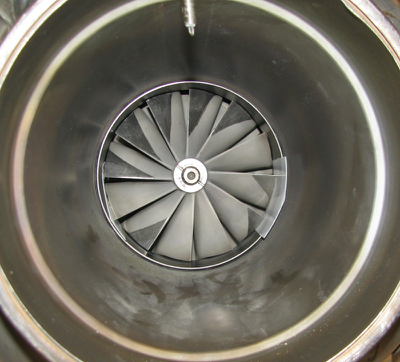
Nearly fully denuded. I am going to remove the fuel injection manifold as there is quite a bit of corrosion in the area where the tailpipe clamp goes. Mainly cosmetic, but it looks pretty bad. It will also allow for more shining up of the burner can. 10 minutes on that top section and it looks OK.
I’ve ordered some black POR-15 to paint everything but the burner can. I would have used clear, but that center section is so discolored that there is no way I could get it looking good.
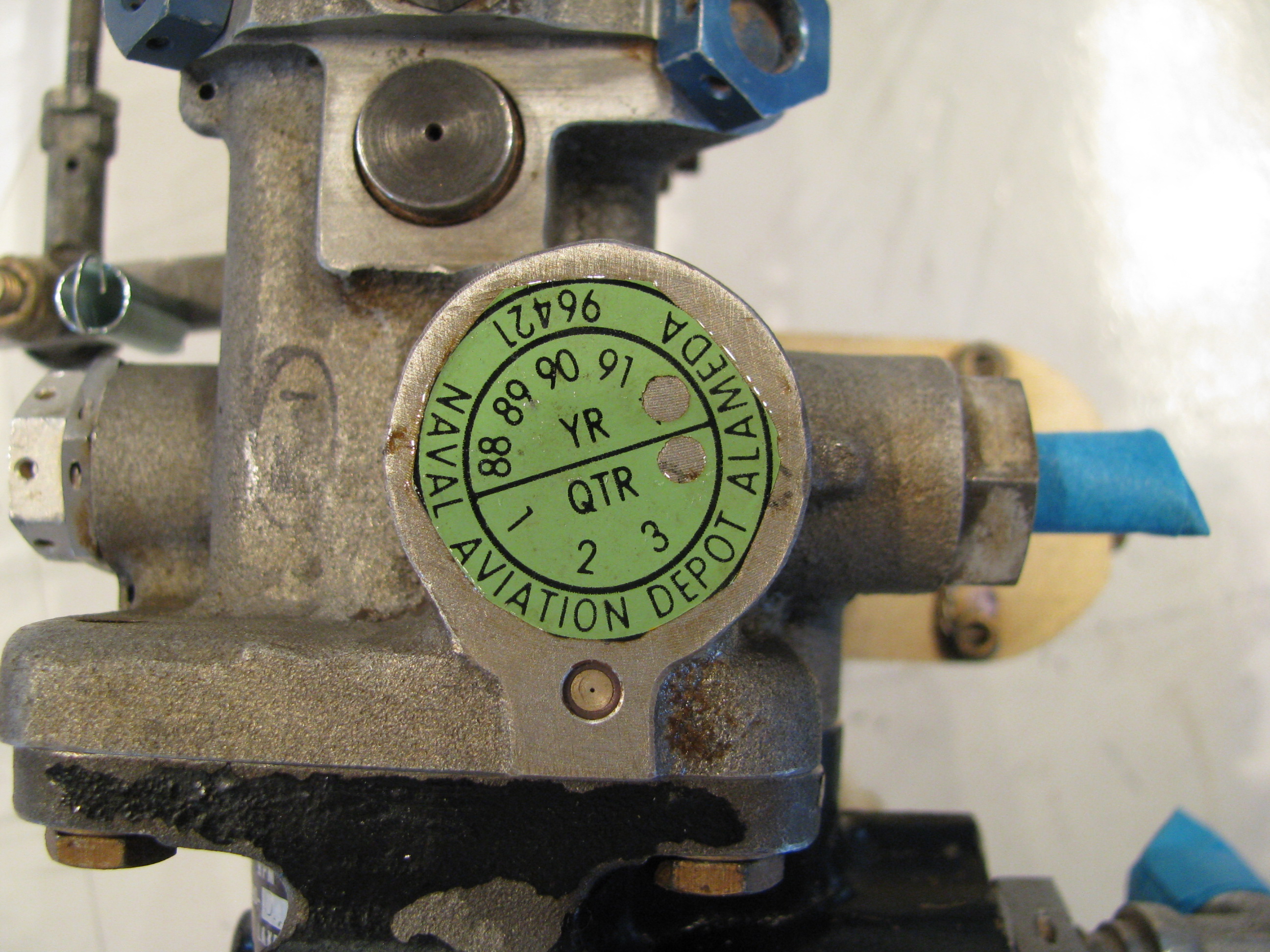
A clue as to the past life of this turbine.
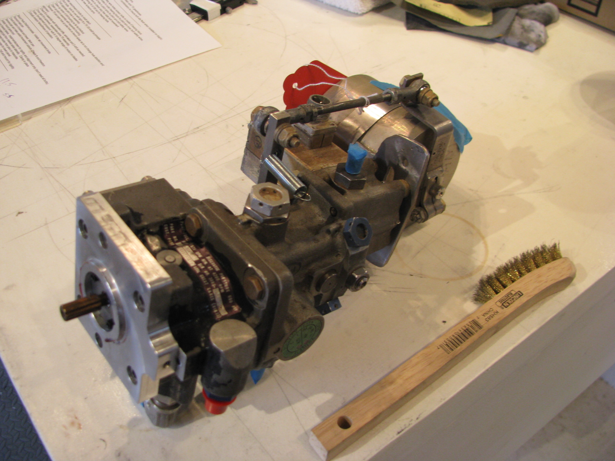
This is the fuel pump/control unit. That arm on the top is the infamous “delicate” throttle control arm. It is kind wimpy looking, but not tragically so. The surprising part is that the full travel from stop to stop is only about half an inch.
Though it is looks pretty tired, I am going to resist the temptation to take it apart to clean and resurface it. I’m quite sure that I would do more harm than good. It’ll just get cleaned and brushed off as an assembled unit, then reinstalled.
Speaking of more harm than good; BJ makes a point of having you make tick marks on the pulley and the mounting flange in the front of the gearbox to maintain alignment prior to removal. I did not realize that the conical center section is a piece separate from the pulley. I made my tick mark on the pulley, but when I pulled it off the shaft, the centering cone dropped out to the floor. I stared at it for 15 minutes to see if there was any hint of which position it was oriented in (1 of 6) by virtue of any witness marks on the mating surfaces, but could not. I will have to figure out where BJ was measuring when he said they were indexed to 0.003 to 0.005 of runout and remeasure to establish the orientation. Poop. This is my first mistake in a while caused by just not watching the videos closely enough.
Pedal Slots
03/31/12 22:54 Filed in: All
After not touching the body for a long time I am reassembling things so that I can fit the instrument pod.
Here I have cut the slots for the rudder pedals. Not trusting the scribe lines, I sort-of slid the pan on with the pedals in places so I could mark the locations for the cuts. Just using the scribed lines on the pan would have meant slots about half again wider than they really need to be since they were quite a bit offset from the actual pedal locations.
Turbine Install Start
03/31/12 13:49 Filed in: All
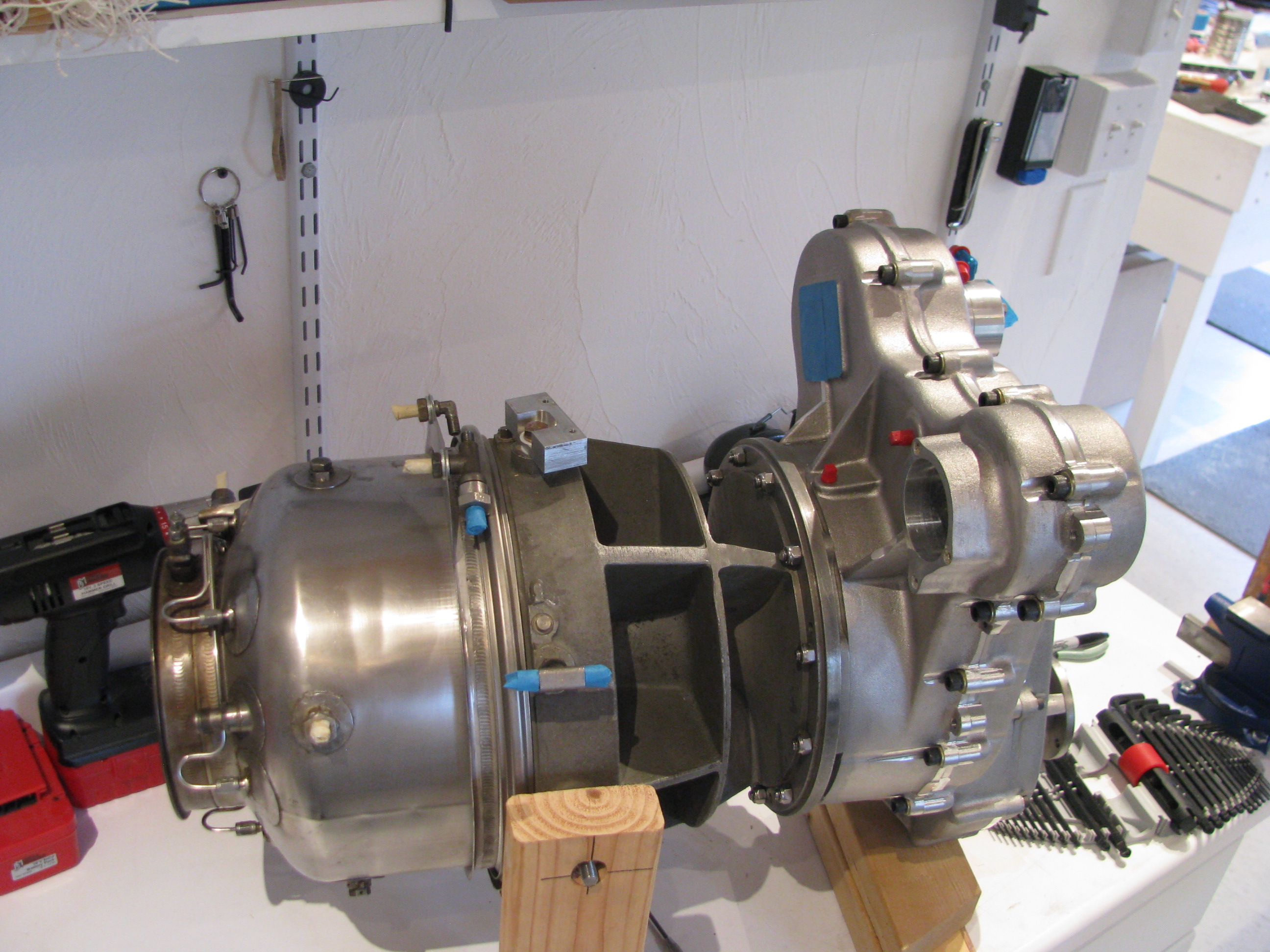
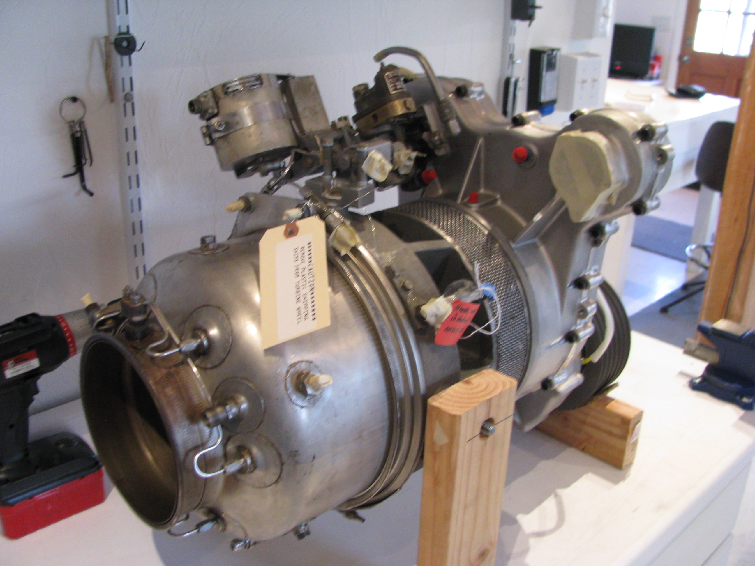
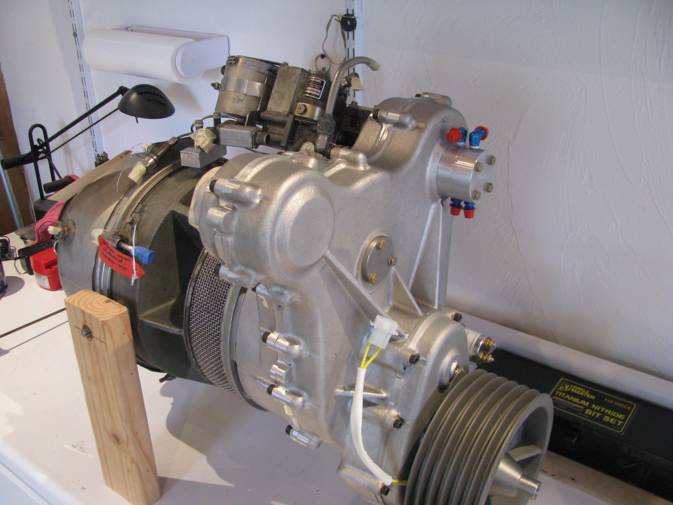
The Helicycle is powered by a Solar T62 turbine engine. It’s one of the primary attractions of this helicopter design. The T62 was designed as a ground power unit for the military for electrical generators and is used as the APU on a number of aircraft, including the CH47 Chinook.
In the Helicycle it is derated from its designed power output level of 160HP down to 90HP for reliability and longevity. Plenty of margin. Eagle R&D buys them surplus and refurbishes them including a teardown and dynamic balance.
As part of my effort to get multiple threads of effort going, I uncrated the engine and will begin tearing it apart in preparation for painting and mounting. You can see that I’ve started by removing the starter and a number of the fuel lines. Lots of pictures have been taken as each piece comes off and all the parts marked.
Mounting TR Assy
03/24/12 13:35 Filed in: All
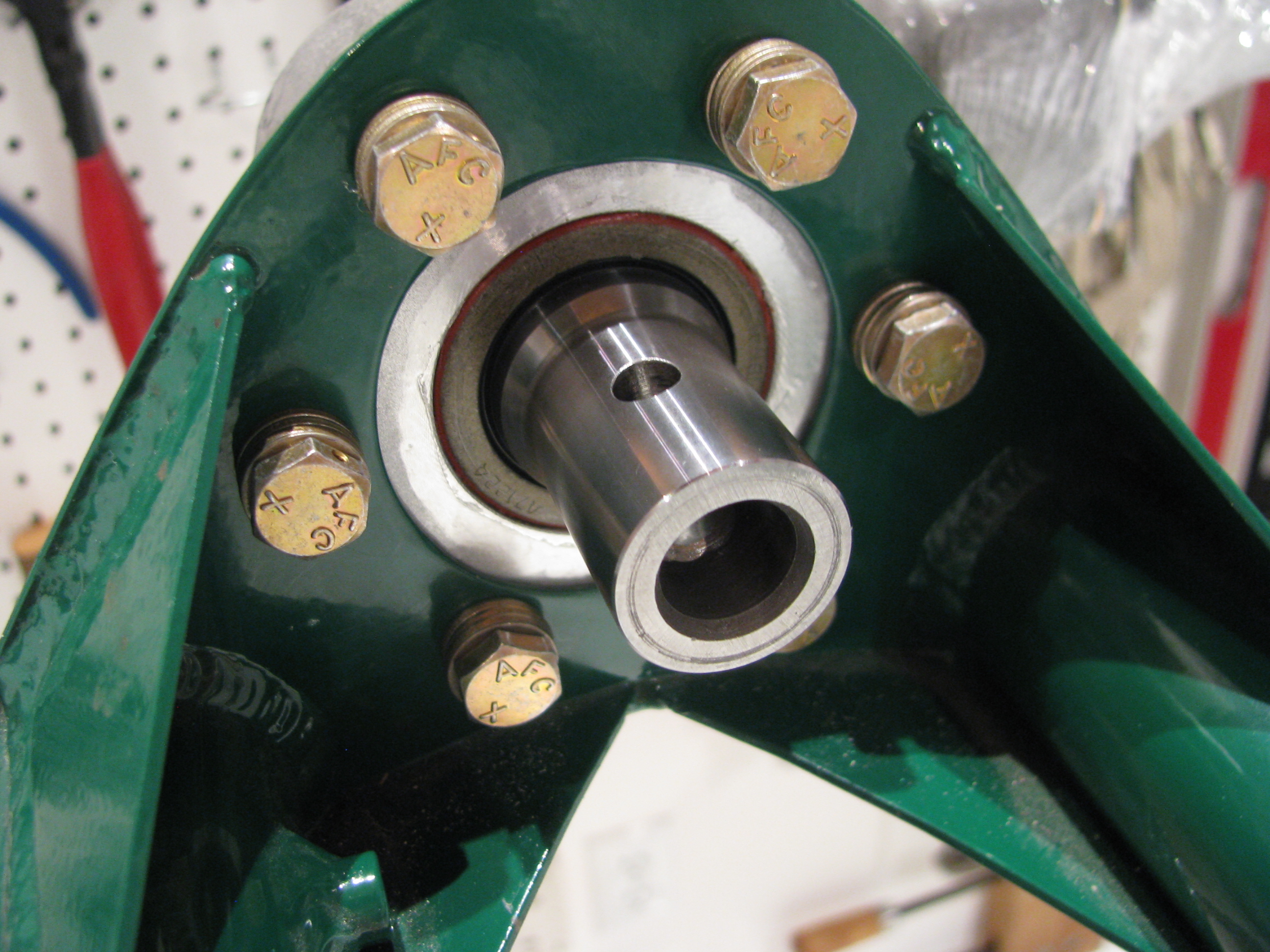
The actual kit I have (build 5) differs a little from what you see in the videos. I am assuming things have improved and the differences are due to improvements over time. One area is the tail rotor attachment. BJ makes reference to prick punch marks and precision fitment. In my case the yoke is drilled on one side only and is quite a bit undersize for an AN4 Bolt.
There are no matching prick punch marks.
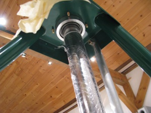
Here is the business end of the tail rotor hub looking into the yoke. The plastic piece in the center is the “flapping restraint” plug. The allen bolts have been drilled and safety wired.
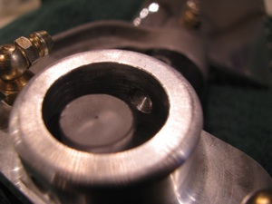
Looking into the yoke you can see the undrilled side. I searched the builders group and contacted Keith Southard whose kit was of the same vintage. He had the same situation and recommended a procedure for finish drilling this hole precisely with no slop.
The builder’s site is a great resource. Collectively there is a ton of information assembled and very knowledgable folks who are pretty responsive are active on it.

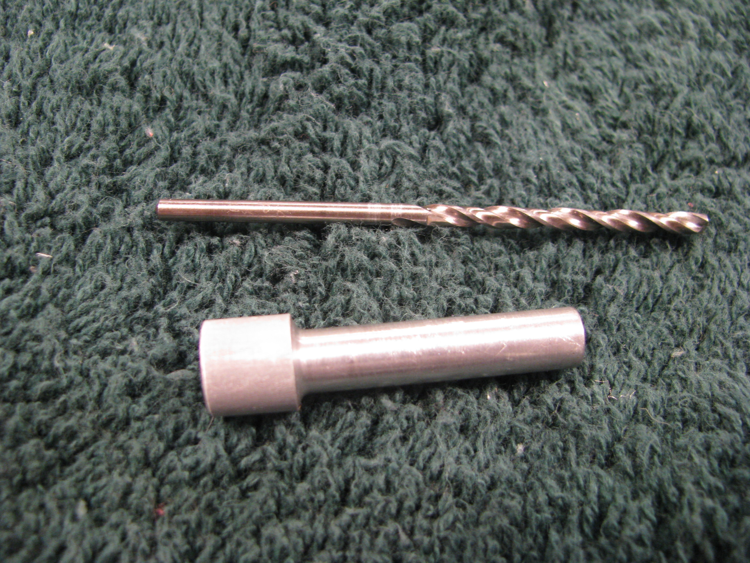
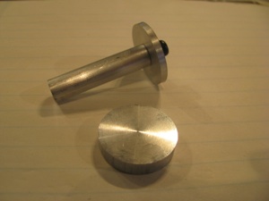
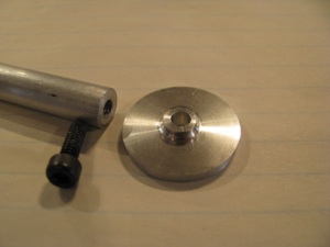
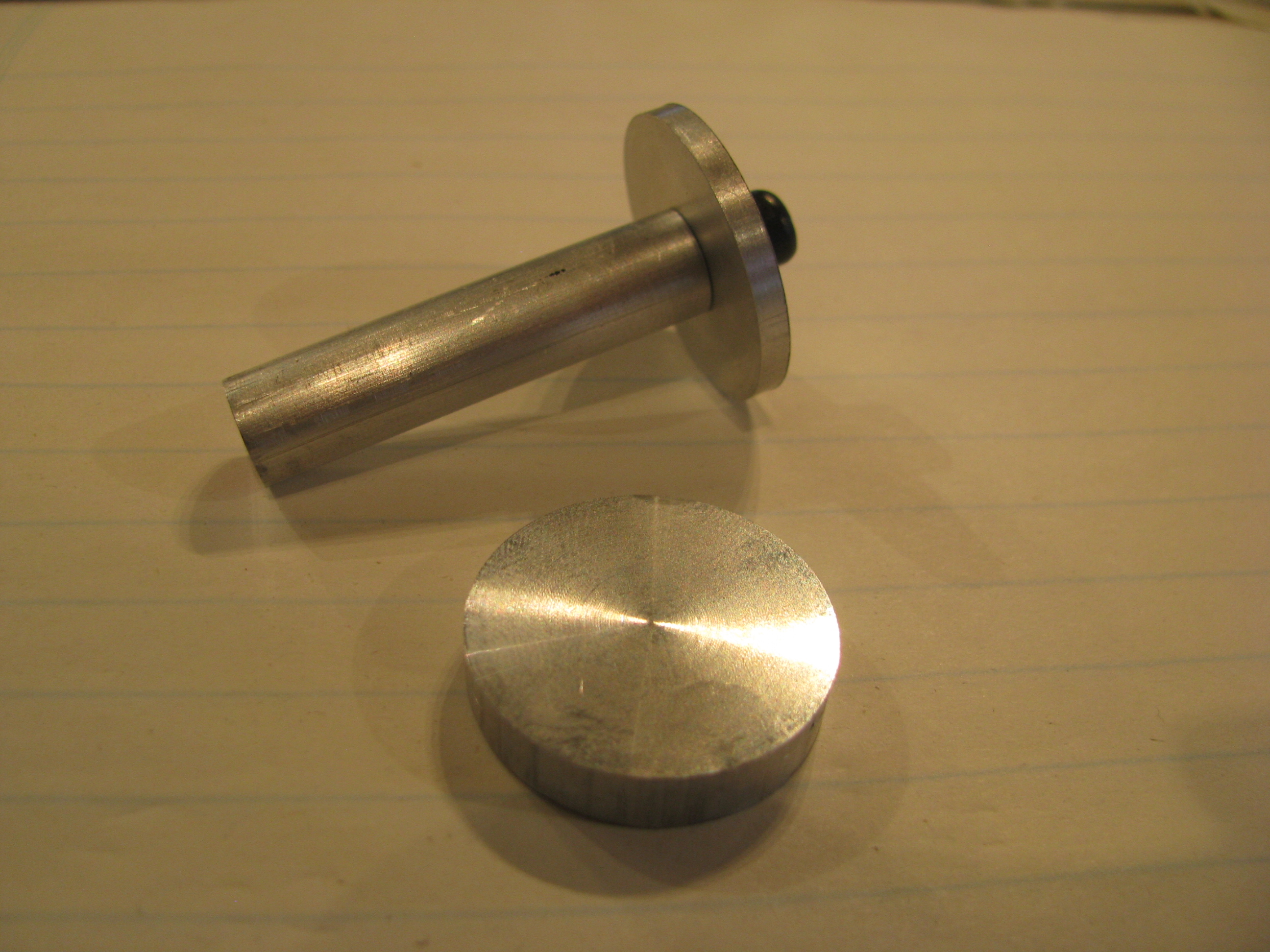
Start by making a drill bushing so a pilot can be drilled on the unfinished yoke side that will be perfectly centered. I chucked up an aluminum rod and lathed it down until it just barely and snugly fit in the hole on the drilled side. Then center bore a hole in the bushing for the pilot drill.
True to form, I messed up the first one, so I gave it a gentle chamfer and will use it as a drift to get everything lined up before employing the bushing and drilling for real.
The idea is that I will drill the far side yoke hole with the drill bushing in assembly and then open it up slowly.
The final couple of steps, including the reaming, if necessary, will be done in assembly so there is absolutely no slop. I will procure a collection of the correct length AN4 bolts including some “close fit” bolts so I have a selection to choose from . It is surprising how different bolts in the same bag can have different diameters by +/- a couple of a mils.
I also purchased kit of Nuvite Aluminum polish after reading Juan Rivera’s site and seeing his results. My plan is to polish the TR (no paint) as well as the TR drive shaft, main blades, and perhaps skids.
Now I am no expert. I just got the stuff. There are several different grades from the coarsest to the finest.
It doesn’t take a lot of brainpower, but it does take a lot of patience to get results. This is my first pass on the TR blades. It already looks better than anything I’ve ever polished before and I am sure I will repeat the sequence after all the handling of the TR is complete - so it will only get better.

Now I don’t think I’ll ever be as patient as Juan in getting the finish he shows on his web site, but it’ll still look good.
Polishing seems to have this bi-modal perception. You can get it looking shiny and very good. Stopping there would be fine. THEN , you decide to get mirror-like results and it’ll look like crap because once part of the surface shines up like a mirror, all the minor scratches and striations in the other areas become evident until the entire surface is perfect.
TR pitch link hardware. I blindly followed BJs instructions and cut 11/16 off the threads on the rod ends. You could probably leave another 1/16th or two on the ends (more threads to engage) as there is no way they will interfere with each other when screwed all the way in to the aluminum couplers.
I find that I am often making little sketches as I watch the videos (over and over) to have something to refer to in the shop.
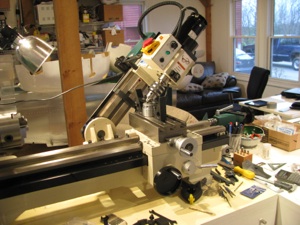
Drilling the safety wire holes in the slider would be a bit of a challenge without the mill. This is the first time I have ever angled the head over. The bearing block is then clamped to the surface in such a way that there is no side load on the bearing itself through the use of 3 large fender washers underneath the inner race.
As in most machining operations, the machine setup and work holding take 90% of the time. The actual metal cutting is but a few seconds.

The outer race is supported underneath with some blocks so there is no side load on the bearing. A center drill is absolutely necessary for its stiffness. Drill just deep enough so that a normal bit will not jump out.
The first hole was a mess, the second better, and by the fourth it was perfect. I’m sure my second helicopter would be absolute perfection.
TR pre-assembled. Couldn’t resist spinning it around.
When I did this, however, I noticed that the slider bearing was not spinning cleanly. The bearing is defective and “ticks” as it spins. You can feel the “hitches” when you spin it by hand on the bench. I called Blake and he agreed that it didn’t sound right. It’s on its way back to Eagle to have a new one pressed in.

There are no matching prick punch marks.
Here is the business end of the tail rotor hub looking into the yoke. The plastic piece in the center is the “flapping restraint” plug. The allen bolts have been drilled and safety wired.

Looking into the yoke you can see the undrilled side. I searched the builders group and contacted Keith Southard whose kit was of the same vintage. He had the same situation and recommended a procedure for finish drilling this hole precisely with no slop.
The builder’s site is a great resource. Collectively there is a ton of information assembled and very knowledgable folks who are pretty responsive are active on it.
Start by making a drill bushing so a pilot can be drilled on the unfinished yoke side that will be perfectly centered. I chucked up an aluminum rod and lathed it down until it just barely and snugly fit in the hole on the drilled side. Then center bore a hole in the bushing for the pilot drill.
True to form, I messed up the first one, so I gave it a gentle chamfer and will use it as a drift to get everything lined up before employing the bushing and drilling for real.
The idea is that I will drill the far side yoke hole with the drill bushing in assembly and then open it up slowly.
The final couple of steps, including the reaming, if necessary, will be done in assembly so there is absolutely no slop. I will procure a collection of the correct length AN4 bolts including some “close fit” bolts so I have a selection to choose from . It is surprising how different bolts in the same bag can have different diameters by +/- a couple of a mils.

I also purchased kit of Nuvite Aluminum polish after reading Juan Rivera’s site and seeing his results. My plan is to polish the TR (no paint) as well as the TR drive shaft, main blades, and perhaps skids.
Now I am no expert. I just got the stuff. There are several different grades from the coarsest to the finest.
It doesn’t take a lot of brainpower, but it does take a lot of patience to get results. This is my first pass on the TR blades. It already looks better than anything I’ve ever polished before and I am sure I will repeat the sequence after all the handling of the TR is complete - so it will only get better.
Now I don’t think I’ll ever be as patient as Juan in getting the finish he shows on his web site, but it’ll still look good.
Polishing seems to have this bi-modal perception. You can get it looking shiny and very good. Stopping there would be fine. THEN , you decide to get mirror-like results and it’ll look like crap because once part of the surface shines up like a mirror, all the minor scratches and striations in the other areas become evident until the entire surface is perfect.
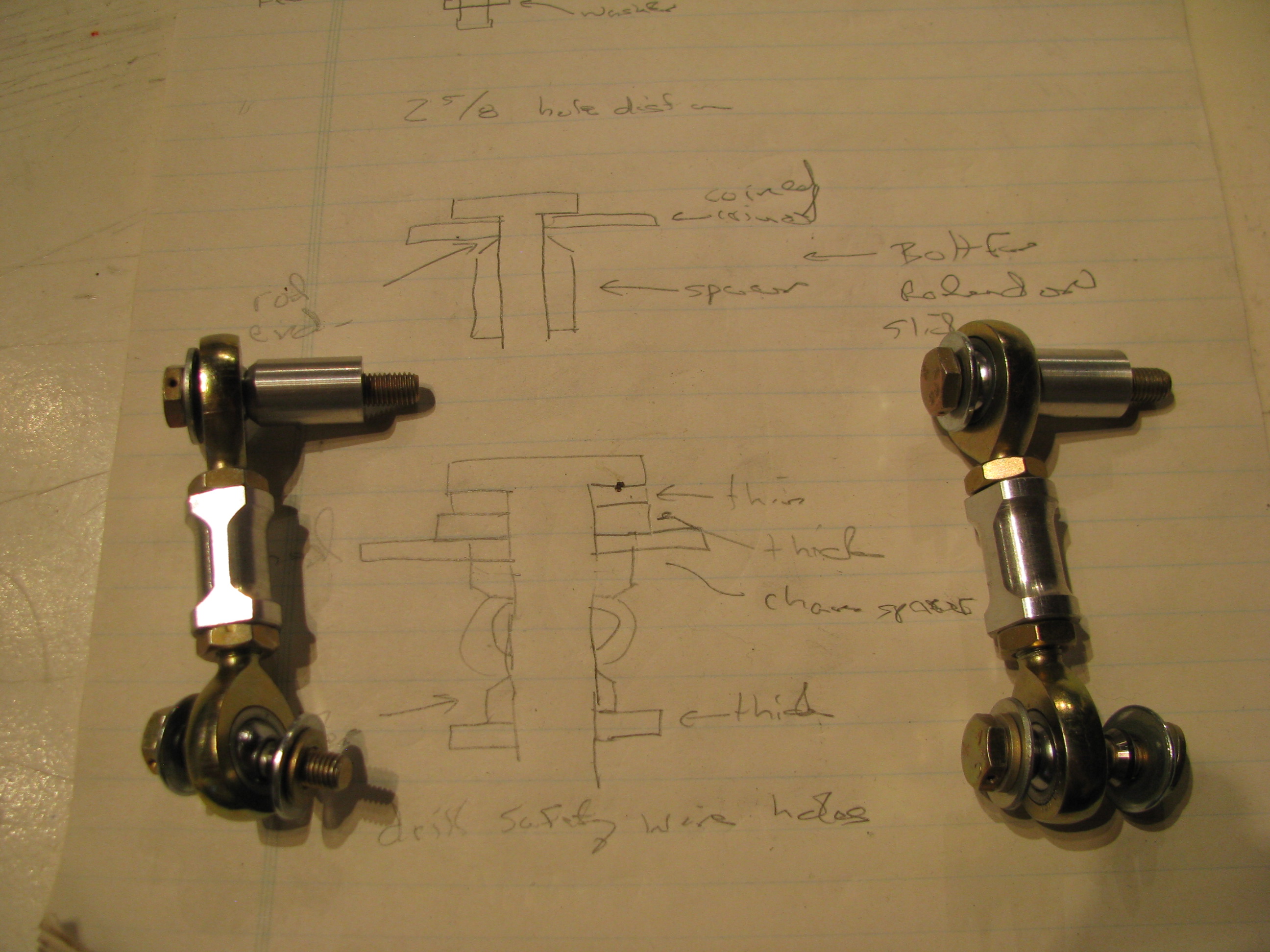
TR pitch link hardware. I blindly followed BJs instructions and cut 11/16 off the threads on the rod ends. You could probably leave another 1/16th or two on the ends (more threads to engage) as there is no way they will interfere with each other when screwed all the way in to the aluminum couplers.
I find that I am often making little sketches as I watch the videos (over and over) to have something to refer to in the shop.
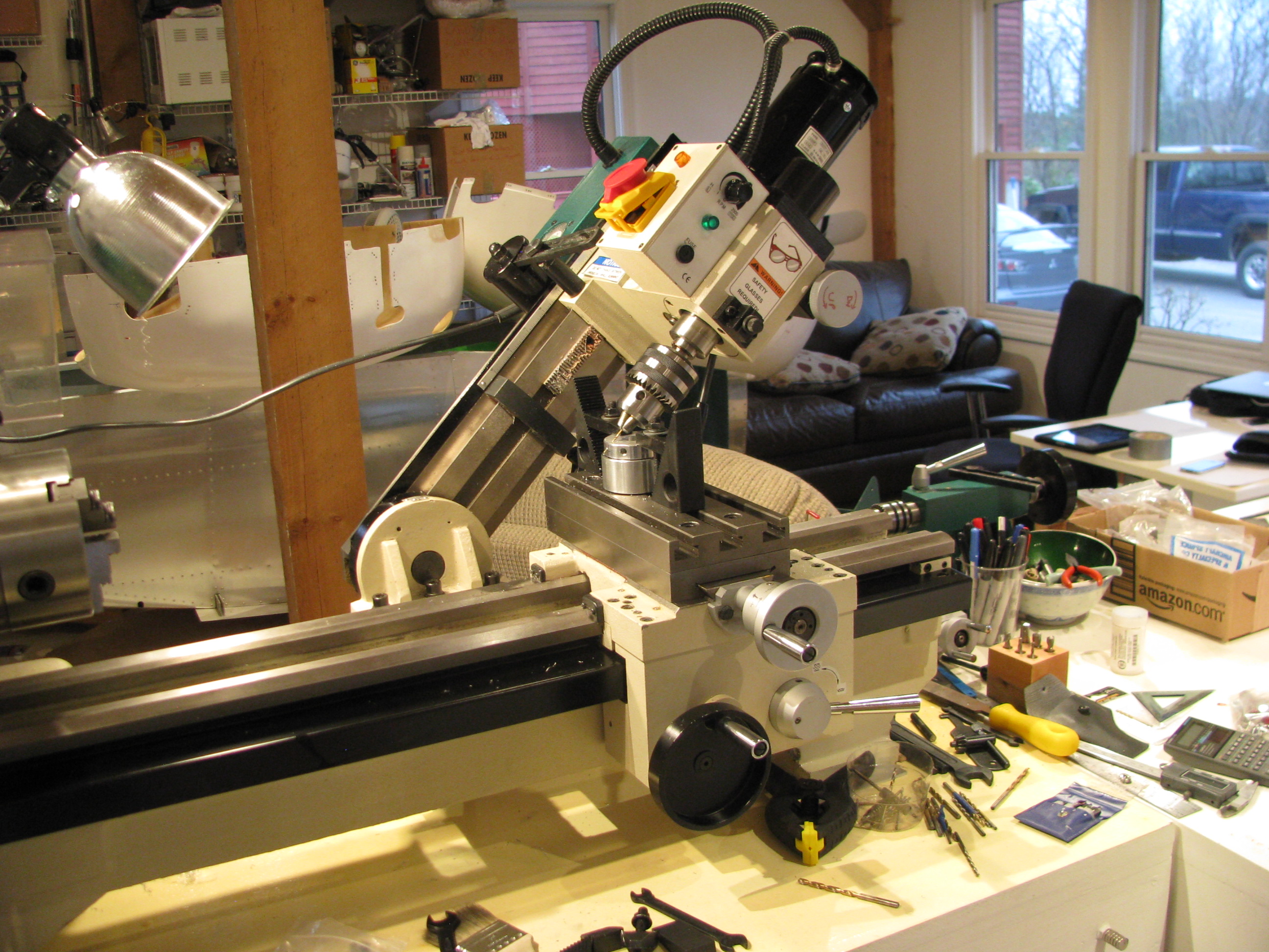
Drilling the safety wire holes in the slider would be a bit of a challenge without the mill. This is the first time I have ever angled the head over. The bearing block is then clamped to the surface in such a way that there is no side load on the bearing itself through the use of 3 large fender washers underneath the inner race.
As in most machining operations, the machine setup and work holding take 90% of the time. The actual metal cutting is but a few seconds.
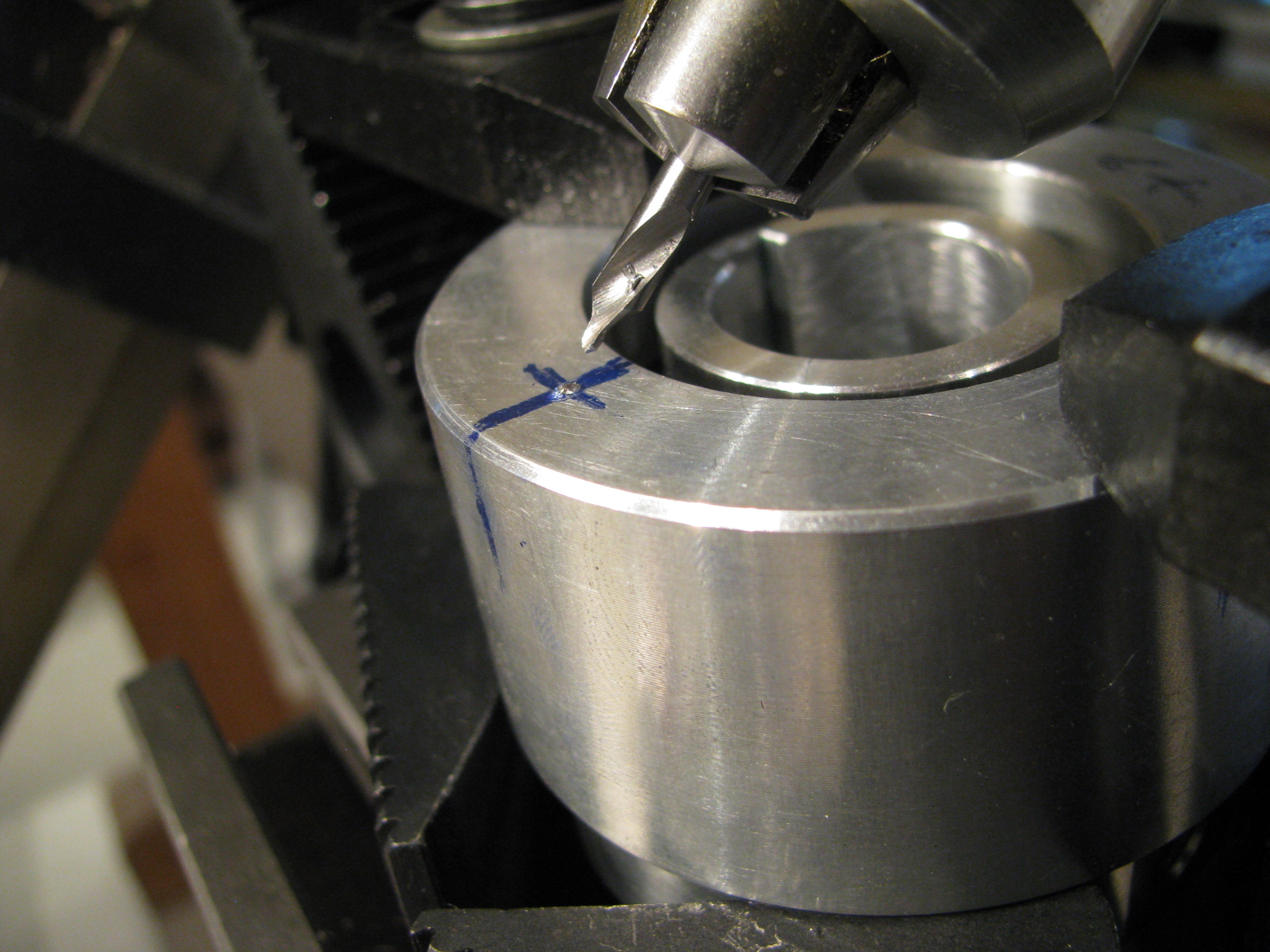
The outer race is supported underneath with some blocks so there is no side load on the bearing. A center drill is absolutely necessary for its stiffness. Drill just deep enough so that a normal bit will not jump out.
The first hole was a mess, the second better, and by the fourth it was perfect. I’m sure my second helicopter would be absolute perfection.

TR pre-assembled. Couldn’t resist spinning it around.
When I did this, however, I noticed that the slider bearing was not spinning cleanly. The bearing is defective and “ticks” as it spins. You can feel the “hitches” when you spin it by hand on the bench. I called Blake and he agreed that it didn’t sound right. It’s on its way back to Eagle to have a new one pressed in.
Tailrotor Start
03/17/12 11:48 Filed in: All
The pilot uses foot pedals to control the amount and direction of force exerted by the tail rotor to counter to the engine torque and thus control the direction the helicopter is pointing. Whenever the amount of power extracted from the engine is changed (climbing or descending), the amount of force needed from the tail rotor must be adjusted by the pilot to keep the helicopter pointing straight ahead.
The Helicycle kit comes with a largely assembled tail rotor since it is a very critical component and must be precisely constructed and balanced. My tasks consist of mounting, aligning and fabricating the control components.
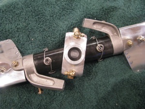
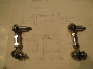
Start by fabricating the control arms from 1/8” aluminum. Cut out according to the drawing, drill appropriate holes and open up a slot for the slider studs to ride in. I don’t know why, but I did this the hard way by drilling starter holes and opening up the slot with a file. As soon as I started I kicked myself for not setting up the mill and machining out the slot.
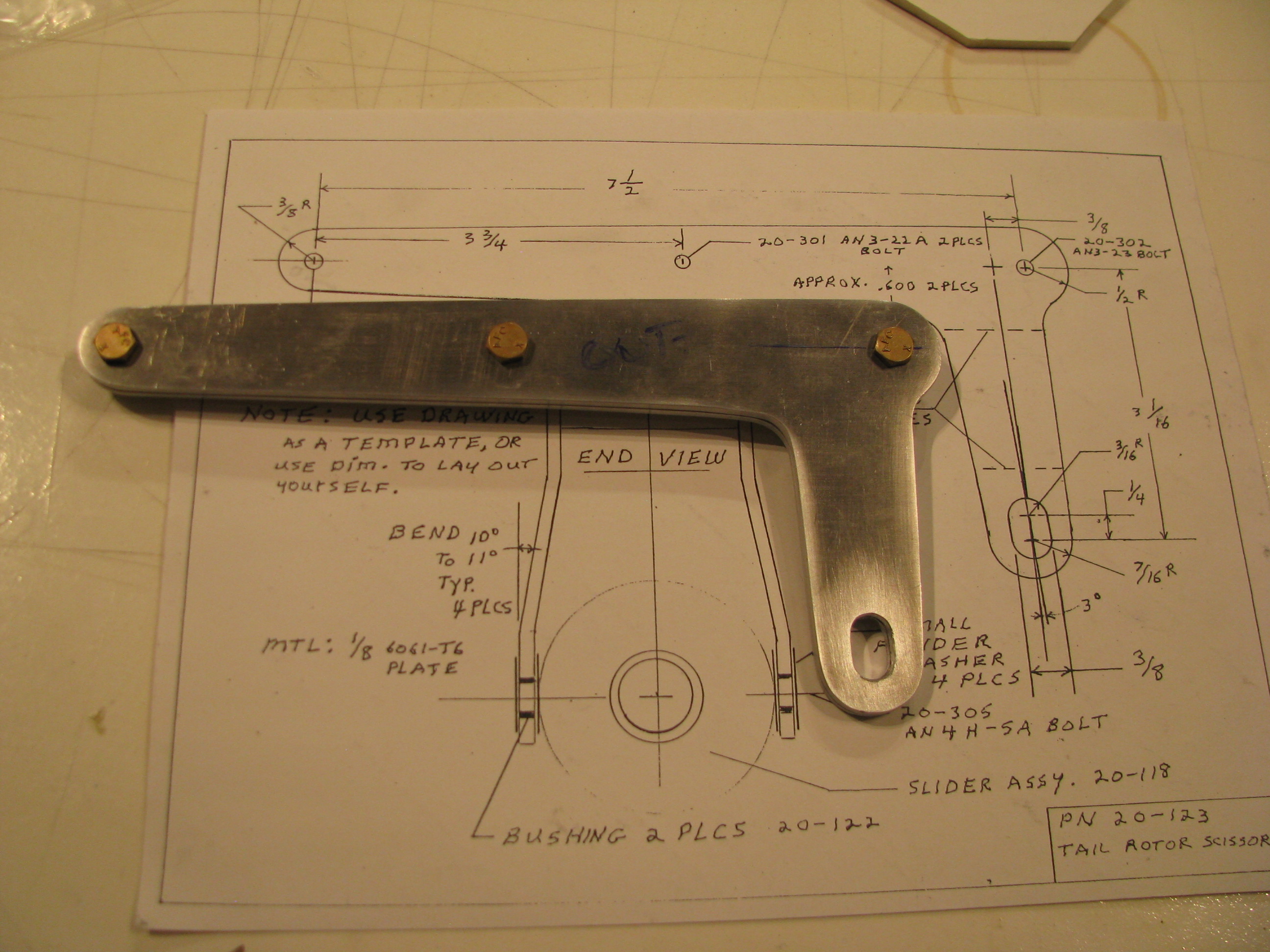
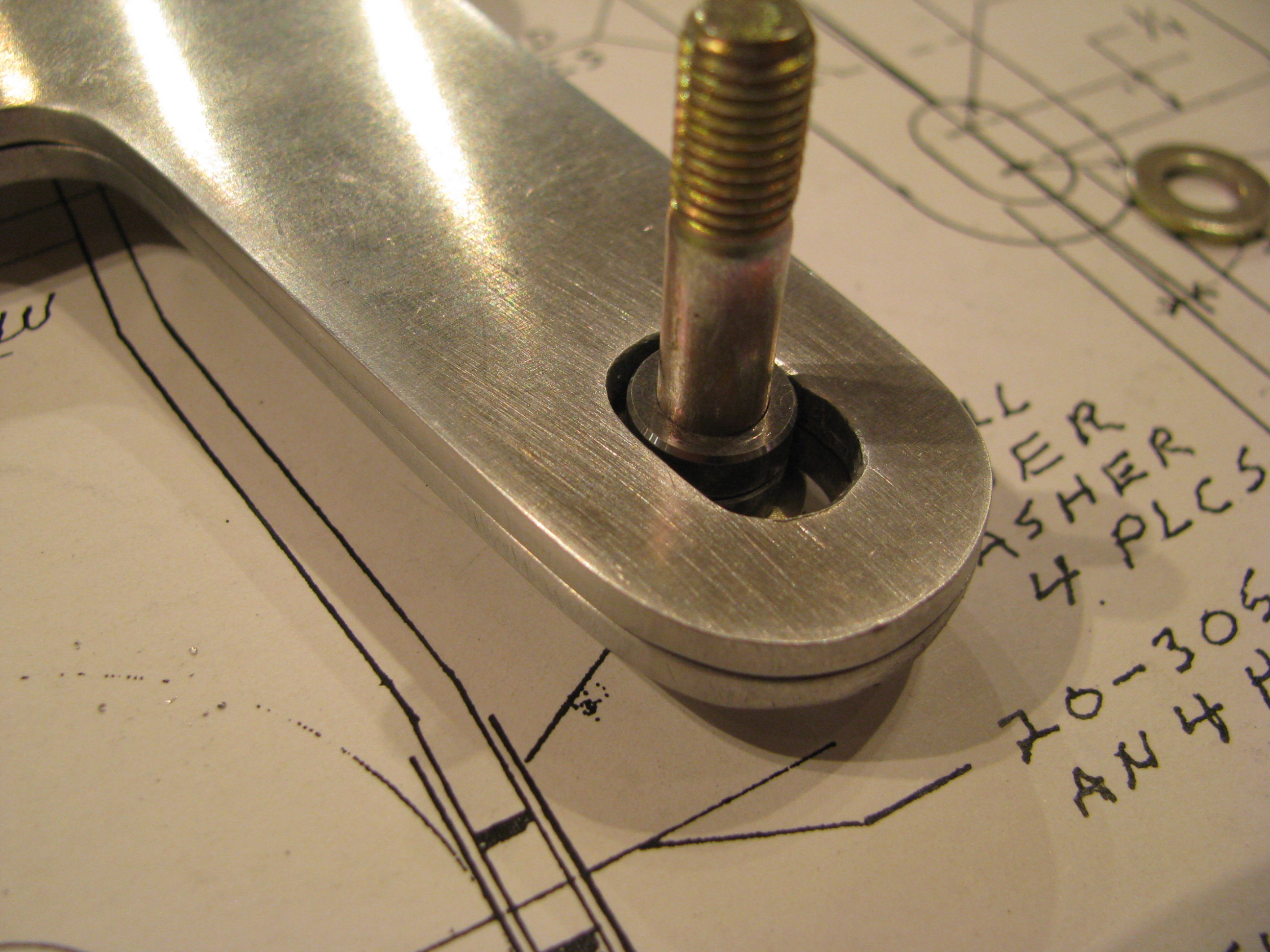
Doing it by hand is definitely not as precise. At one point in the slide there is a tiny bit of slop in the slot between the sleeved bolt and the aluminum. Probably 0.005” - Just enough to “tick” back and forth. I haven’t decided if this is enough to make me go back and fabricate new parts. I think I will see how much play there is when the whole thing is assembled. There are multiple bends and the slop may be “eaten” up by tolerances elsewhere. If there is any play when the tail rotor is installed I will re-fab the parts as I am guessing the tail rotor must be completely slop-free as it is subject to high frequency vibrations and much stress.
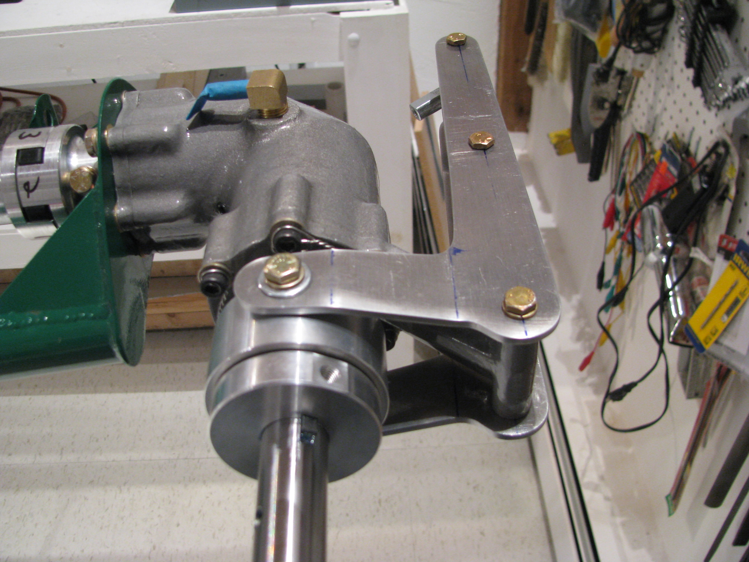
Bent and assembled the control arm scissors. Although it feels nice and snug, if you shwang the slider bearing back and forth you can feel a little play in the upper arm. I will fabricate new arms, but will use these for now for fitting and general assembly.
Bearing Block Mounting
03/12/12 11:42 Filed in: All
I have been poking along on a lot of different projects, but back to the tail rotor shaft. Each section is a little different. The following are the measurements I settled on TRShaftDims.pdf . The holes are all now drilled and I have put it all together and am starting the final alignment procedure.
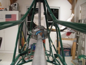


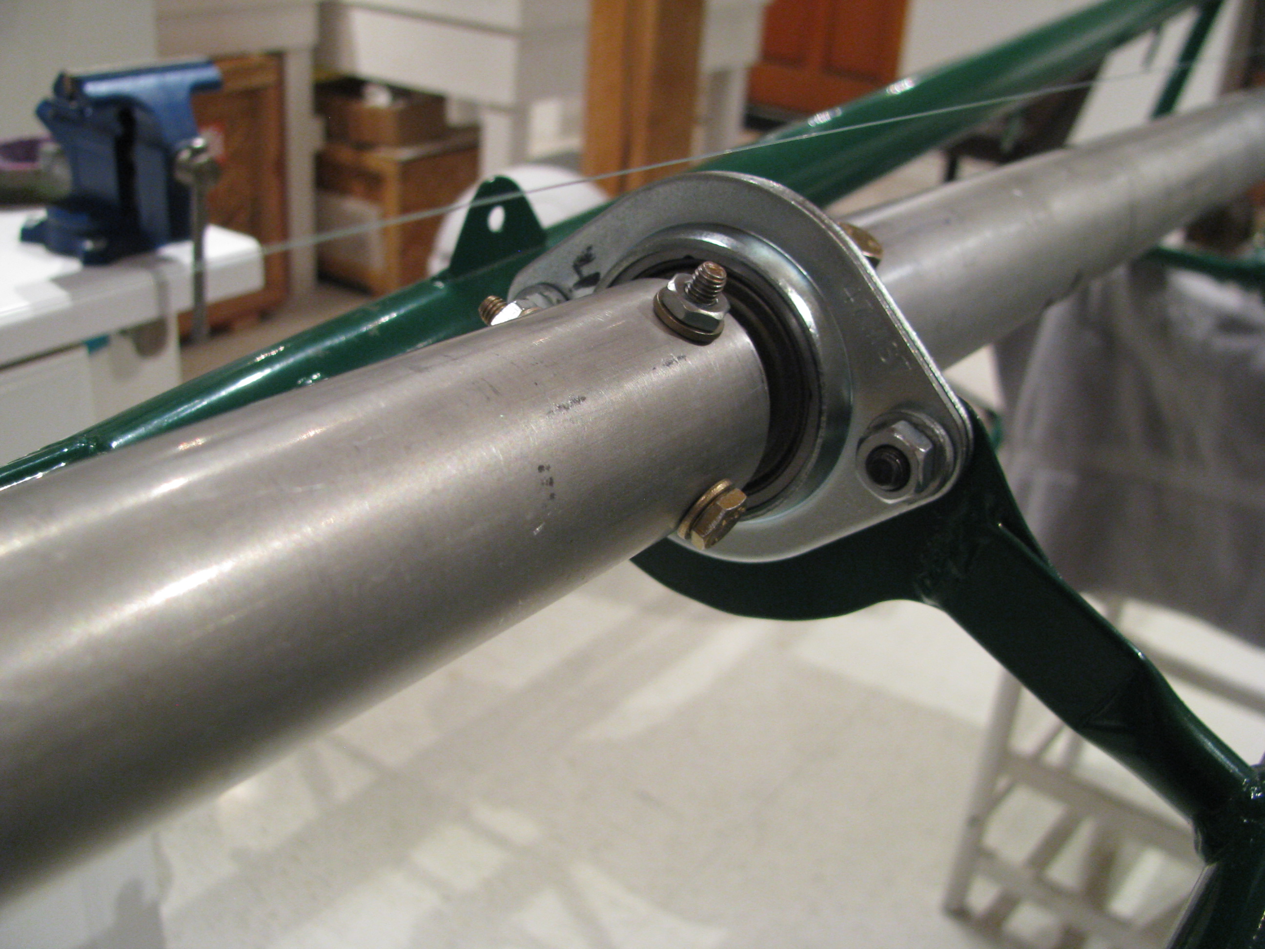
Almost done with gearboxes. Starting to look into the tail rotor.
More Heli-nerd stuff: I put together the entire tail rotor driveshaft, aligned it, and re-measured the clearance between the mating drive dog faces. Two different feeler gauges were used with different combinations of fingers to average out the errors, In all cases each measurement agreed within 0.001” of each other
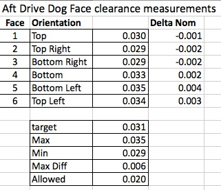
I am very pleased with the result at the rear. The shimming of the tail rotor gearbox is good and the drilling and fitting of the shafts didn’t change things that much. Cool. Everything is nicely centered on the nominal measurement and well under the allowed differential of 0.020”.
At the beginning of the video BJ gives you the target dimensions and at the end he sort of fudges and lets you know what you can really get away with. Happily I did not have to take advantage of the relaxed spec.
At the front shaft drive dog I got the following:
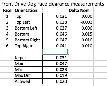
You can see that the front spacing is slightly larger and the differential is greater. The max differential is right at the (unrelaxed) spec limit. Not a lot can be done here since this is probably mostly due to the fact that the drive shaft is tilted up slightly from horizontal relative to the transmission and there is some built in twist to pre-compensate for the torquing of the frame under load. These should center out a little better when loaded, at least in the side-side differential department.
Overall I am pretty happy with this result as the distances are long and the potential for error is great. Just take your time and measure, measure, remeasure before drilling or cutting any metal.
Now, as with all other things on this machine, everything in this section gets pulled out and set aside until final assembly so I’ll be back to a stripped down frame again and my visitors will wonder if I am really doing anything other than napping in the shop.


Almost done with gearboxes. Starting to look into the tail rotor.
More Heli-nerd stuff: I put together the entire tail rotor driveshaft, aligned it, and re-measured the clearance between the mating drive dog faces. Two different feeler gauges were used with different combinations of fingers to average out the errors, In all cases each measurement agreed within 0.001” of each other
I am very pleased with the result at the rear. The shimming of the tail rotor gearbox is good and the drilling and fitting of the shafts didn’t change things that much. Cool. Everything is nicely centered on the nominal measurement and well under the allowed differential of 0.020”.
At the beginning of the video BJ gives you the target dimensions and at the end he sort of fudges and lets you know what you can really get away with. Happily I did not have to take advantage of the relaxed spec.
At the front shaft drive dog I got the following:
You can see that the front spacing is slightly larger and the differential is greater. The max differential is right at the (unrelaxed) spec limit. Not a lot can be done here since this is probably mostly due to the fact that the drive shaft is tilted up slightly from horizontal relative to the transmission and there is some built in twist to pre-compensate for the torquing of the frame under load. These should center out a little better when loaded, at least in the side-side differential department.
Overall I am pretty happy with this result as the distances are long and the potential for error is great. Just take your time and measure, measure, remeasure before drilling or cutting any metal.
Now, as with all other things on this machine, everything in this section gets pulled out and set aside until final assembly so I’ll be back to a stripped down frame again and my visitors will wonder if I am really doing anything other than napping in the shop.
Lee's first helicopter ride
03/04/12 11:13 Filed in: All
Shortly after getting my ticket, I took Lee up for a quick helicopter ride. She didn't like the fact that a minor shove would open the door, but overall had a good time. Linked below is an abbreviated video of that flight.
LEE's First Passenger Flight.
LEE's First Passenger Flight.
Laser Measure TR Shaft
02/17/12 11:39 Filed in: All
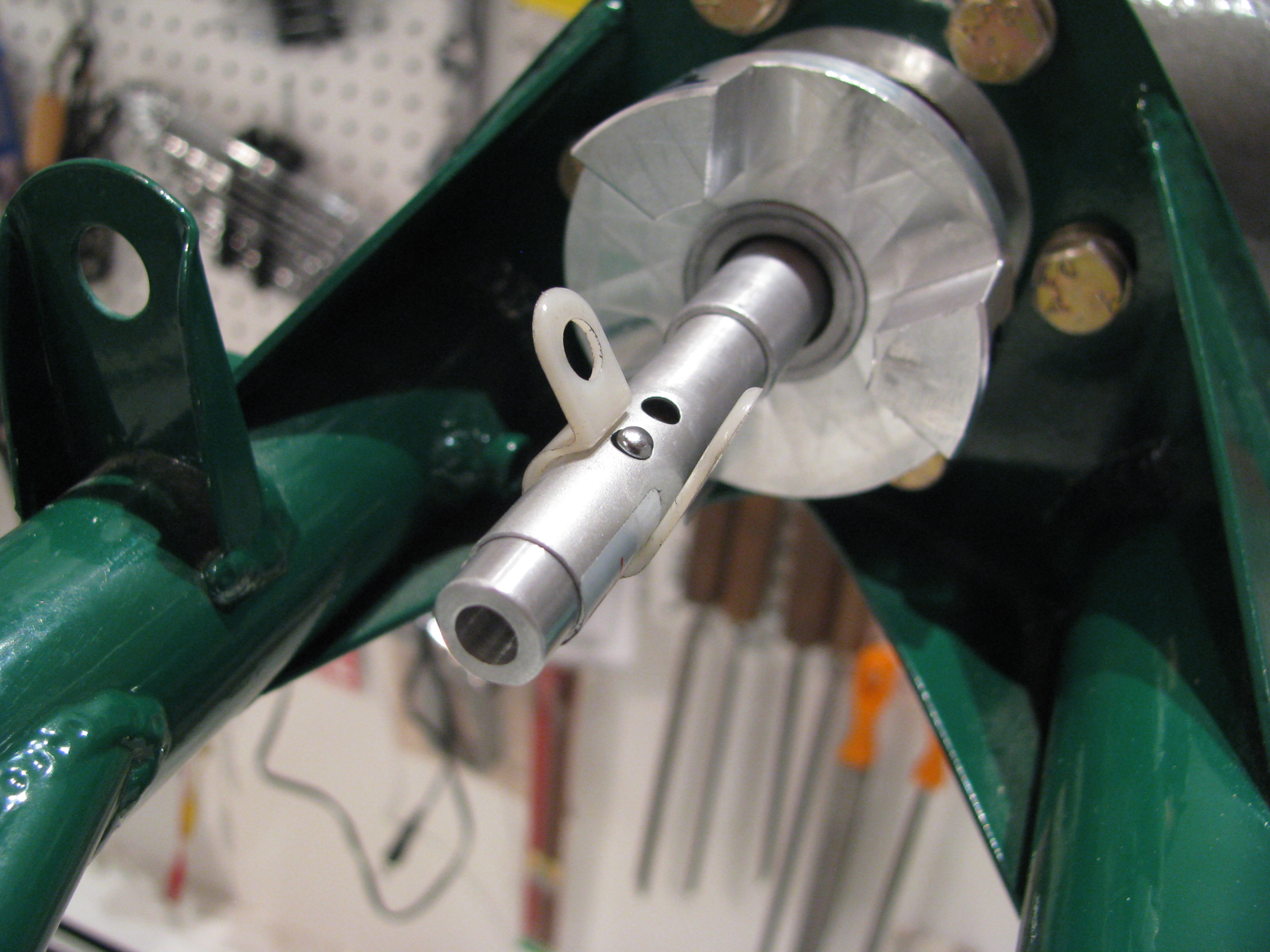
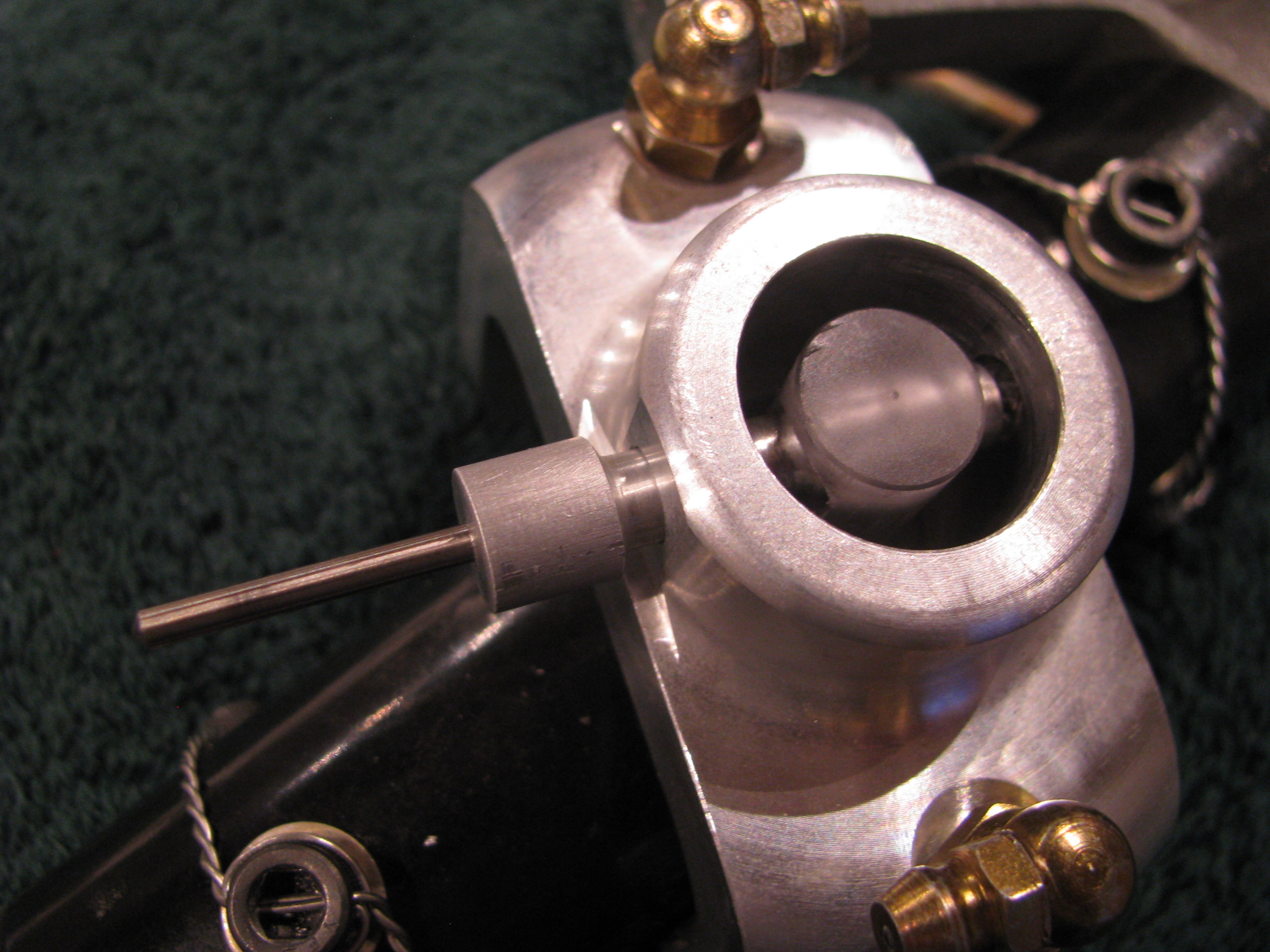
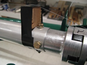
2/17/12 - I backed up a little. Even though I did BJ’s measurement procedure as detailed above, I realized that the two bearing blocks were only rough placed so the reference for measurements was not very exact to begin with. I fabricated a laser pointer alignment jig as others have done.
Get the smallest one you can find. Machine a spacer to sleeve it into the TR gearbox shaft. Realize that $2.99 laser pointers are not precision instruments. The beam is nowhere near coaxial, so as the shaft turns it circumscribes a circle at the far end. The shaft points to the center of that circle. It confirmed the CCW cant measured from the previous entry, but also showed a very slight downward point that I will have to shim out as well. That white plastic ring is a wire hanger just to hold the button down while measuring. I also machined a new front ring to hold the Laser diode more centered, but it didn’t help much. The beam is still canted off center. Leave a little slop in the sleeve so the pointer can be nudged to reduce the size of the circumscribed circle.
This is where it gets interesting only to Helicycle nerds. After using the laser to align the TR gearbox and adding 0.010 and 0.005 shims appropriately so the TR gearbox shaft is pointing as close as possible to the center of the output shaft on the main transmission I get the following:
1 - 0.031, 4 - 0.030 These are the top and bottom dogs. Delta=0.001”
2 - 0.029, 5 - 0.032 Top right and bottom left dogs. Delta=0.003”
3 - 0.028, 6 - 0.034 Bottom right and top left dogs. Delta=0.006”
So that’s a differential of 0.006” indicating an every so slight downward and CCW cant of the TR gearbox. This is much better than my initial attempt before fabricating my laser alignment tool and way tighter than the spec in the video. I should also note that I did the full string jig shaft alignment method prior to measuring
At the opposite end I measured the following clearances between the mating dogs at the main transmission end:
1 - 0.022, 4 - 0.044 These are the top and bottom dogs. Delta=0.022”
2 - 0.023, 5 - 0.043 Top left and bottom right dogs. Delta=0.020”
3 - 0.036, 6 - 0.032 Bottom left and top right dogs. Delta=0.004”
Not much can be done here. As expected this indicates that the main transmission is canted CCW as viewed from the top. This is expected as we built in some twist to balance out the expected torque. Also, the TR shaft is tilted slight up relative to the main xmission, so there’s not much that can be done there either.
I should note that nothing has been drilled yet, this is just placement and measuring to make sure everything fits and is spaced properly prior to drilling the shaft tubes to the bearings and dogs. Next up is to work out the appropriate bolt spacing and to figure out how I am going to drill the bolt holes perfectly.
Finally the Ticket!!!
02/11/12 21:50 Filed in: All
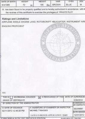
Finally and at long last! As of this afternoon the key words “ROTORCRAFT HELICOPTER” are now added to my ticket. I ended up spending far more time in training to get my helicopter license than my fixed wing. I logged about 65 hours in training to get here.
The exam and checkride process was very detailed. About 2 hours talking helicopters for the oral portion, and 1.4 in the air. Very thorough. We must have gone through every maneuver in the book. The most challenging was the surprise power cut on downwind. Had to do an auto “for real”. Decide where to go and execute. I elected to do a 180 auto back to the runway based on where I was - and it all worked out OK, though the added second of recognition when it is a “surprise” allows the rotor RPMs to drop a lot lower than when you’re doing them for practice. That was an eye opener. I caught it in time, and the 180 degree turn helped bring the RPMs back up quickly. It even surprised me just how automatic lowering the collective was. Once I got over the “Hey, you can’t do that...” reaction.
Much like the fixed wing license, I am quite conscious that simply holding the license does not make me an expert, but merely minimally competent and equipped with the tools to help prevent me from doing myself in while piloting one of these unlikely machines.
I will try to stay current, but will definitely be back for a bunch more training prior to attempting to pilot the Helicycle.
Tail Rotor Shaft Start
02/06/12 11:20 Filed in: All
Started on the tail rotor and drive shafts. First task is to mount the TR gearbox. Off and on about a dozen times with lots of little trimming with the a rat tail file to open up the mounting holes. Nice and snug with no play when tightened down. The angle between the main mast and the TR shaft is about 89.5 degrees. BJ says less than a couple of degrees is OK, so there is no need to bugger up the mounting holes by trying to achieve a perfect 90. Better to keep them tight and live with the very minor angular misalignment.
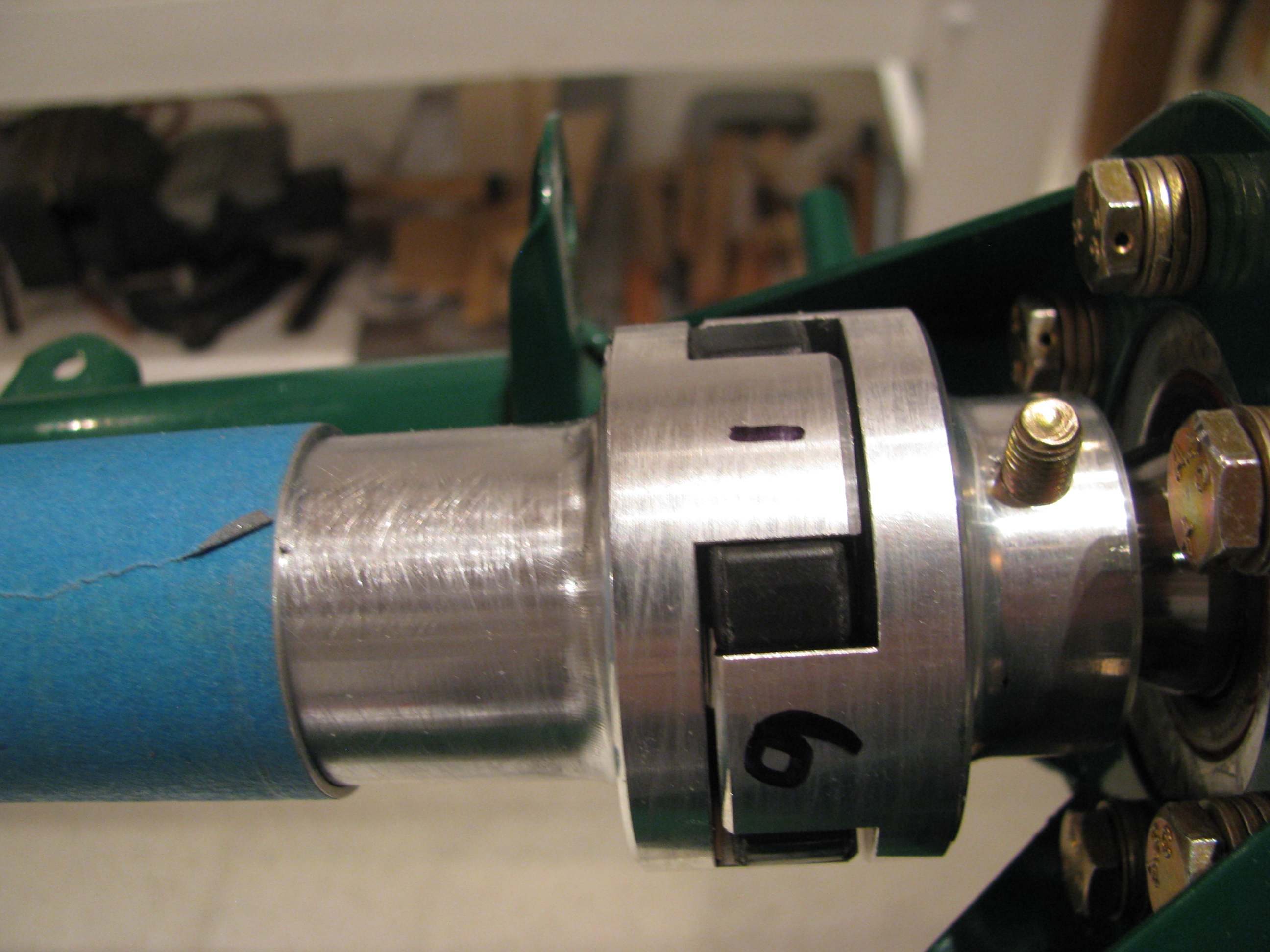
Shaft sections are cut and first order fitting completed. A lot of fiddling required to get the lengths right. Fit is very tight over the bearing inserts, so it takes some sanding/polishing and a daub of grease to get them to slide on. That will be mostly removed on final assembly. There is a definite sequence of assembly required. Start at the front since the bearing blocks all mount from the rear.
Small cuts and sanding, then retry. Very time consuming.
To get the TR gearbox aligned required a thick washer on the bottom and a thin in the middle, and none at the top on the outside of the frame between the gearbox and the frame. This is almost the opposite of what BJ required in the video. Like his example, almost no left/right differential was required, mostly up/down.
At the TR gearbox the distance between the dogs and the mate is measured. The goal is less than 0.020 differential side-side or up/down. I numbered the ears and measured the following:
1 - 0.030, 4 - 0.029 delta = 0.001
2 - 0.025, 5 - 0.035 delta = 0.010
3 - 0.024, 6 - 0.034 delta = 0.010
It is numbered this way because measurements 1 and 4 are on opposite sides, 2-5 are opposite, and 3-6 are opposite. The greatest difference is 0.011 between any two and there is definitely less than 0.020 difference, so I am satisfied (almost). I may try to add my thinnest shim stock to the 3 right side bolts to try to remove the slight CCW cant (viewed from top) and get it as close to perfect as possible. Now is the time as it’s unlikely I will revisit this until final assembly.
Shimming Hood Bearing
01/29/12 11:16 Filed in: All
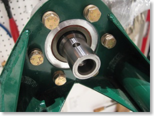
Done mounting the main transmission. The last task was to shim the hood bearing so that there is less than 5 mil clearance between the alignment ring and the bearing top surface. I rotated the check ring to account for imperfections in the check ring - 4 checks 90 degrees apart. In one orientation the 0.005 feeler slides in between for an arc of about 20degrees. Since I plan on alodyning these shims I will reexamine after that is done since that will thicken them up slightly.


Drilling Transmission
01/22/12 11:15 Filed in: All
OK. After procrastinating long enough and measuring and remeasuring, I finally drilled the transmission to the frame. Even with all my careful measuring and clamping, after I drilled and rebolted everything together snugly I went back and measured the offset. BJ wants the right side to have more pre-built offset by 1/4” measured at the first bearing block. When everything was final/final, I measured .350” more on the right. I was super careful. Something must have shifted ever so slightly during drilling. That extra tenth translates into about 5/100 of a degree. Hopefully this will not affect the final alignment too much.
The holes are all reamed and there is no detectable slop at all, which I think is probably more important.
I am happy with how the hood bearing block slides cleanly down to the hood with absolutely no touching of the hood metal. This means there’s no preload or stress on the mast imparted by the frame mounting.

The holes are all reamed and there is no detectable slop at all, which I think is probably more important.

I am happy with how the hood bearing block slides cleanly down to the hood with absolutely no touching of the hood metal. This means there’s no preload or stress on the mast imparted by the frame mounting.
Transmission Alignment
01/21/12 11:14 Filed in: All
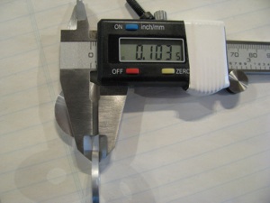
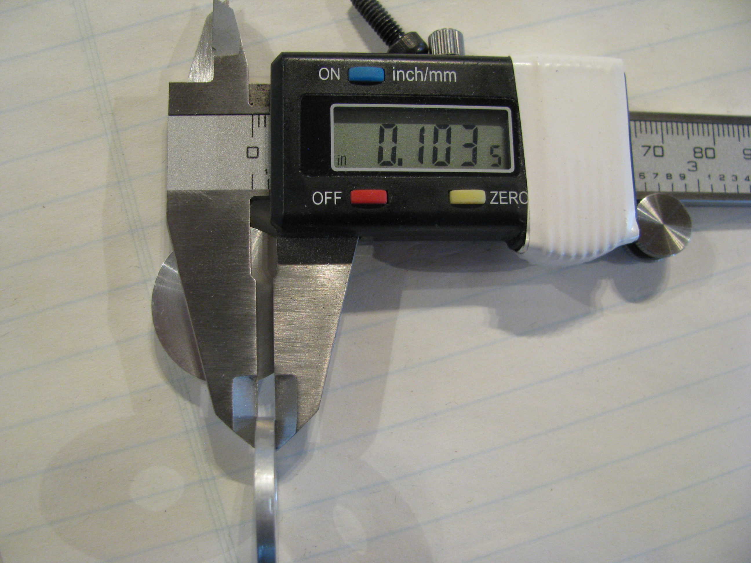
Fiddling with alignment of the main transmission. Fabricating spacers. Aligned everything. Measured gaps and now fabricating precision spacers. First was the left side. The gap between the mounting tab is 0.103 on the outside and tapers to 0.089 on the inside. The tab has a little tilt and the casting is not exactly level-flat. Roughed a blank on the lathe. Fashioned a holder, then faced down to 0.103 and drilled out the center hole to 5/16”. Finally hand-sanded the tilt from 0.103 outside to 0.090 inside and fit to ship.


Initial Transmission Fit
01/14/12 00:09 Filed in: All
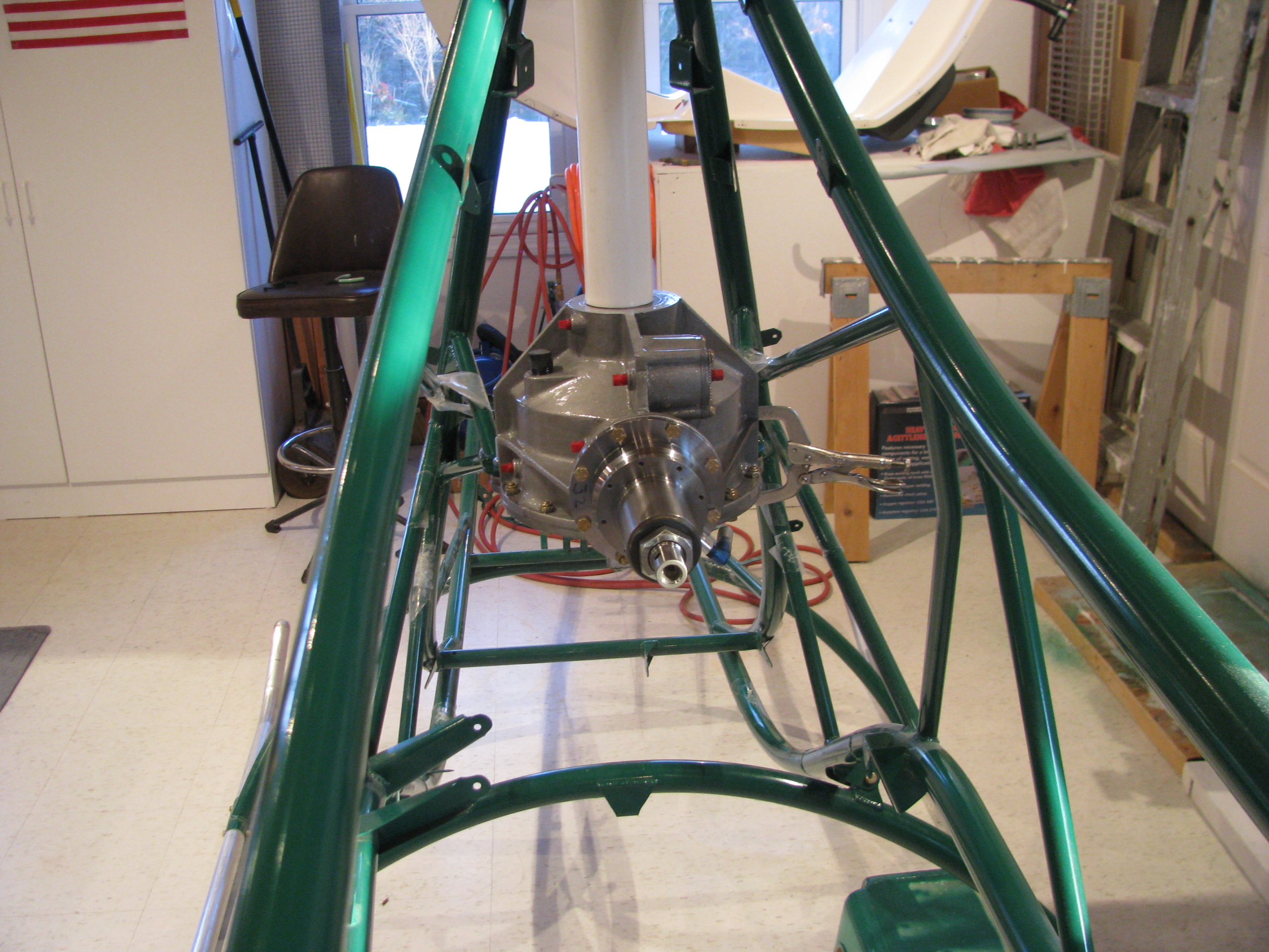
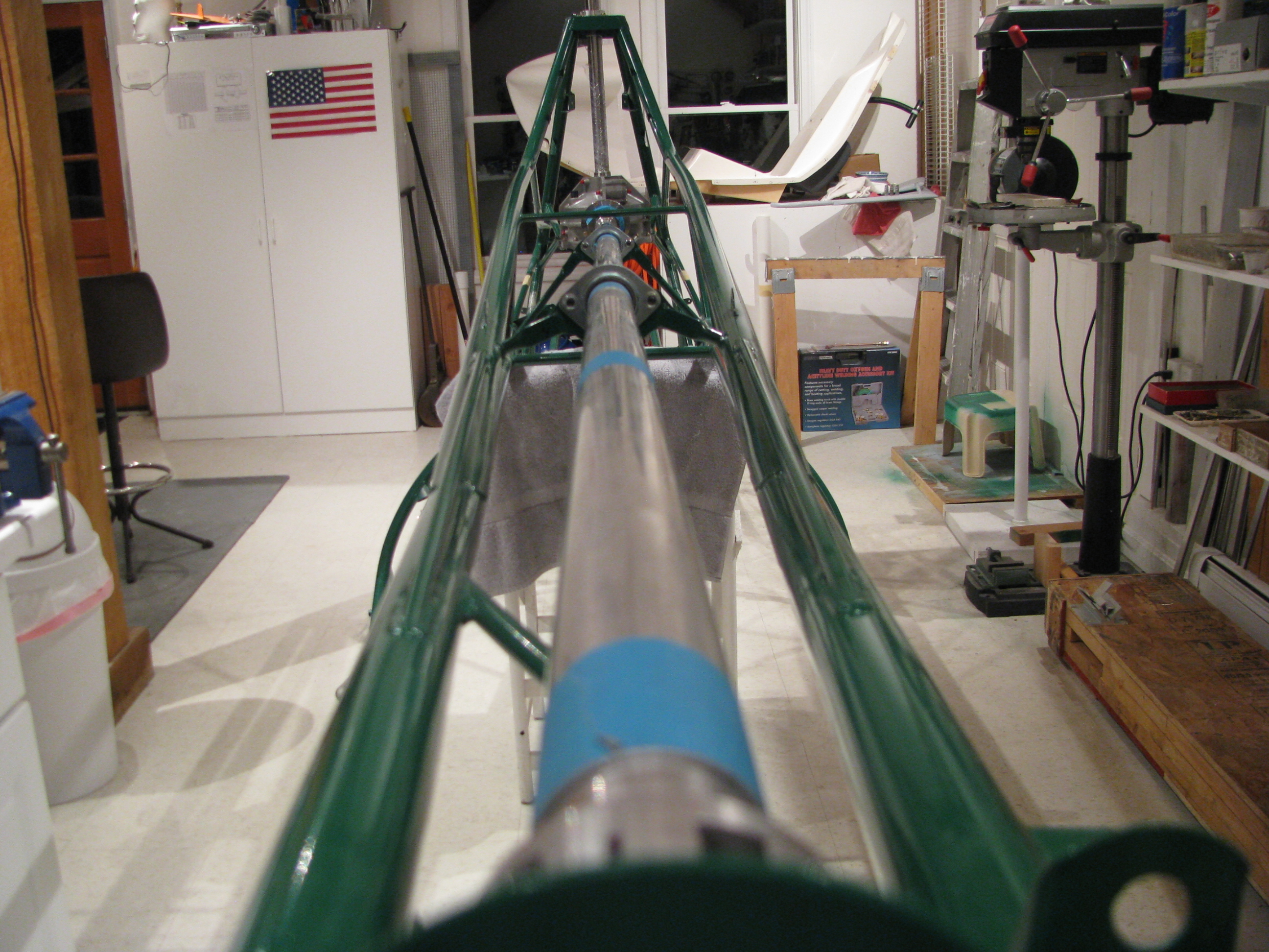
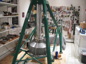
Hooray! Transmission preliminarily in place. That’s a piece of 2” PVC pipe, which fits perfectly to protect the shaft while sliding into position. This is definitely a 2 person operation.
Once in place I clamped a piece of wood underneath the transmission so I can lower it a few inches to clear the tabs when needed.
Ran the alignment string and rough set the pre-load offset angle (very precise twist/measure/clamp/repeat).
The undrilled side tab was not exactly parallel, so it had to be bent down about 0.75degree.
When the pre-drilled bolt was snugged, the first to bottom was the undrilled side. It also looks like the inner side of the tab touches first. I could either make an angled shim or perhaps take a touch of aluminum off the casting. I don’t want to stress the tab welds by trying to impart a twist in the steel tab.
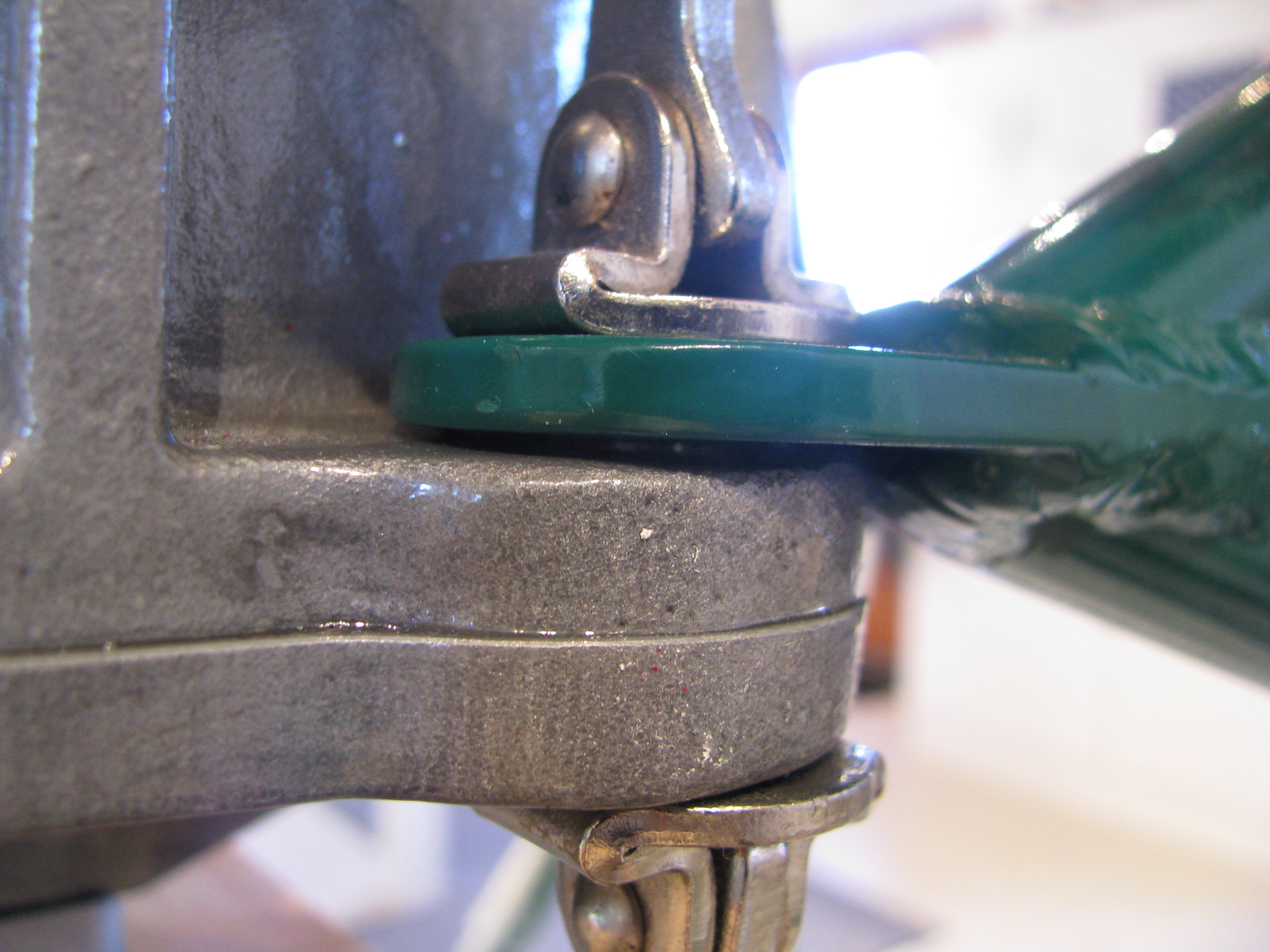
With the undrilled (right) side bottomed there’s a 63 mil gap between the left-side side tab and the casting. The photo also makes it look like they are not parallel. I’ll double check to make sure this is not a trick of the camera lens.

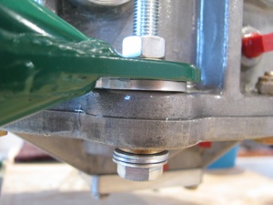
With everything jigged and clamped you can see the uneven gap at the hood bearing. It’s maybe 0.040” at its largest which is exactly on the right side of the ship. I think much of this is probably due to the built-in slight leftward tilt of the mast. I’ll work the main mounts before worrying to much about this.
I can judge the left/right tilt of the main mounts by making sure this bearing housing slides up and down easily when the main mounts are in position and clamped. I guess the fore-aft tilt of the main transmission is locked in place by the lift strut. I’ll have to play with that a bit. I will probably diddle around with this for a few hours to make sure every angle and clearance is understood and addressed before making permanent changes (ie: drilling that undrilled tab and the lift strut mount). Mistakes here would be difficult to fix and very expensive.
Transmission Prep
01/01/12 00:07 Filed in: All
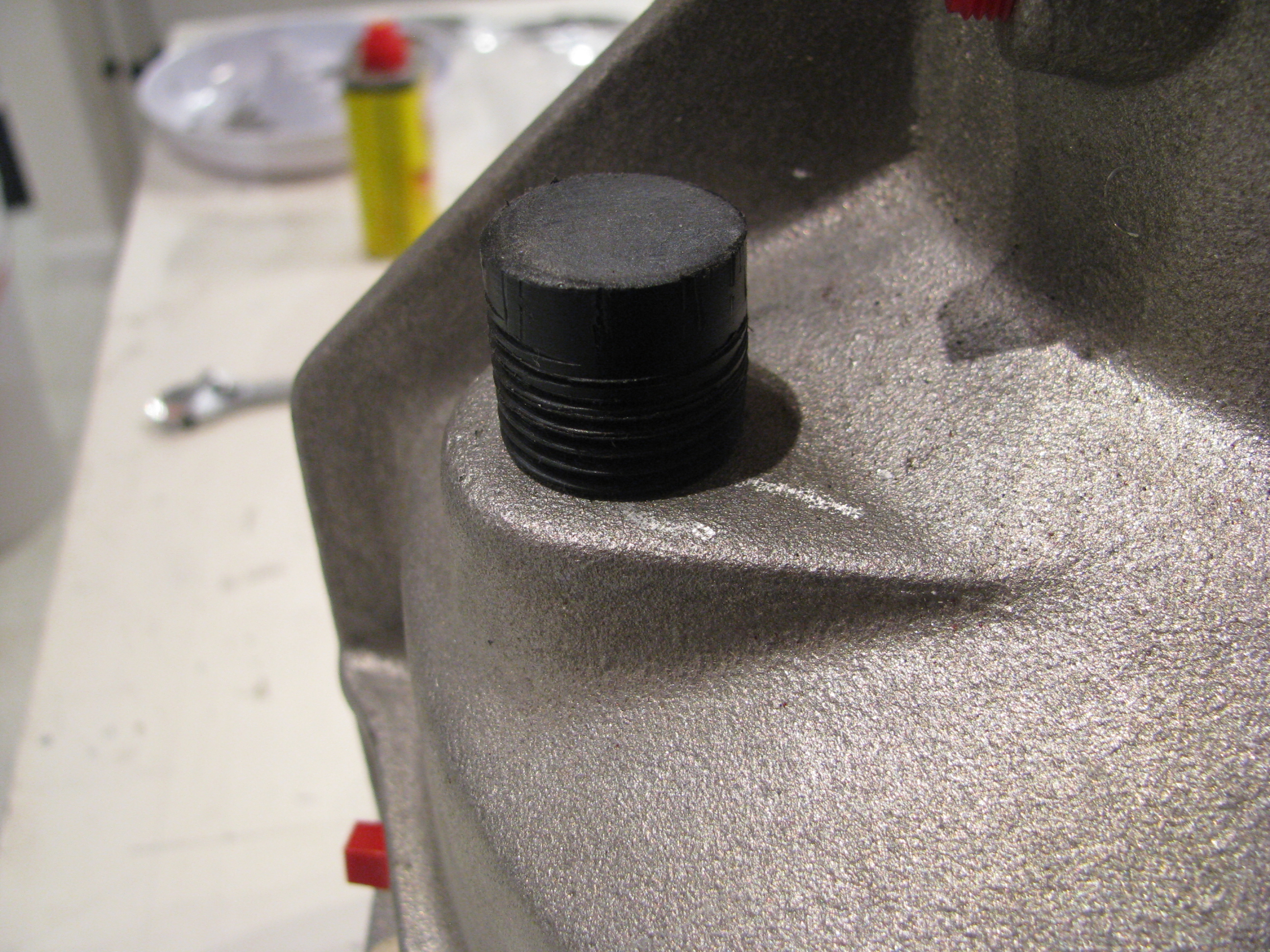
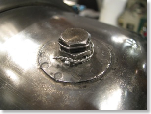
Here is why my progress slows to a crawl sometimes. BJ says to make a little wooden plug to cover the transmission fill during painting. Well, instead of wood, I turned this this little plastic block down on the lathe and then threaded it to 1/2” NPT pipe thread. I messed up the threads and had to make a new one. Of course cutting plastic on the lathe is very messy, so I had to clean up the shop afterwards. All told about an hour and a half to make a stupid little plug.
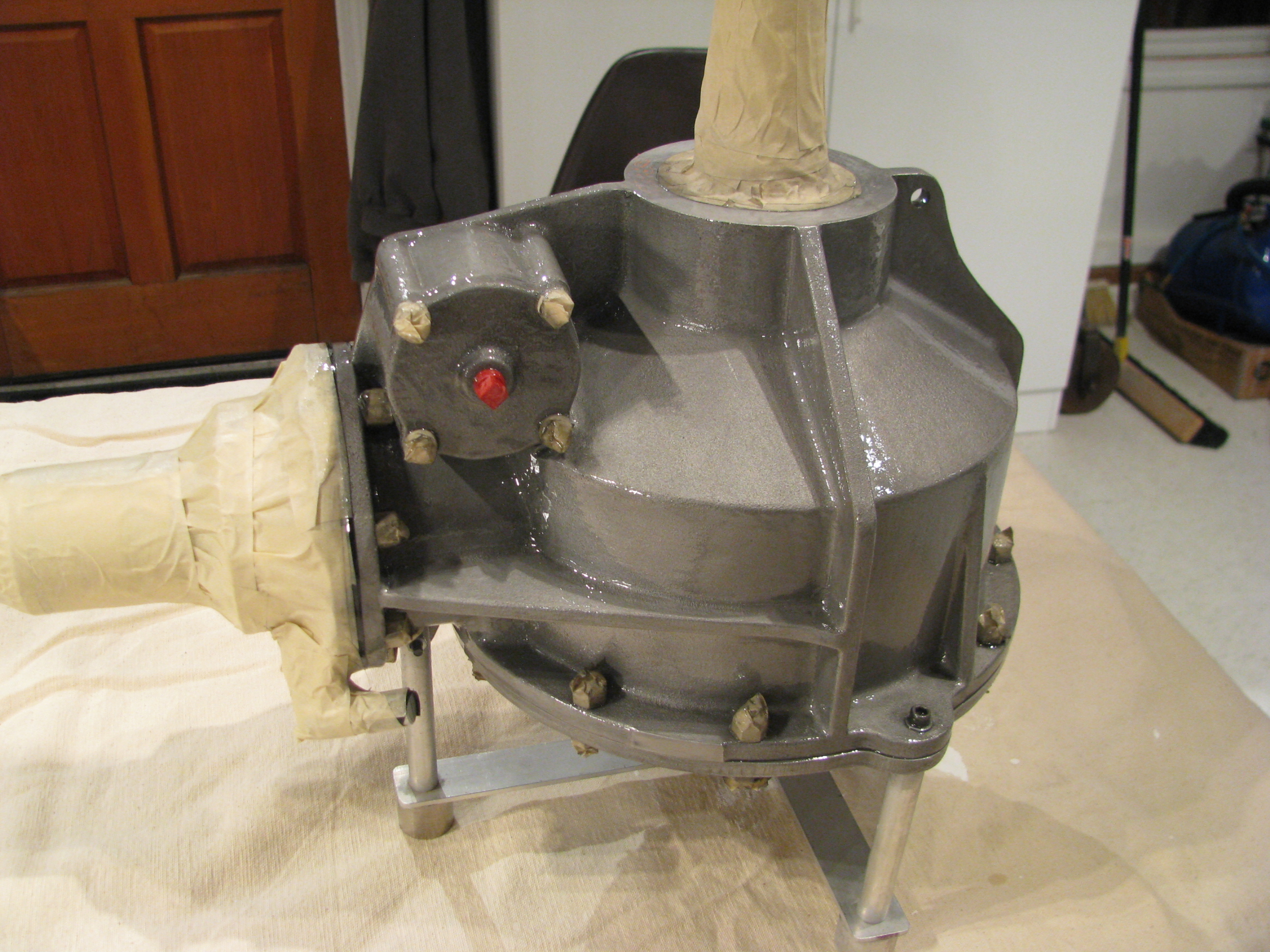
Sandblasted with 80grit followed by 220, then wirebrushed with stainless steel and then a brass brush. It looked fantastic before the painting, but of course that wouldn’t have lasted. Two coats of POR-15 clear. One light to “seal” the casting, then one medium-heavy to level it out all with a brush. It looks candy-coated now.
It took almost a full week of curing before it stopped feeling tacky.