
2010
Moving & Restarting
09/28/10 16:49 Filed in: All
 It had to happen that as soon as I acquired the Helicycle and bought a lathe we ended up selling the old house. After 2 years on the market and a bunch of jerking around we finally accepted an offer (for a fraction of our original asking price, of course).
 One of the motivators in settling for a lower price is that we had found a new place on top of a hill, 360 views, and a large outbuilding which has turned into the new airplane factory.
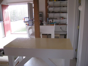
I started by gutting the outbuilding, tearing out the walls and retiling the floors. All the wiring had to be redone, drywalling, and finishing. White white white. It looks like an operating theater now.
I built worktables, installed shelving, and redid the lighting. Between the move, and the refitting of the shop, I did not get anything done on the aircraft until well into fall.
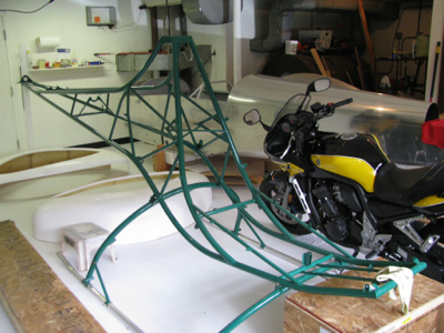
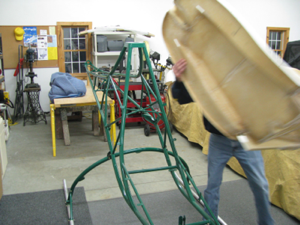
It looked huge right up until the airplane and helicopter fuselage and frame were brought in. Now it’s quite snug.
My personal vow is that we will NOT move again until the airplane and helicopter are finished. What a PITA to move that stuff.
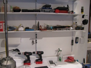
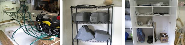
Lots of shelves and countertop space.
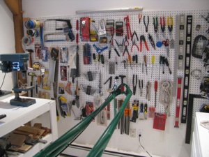
New pegboards gave a chance to reorganize the tools. It’s nice to have them all neat and logical again.
I was pretty lost for a couple of months during the move with everything in boxes. If I needed a wire stripper it was an hour-long treasure hunt through boxes.
Much, much happier now knowing where everything is.
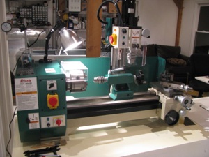
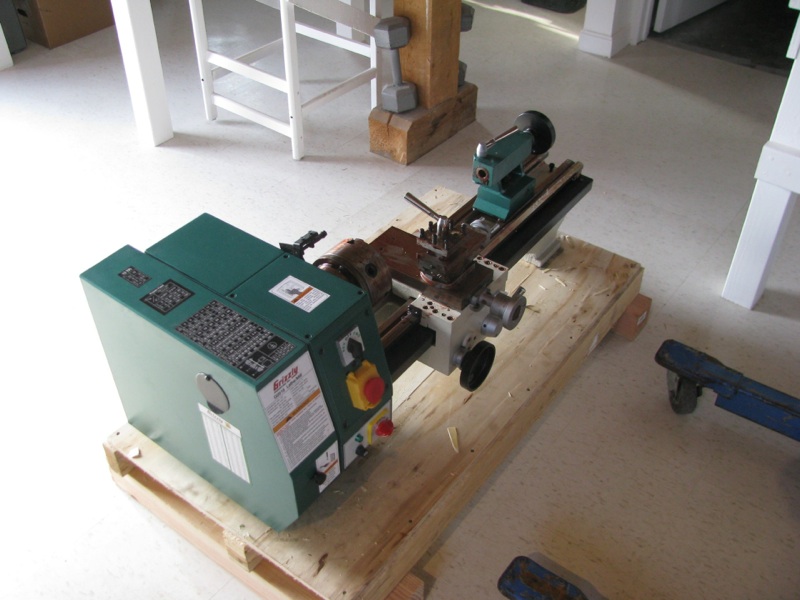
Just prior to selling the house (and the REAL trigger for getting a good offer), was my taking receipt of a Grizzly G0516 Mill/Lathe. This is a couple of steps up from a little mini lathe.
Yes, yes, I’ve read all the reviews saying a 3-in-1 is not as good as separate machines, but I have limited space, and don’t see myself using it every day.
I have played around and made some small items so far. Fun. Looks like it will more than meet my limited needs.
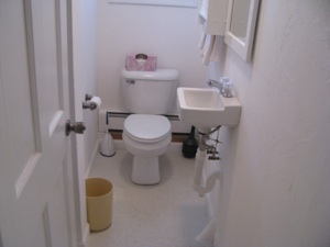
One of the more luxurious aspects of the new shop is having a bathroom and shower. A small electric water heater caps it.
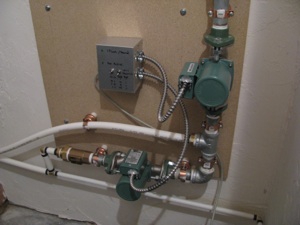
Unfortunately the water run to the shop was buried less than 12 inches from the surface underground. The biggest single project I undertook was to dig up the old water run, and dig a new trench (by hand) 36-48 inches deep. 137 feet long. There were two spots where ledge prevented a deep lay. The pipes are about 8 inches deep at those points.
I ran a conduit with 2 x1”insulated PEX pipes. In the house there is a loop manifold.
In the shop I put two circulator pumps. One just loops water through the feed and return. The second circulator loops the feed through the hot water heater and back out the return.
I can program the timer to loop hot water 1 minute out of 10 or 1 minute out of 20, depending on how cold it is out.
If I get super motivated someday I will add a thermocouple to the return and optimize so I am not
paying as much to heat the ground.
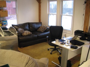
One section of the shop is set up as an office/lounge with a desk, couch, comfy chair, laptop, internet and a TV.
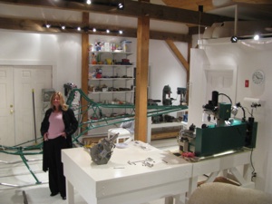
Comfy shop, beautiful wife. Should be a good place to work and play.
Flox Pads
05/09/10 16:37 Filed in: All
I laid up a strip of fiberglass on the right hand side between the tabs. The pan currently rests on the tab welds, and I don't want to grind those or the flat part of the pan, so I will build up the area between the tabs slightly. Two strips of cloth was not enough, so I will probably build a little dam and pour a thin strip of flox (resin and cotton fibers) between the tab locations and sand it down until the pan rests on it.
I did this little section first to get reacquainted with fiberglass. It's been a while. Warm the resin! My can was maybe 65 degrees when I poured it and it glooped out like toothpaste. I had to heat the cup in a pan of warm water until it flowed like honey before starting. I remember that now and have re-set-up my box with a lightbulb to keep the resin warm on fiberglass days. Unlike most RV builders I actually like working with fiberglass. It's kinda magic to take chemicals and floppy cloth and build something remarkably strong out of it.
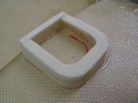
I made little U-shaped dams out of urethane foam to contain the flox "pads" for the seatpan mounting tabs. The foam was tacked down with 5-minute epoxy, then the flox was mixed and poured into the cavity. Flox is much thicker than resin, but still thin enough to flow, so you have to either pour it flat or contain it.
On the left side curve (second tab down from the top, the distance is quite large. Instead of bending the tab a ton, which will draw the hole closer to the curve of the seatback, I will just build this one up taller and leave the tab only slightly tweaked to be flat with it.
Flox poured. In all cases I built the pads to be taller than needed so I can then sand them down. The foam will then get sanded to a nice radius and a layer of thin cloth laid up over the top of the whole thing.
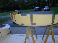
I cut the scribed slots in the fuselage halves. Overall the fiberglass looked sound, and there are just a couple of locations on the edges where the gelcoat got thick and there is a little separation between fiberglass layers. Those will get sanded out and a new strip of cloth or two added since they're right on the joggle lip mating surface and need to be strong. Gelcoat is non-structural. The interior is quite sloppy. There are a lot of little hairs and some places where resin pooled up. I will sand those down and probably be able to take down enough to compensate for the weight of my flox pads. Net sum zero on weight gain for my mods.
I may be critical of certain things on this kit that are less than perfect, but overall I am impressed by what you get for the money here. I have no idea how Eagle can do this for the price of the kit.
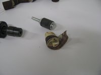
The sanding drums for the die grinder are quite remarkable. They work great, right up until you catch the end on a lip or edge, then they explode, sounding like a gunshot going off and just disappear at high speed across the room. I've used this thing a lot and have never done that before, then I had it happen twice in ten minutes. Guess that means I'm getting sloppy and it's time to stop for the day.
Eye, ear, and dust protection are a must.
More Pan Fitting
04/28/10 16:25 Filed in: All
I pulled the wood doubler out from between the collective pocket and the edge of the seat pan. I don't really know what it was supposed to do, but judging by how easily I was able to tear it out, not much. It was clearly glassed in as a secondary operation and an afterthought. If there is clearance after the seatpan is fit, I may glass in a layer just for peace of mind.
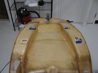
 You can see that the pan drops much further down on the left side now. So much so that instead of being canted to the right on the frame, it is now canted to the left. However, that single modification of removing that wooden piece allowed the seat pan to "nest-in" much better, and the clearance between the pan and the mounting tabs is now less than 1/4 inch all around. With my floxed pads and very, very minor bending, this will be a clean fit (my prediction).
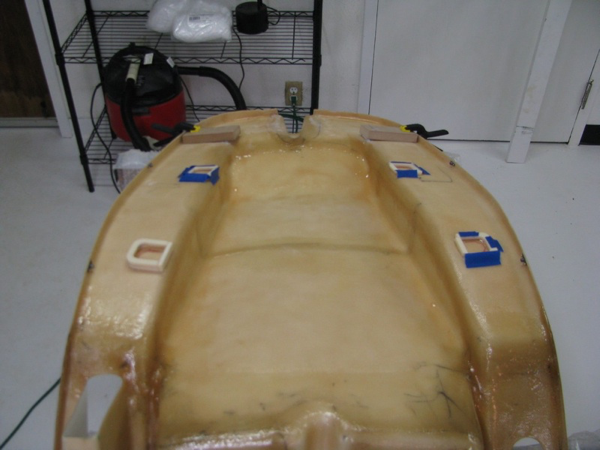
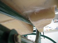
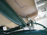
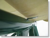
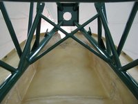 This view is looking up from the bottom at the back of the seat pan. You can see now that the seat is offset to the left. I am discovering the limitations of the "video" approach, instead of a manual and blueprints. I would very much like to know the exact offset of the control rod clearance tunnel at the top of the seat pan relative to the hood bracket at the top of the frame. You really have to watch BJ closely. As far as I can tell, he only mentions in one brief sentence, much later on, that the hump is intended to be aligned with the hole at the top of the frame, and the seat pan edges are centered relative to the frame tubes.
Of course with some prints and a manual this would all be immediately evident. Instead you have to watch the same video over and over (drives my daughter nuts) to try to glean this.
Perhaps I just got spoiled with the Van's RV8A kit, which has great documentation by comparison. Now don't get me wrong, I am immensely impressed with the Helicycle kit so far. For the money spent, the frame, fiberglass, materials, and especially the machined parts appear to be of very high quality. The budget was spent on machining parts and tooling, and not on documentation.
The source of the misalignment are the vertical tabs next to the collective pocket. Looks like those have to be bent inward a hair.
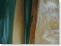
One thing I do not like about the fiberglass is the appearance of the bottom surface. The whitish areas almost appear as if they weren't wetted out fully. When I get my epoxy I will probably brush on a thin coat to "seal" them. It doesn't look to be a structural issue, but certainly a cosmetic one that bothers me.
I looked ahead in the videos to the next step, which is the instrument pod mounting. I did not get the 12 inch long 3/8" drill bit when I picked up the kit, so I'll probably have to order one. I must admit that the "jiggle and elongate the holes" approach does not excite me. I'm pretty sure there must be some sort of clamping arrangement that can be constructed to more precisely achieve the same effect. I don't like the idea of elongating the holes, then tightening the bolts to hold it all in place. Once again, I will consult Tim Drnec's and Juan R's sites to see what they did. Those two guys really set a high bar when it comes to fastidiousness and quality workmanship. While I want a straight, true, clean, and reliable ship, I doubt that I will be able to meet their standards of excellence.
Of course with some prints and a manual this would all be immediately evident. Instead you have to watch the same video over and over (drives my daughter nuts) to try to glean this.
Perhaps I just got spoiled with the Van's RV8A kit, which has great documentation by comparison. Now don't get me wrong, I am immensely impressed with the Helicycle kit so far. For the money spent, the frame, fiberglass, materials, and especially the machined parts appear to be of very high quality. The budget was spent on machining parts and tooling, and not on documentation.
The source of the misalignment are the vertical tabs next to the collective pocket. Looks like those have to be bent inward a hair.
One thing I do not like about the fiberglass is the appearance of the bottom surface. The whitish areas almost appear as if they weren't wetted out fully. When I get my epoxy I will probably brush on a thin coat to "seal" them. It doesn't look to be a structural issue, but certainly a cosmetic one that bothers me.
I looked ahead in the videos to the next step, which is the instrument pod mounting. I did not get the 12 inch long 3/8" drill bit when I picked up the kit, so I'll probably have to order one. I must admit that the "jiggle and elongate the holes" approach does not excite me. I'm pretty sure there must be some sort of clamping arrangement that can be constructed to more precisely achieve the same effect. I don't like the idea of elongating the holes, then tightening the bolts to hold it all in place. Once again, I will consult Tim Drnec's and Juan R's sites to see what they did. Those two guys really set a high bar when it comes to fastidiousness and quality workmanship. While I want a straight, true, clean, and reliable ship, I doubt that I will be able to meet their standards of excellence.
Rotor Head Arrives
04/27/10 15:56 Filed in: All
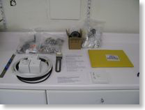
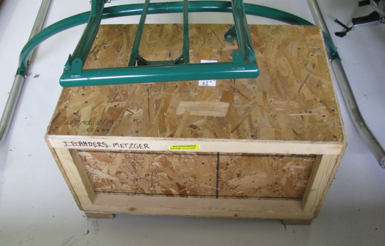 Unpack the rotor head crate. As I stated earlier, since the kit was purchased from another builder, most of the elements have been delivered or are on their way. The rotor blades and rotor head shipments arrived last week. The only item left is the turbine.
 Everything was in great condition. EXCEPT for a slit-like gash in the rotor head crate that I somehow missed when the delivery truck was here. I opened the rotor BLADE crate to inspect it since I figured that was the one subject to the most possible shipping damage being larger.
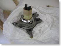
WRONG. It was perfect. The smaller box is the one with the gash. It looks like a forklift tine, or something, was sliced into the crate. There is a tiny nick on the rotor head that I will have to dress, but hopefully it is OK. That piece is absolutely gorgeously machined. My camera had trouble focusing on the nick since the piece is so shiny.
Pan Fitting
04/24/10 21:35 Filed in: All
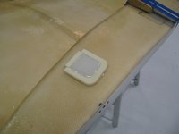
Fitting seat pan. Cleaned up holes and edges. Mounted nutplates (with flush rivets, instead of the pop rivets), and started trying to fit the pan to the frame. The fit is tricky. A lot more material than I would have thought had to be removed from the outsides of the front of the footwells. Lots of small trimming, then refitting of the pan.
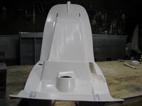
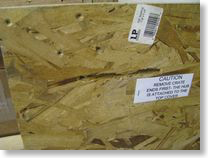
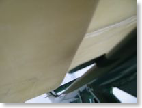
As can be seen below, a fair amount of material has to come off both sides of the front of the footwells to fit down between the two front frame tubes. The fiberglass is at least doubled up here around the bends, so hopefully the strength is not compromised too much. We shall see as this will probably be a high stress area in getting in and out of the ship.
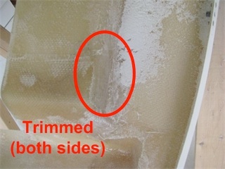
As can be seen below, a fair amount of material has to come off both sides of the front of the footwells to fit down between the two front frame tubes. The fiberglass is at least doubled up here around the bends, so hopefully the strength is not compromised too much. We shall see as this will probably be a high stress area in getting in and out of the ship.
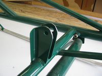
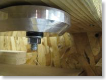
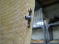
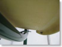
Shown here is the grinding I had to do on the control bracket to clear the seat pan as specified in the video. Still seems to be plenty of meat between the hole and the ground edge. There's about 1/16 of an inch clearance between it and the seat pan. I DO plan on repainting the frame after all the preliminaries are done just prior to final assembly. Green - what was he thinking?
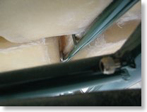
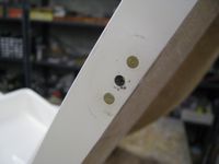
Here are the control tube mount tab locations when the front of the pan is flush against the mounting tabs. Pretty tight. I am going to shave a little off the inside of the round to fit the front plane of the pan down a hair lower.
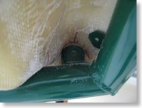
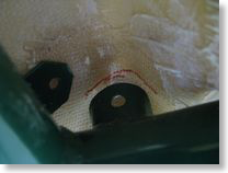
 Aft of the front two holes, the fit is not good. There is a large gap between the floor pan and the seat back. I am not sure I want to, or even could, bend the tabs enough to close the gap. Also, the seat pan is canted to the right. The right cant seems to be partially due to the frame first hitting the wooden reinforcing rod that is laminated alongside the collective pocket. I noticed on Tim Drnec's site that he just removed this piece, and I may do so too. It is kind of sloppily glassed in there. Tim glassed in anchor nuts to the rear of the seat back for a nice flush, no penetration, mount of the pan. Though I doubt I will go to that extreme, I do think I will build up the areas immediately underneath the mounting tabs with flox and resin to bulk up the mounting points. Though it's more work, I think it will beef up the fiberglass under the mounting points, which seemed a little weak with just a hole through that thin layer of fiberglass.
 I placed my first order to Aircraft Spruce for this project to get some fresh epoxy and flox for this procedure. Prior to executing this mod I also need to better jig the seat pan to the frame, especially in the rear before drilling any holes. There is quite a bit of side-side flex on the pan and I want to get it leveled and centered perfectly since the cabin mounts to the pan and presumably any errors will be magnified from that point onward. Perhaps I am seeming overly anal about this, but I want to be as precise as possible since this is a sophisticated and complex mechanical beast. In airplane construction there appears to be a little more wiggle room. Not so with helicopters. Precision matters.
As can be seen below, a fair amount of material has to come off both sides of the front of the footwells to fit down between the two front frame tubes. The fiberglass is at least doubled up here around the bends, so hopefully the strength is not compromised too much. We shall see as this will probably be a high stress area in getting in and out of the ship.
As can be seen below, a fair amount of material has to come off both sides of the front of the footwells to fit down between the two front frame tubes. The fiberglass is at least doubled up here around the bends, so hopefully the strength is not compromised too much. We shall see as this will probably be a high stress area in getting in and out of the ship.
Shown here is the grinding I had to do on the control bracket to clear the seat pan as specified in the video. Still seems to be plenty of meat between the hole and the ground edge. There's about 1/16 of an inch clearance between it and the seat pan. I DO plan on repainting the frame after all the preliminaries are done just prior to final assembly. Green - what was he thinking?
Here are the control tube mount tab locations when the front of the pan is flush against the mounting tabs. Pretty tight. I am going to shave a little off the inside of the round to fit the front plane of the pan down a hair lower.
Project Start
04/23/10 20:41 Filed in: All
Busy month. I finished refurbishing the garage, which is quite full at this point with the RV8A still in there, and all the fittings for the new project. I painted every surface white, and discovered something really cool. Periodically Lowe's has some killer deals on pre-fabricated bathroom cabinets. A couple of sections of those with a pre-fab countertop makes a nice workbench/storage cabinet. I am sure it is not precisely, perfectly flat, but pretty darned close. I will shim and do all critical tolerance work on my flush surface in the downstairs shop. The project is all here. I received the rotor blades from Eagle. The only thing left from them is the turbine itself, which I have no immediate need for anyway, so delivery, though promised "soon" is not super critical to me at this time.
Harbor Freight is my friend. I picked up a bunch of odds & ends I didn't already have; a 4" die grinder, more clamps, a 1" belt sander, blades, etc...
Real Project Work!! I first started by checking over all the Group 1 work done by the previous kit owner. He got as far as mounting the frame on the skids, then starting to clean up the seat pan. The gear mounting looks acceptable. His holes are square and I should just need to replace the hardware with known good and properly sized items at final assembly. Though his work seems acceptable, his color choices were not. Green?!? That'll change for sure. The seat cushions are also a hideous purple/pink combo which will probably end up getting replaced at some point.