
Electrical
Hap Miller Bits
11/11/13 21:45 Filed in: All
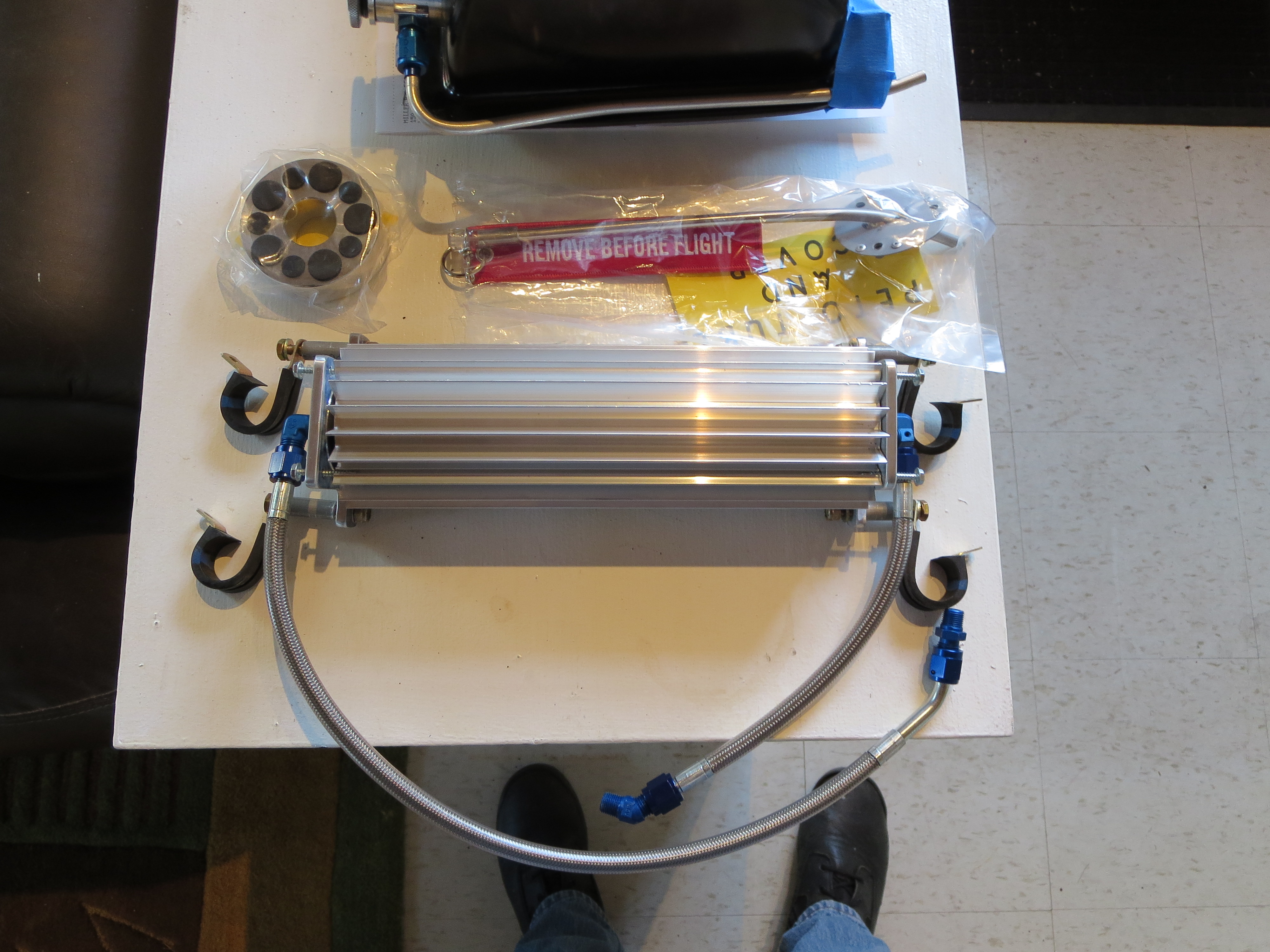
I ordered a bunch of bits and pieces from Hap Miller. Earlier I ordered and received his machined lift strut and it was of very good quality, so I wanted to see what else he has. Turs out a lot.
Here is the transmission oil cooler, clutch disk, and welded pitot tube. Nice!
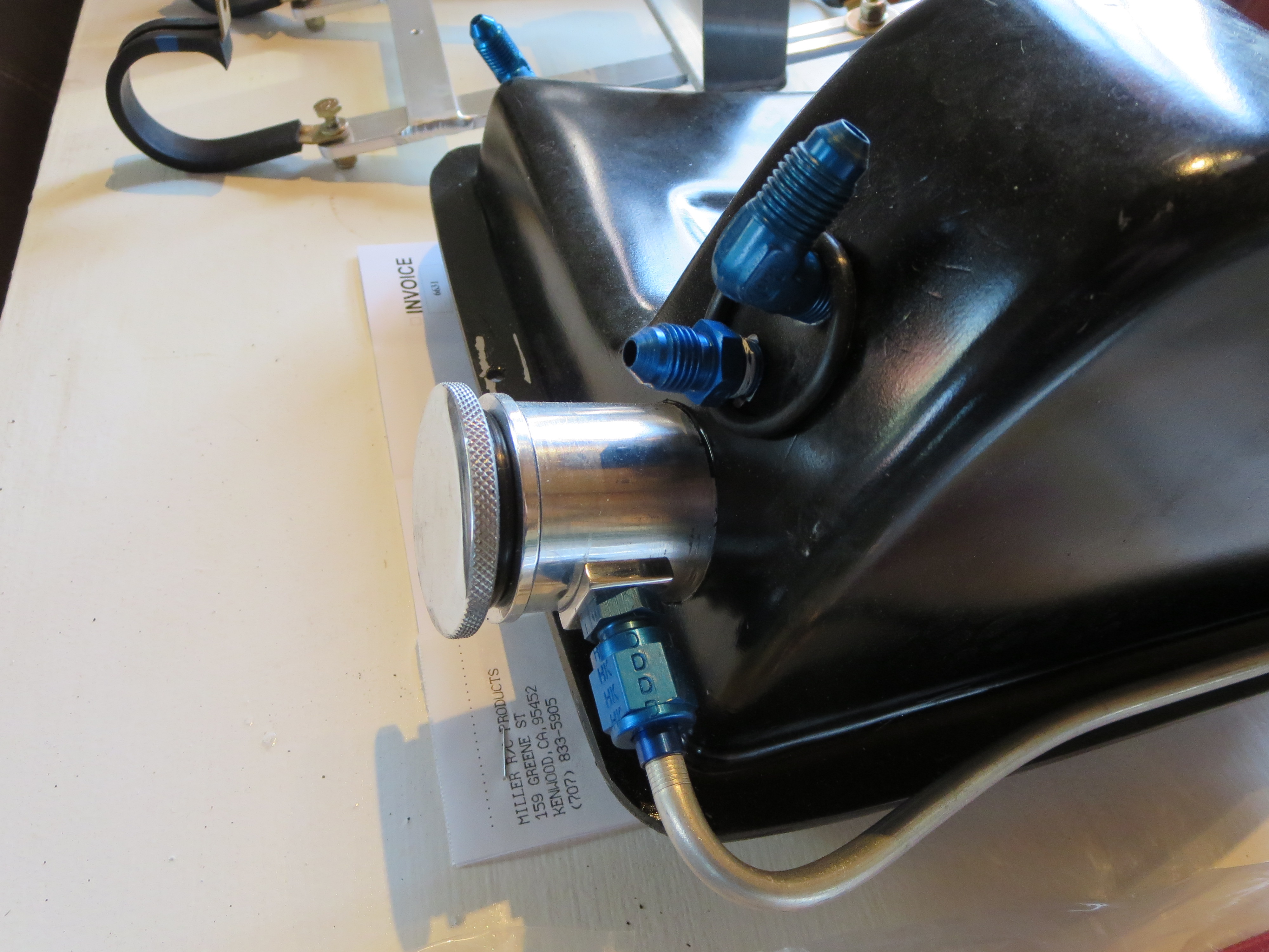
Hap claims that the "T" on the oil return to the tank actually impeded the return oil flow, so he recommends second fitting to return the oil independently and will add one to your tank. He also has a nice machined cap with integral dipstick.
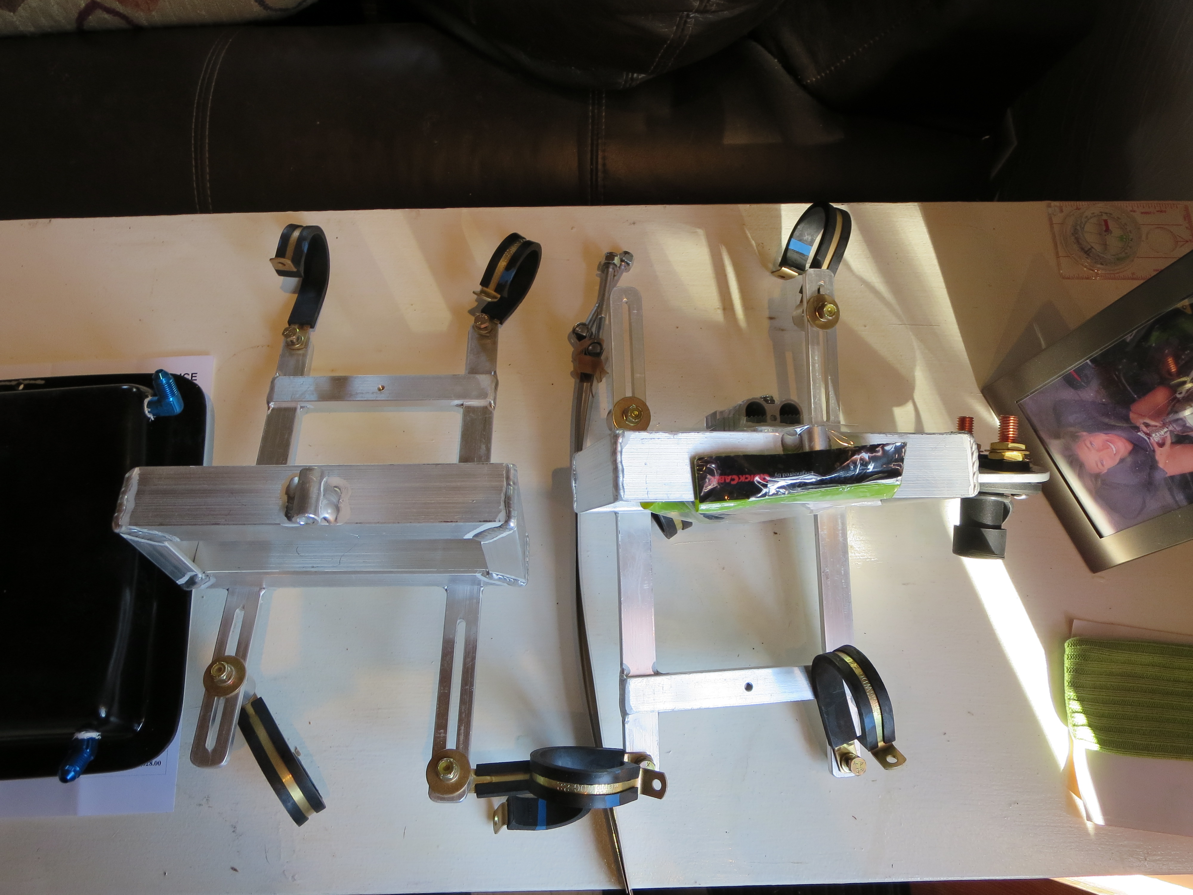
Lastly are the battery boxes. These mount just behind the transmission and accommodate a pair of Odyssey PC680 batteries. Nice aluminum welding work. It will be a shame to paint them and cover up those nice beads.
Ground Plane Paint
10/29/13 17:46 Filed in: All
For the structural parts I bought some enamel paint that matched the frame powder coating. This is the ground plane for the comm antenna.
Ground Plane Mounting
08/20/12 17:09 Filed in: All
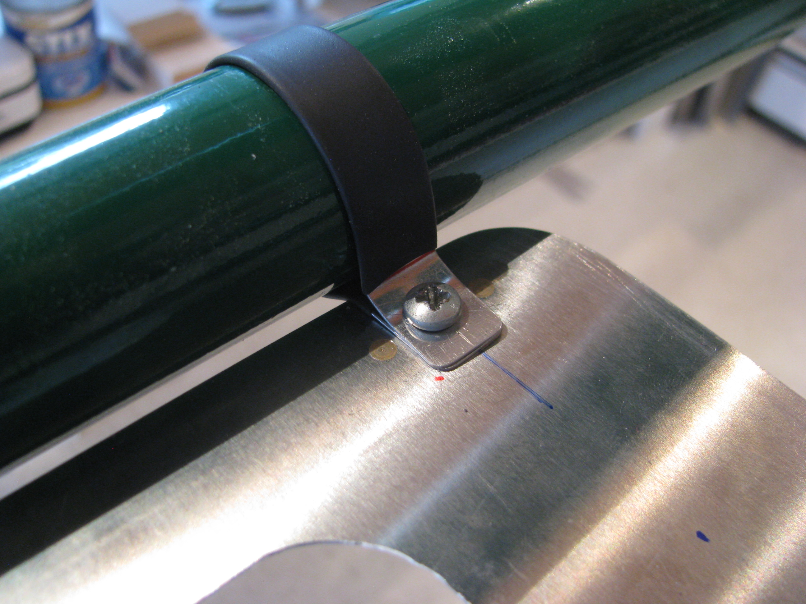
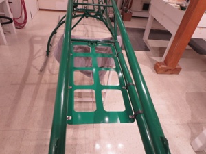
Completed the ground plane. I couldn’t see using Adel Clamps to secure it. Overkill. Instead I used little strips of 0.025 covered in shrink tube screwed through the ground plane to nutplates riveted to the bottom of the ground plane. Nice and tight, and it weighs next to nothing.
Ground Plane
07/24/12 16:39 Filed in: All
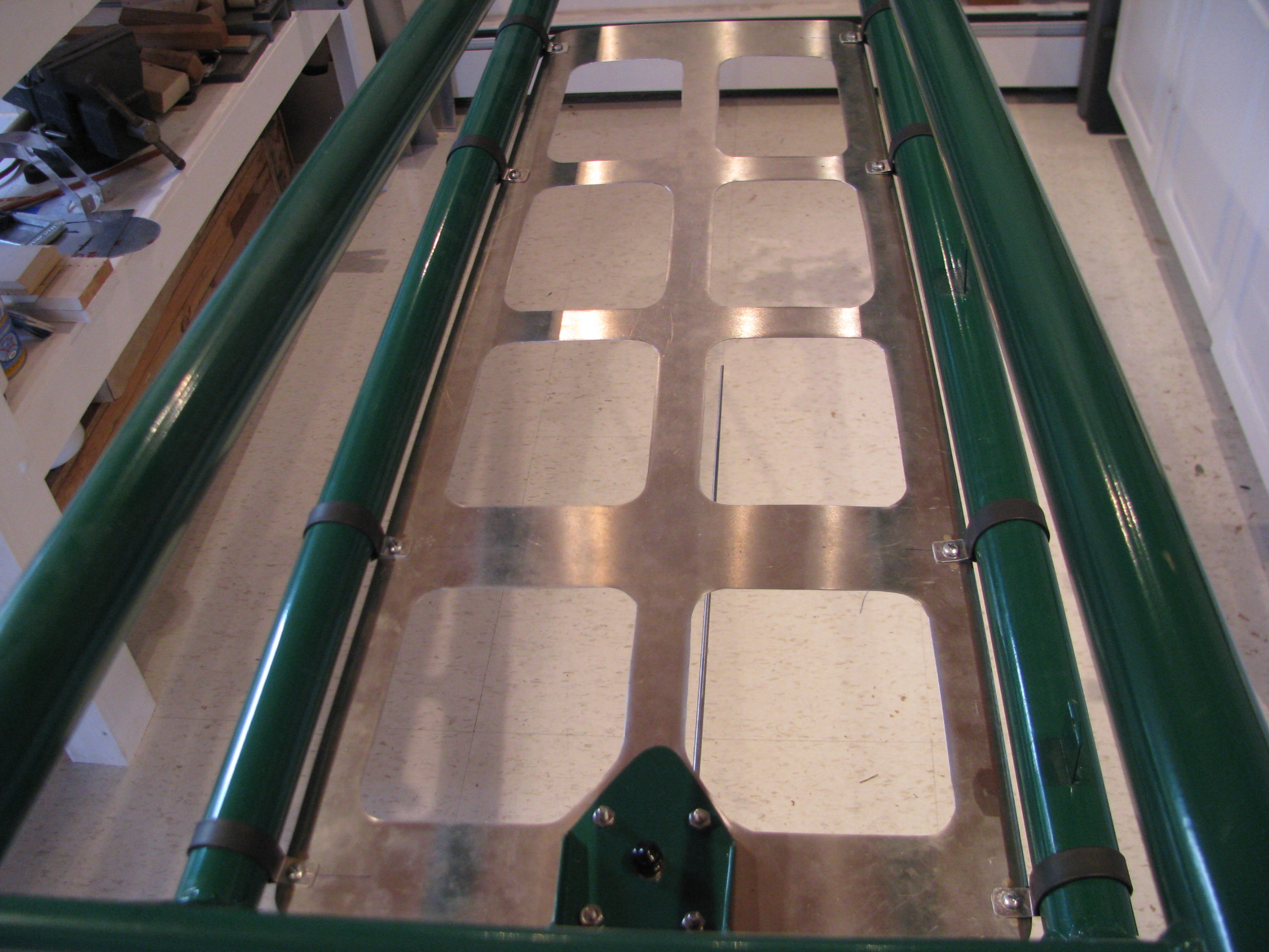
After having read Juan Rivera’s web site I decided that I would include a ground plane to improve the performance of the VHF communications antenna. The comm frequency range is 118 to 136 MHz. Therefore the 1/4 wavelength range is 21 to 25 inches. The sheet is 28 inches long. The longest diagonal opening is about 6.5 inches. No hole should be more than 1/10 wavelength (8.5 to 10 inches) so this should work well.
Cutting the sheet was a royal pain, but I didn’t want to just rivet strips together as the impedance across the joints would have adversely affected the RF performance of the ground plane. Drawing for the ground plane sheet is GroundPlane_B_072012.pdf.
Beacon Strobe
02/10/13 13:34 Filed in: All
Working my way forward, I knew I wanted a strobe of some form. Traditional commercial strobes are expensive, heavy, and generate several hundred volt spikes that have to be well contained or will play hell with your electronics and radio.
LED technology has made leaps and bounds in recents years. I decided to build my own strobes based on some new 900 Lumen CRE LEDs. That’s 900 lumens each. My old-fashioned living-room flood light bulbs are each 800 lumens at 90watts, just to put that in perspective. According to the spec sheet you can get almost twice that light per device if it is not continuous duty by overdriving the current.
So six of these LEDs with a peak of 1800 lumens each gets us about 10,000 lumens. The trick is handling the current. At 4amps per device that’s 24 amps. You certainly don’t want to switch that on and off directly from the battery. The current loop in the ship’s wiring would induce its own set of problems.
So to deal with that I developed a little circuit that charges up a capacitor bank, discharges through the LEDs then charges up again. The sequence is a 25millisecond flash, pause 100 milliseconds, another 25 millisecond flash, then pause 1.5 seconds, repeat forever. The caps charge during that 1.5second delay and therefore the average current to the whole strobe unit is 0.3A at 12V and should be very easy on the rest of the ship’s systems.
Best of all, the thing weighs next to nothing. I haven’t measured, but it can’t be more than a couple of ounces.
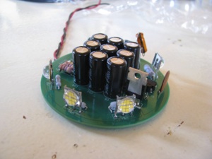
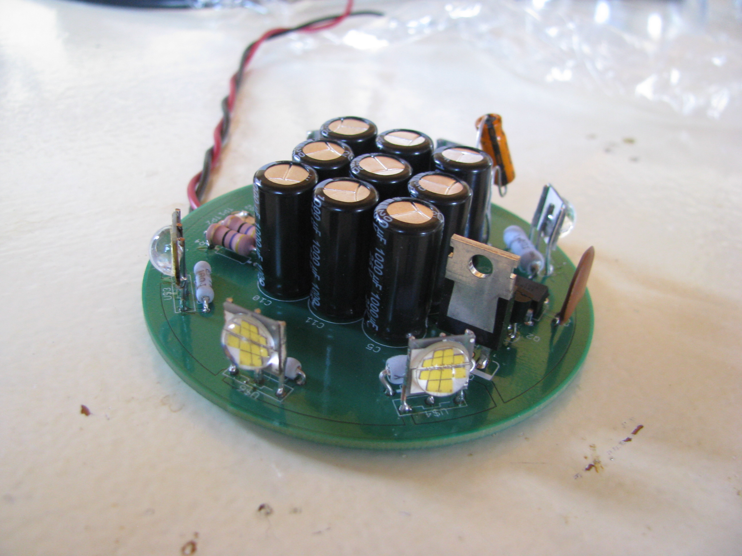
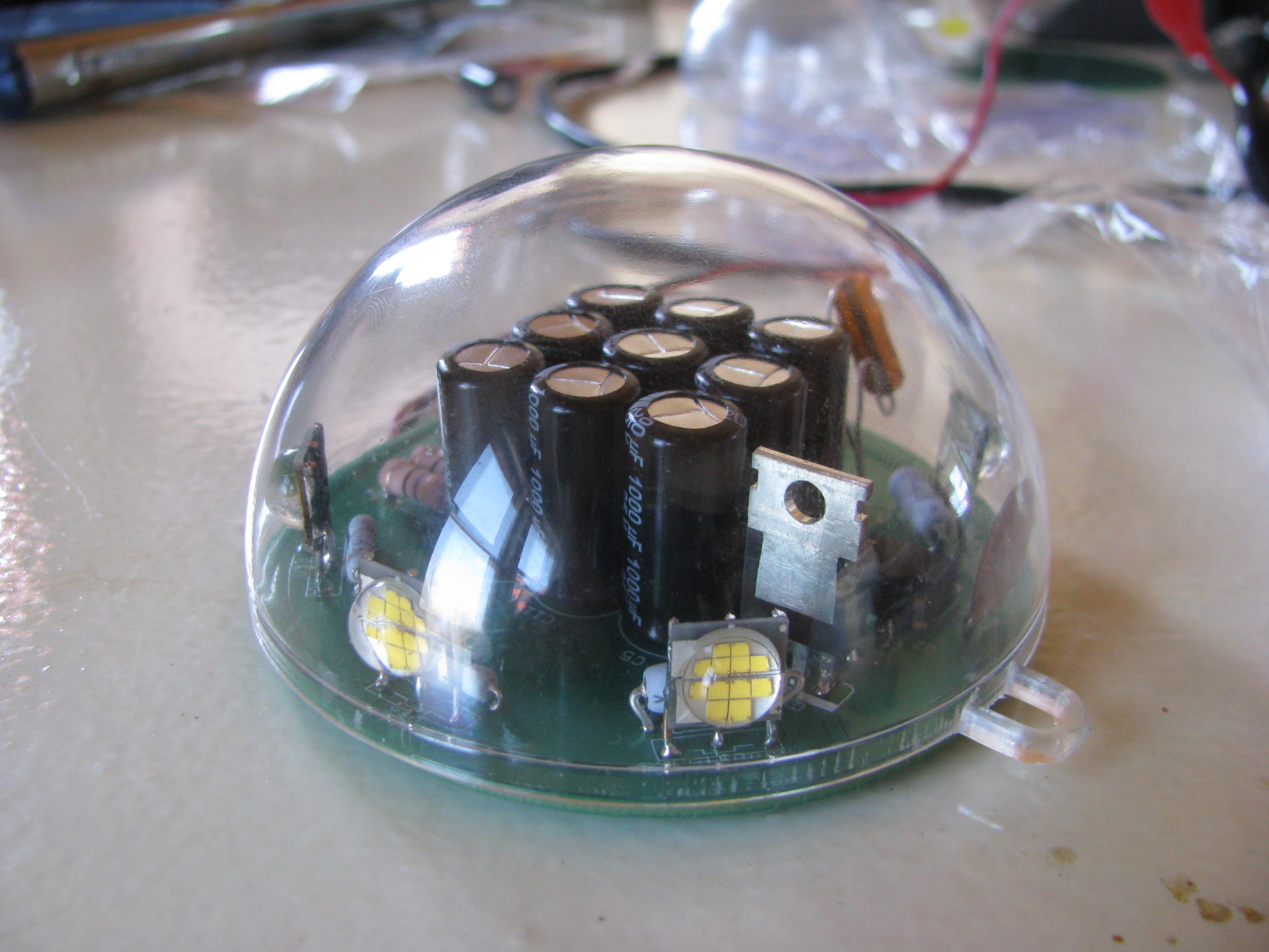
Here’s the circuit. Ignore the two capacitors dangling in the breeze. They are bulk and decoupling for the ATTiny85 microcontroller that controls the sequence. I forgot to order SMT caps from Digikey and will replace those before buttoning it up.
For those interested the schematic can be seen at Strobe_A.pdf. If you do something like this, pay attention to the ripple current rating of the capacitors. Layout is Strobe_A_top.pdf.

The PCB was sized to fit in a polycarbonate sphere bought at a craft store. The shell is designed to be used as a homemade christmas ornament.
I used Sunstone circuits “Value Proto” service for my PCB. This is a very cheap PCB fab process that uses unused panel space on other designs going through to keep your individual cost down. The down side is that the lead time can be long since they have to wait for a design with spare panel space - but hey, it’s very, very cheap.
If you do something like this, bear in mind that if the lights were left ON continuously (not blinking) it would heat up quickly and destroy itself. This circuit only works if the duty cycle (lights on period) is very, very low. I have left it running for days blinking along with no problems and cool to the touch, with flash pulses that are retina-melting. If you look at it directly by mistake you will see spots for an hour.
LED technology has made leaps and bounds in recents years. I decided to build my own strobes based on some new 900 Lumen CRE LEDs. That’s 900 lumens each. My old-fashioned living-room flood light bulbs are each 800 lumens at 90watts, just to put that in perspective. According to the spec sheet you can get almost twice that light per device if it is not continuous duty by overdriving the current.
So six of these LEDs with a peak of 1800 lumens each gets us about 10,000 lumens. The trick is handling the current. At 4amps per device that’s 24 amps. You certainly don’t want to switch that on and off directly from the battery. The current loop in the ship’s wiring would induce its own set of problems.
So to deal with that I developed a little circuit that charges up a capacitor bank, discharges through the LEDs then charges up again. The sequence is a 25millisecond flash, pause 100 milliseconds, another 25 millisecond flash, then pause 1.5 seconds, repeat forever. The caps charge during that 1.5second delay and therefore the average current to the whole strobe unit is 0.3A at 12V and should be very easy on the rest of the ship’s systems.
Best of all, the thing weighs next to nothing. I haven’t measured, but it can’t be more than a couple of ounces.
Here’s the circuit. Ignore the two capacitors dangling in the breeze. They are bulk and decoupling for the ATTiny85 microcontroller that controls the sequence. I forgot to order SMT caps from Digikey and will replace those before buttoning it up.
For those interested the schematic can be seen at Strobe_A.pdf. If you do something like this, pay attention to the ripple current rating of the capacitors. Layout is Strobe_A_top.pdf.
The PCB was sized to fit in a polycarbonate sphere bought at a craft store. The shell is designed to be used as a homemade christmas ornament.
I used Sunstone circuits “Value Proto” service for my PCB. This is a very cheap PCB fab process that uses unused panel space on other designs going through to keep your individual cost down. The down side is that the lead time can be long since they have to wait for a design with spare panel space - but hey, it’s very, very cheap.
If you do something like this, bear in mind that if the lights were left ON continuously (not blinking) it would heat up quickly and destroy itself. This circuit only works if the duty cycle (lights on period) is very, very low. I have left it running for days blinking along with no problems and cool to the touch, with flash pulses that are retina-melting. If you look at it directly by mistake you will see spots for an hour.