
Seatpan
Last SP Priming
10/28/14 12:38 Filed in: All
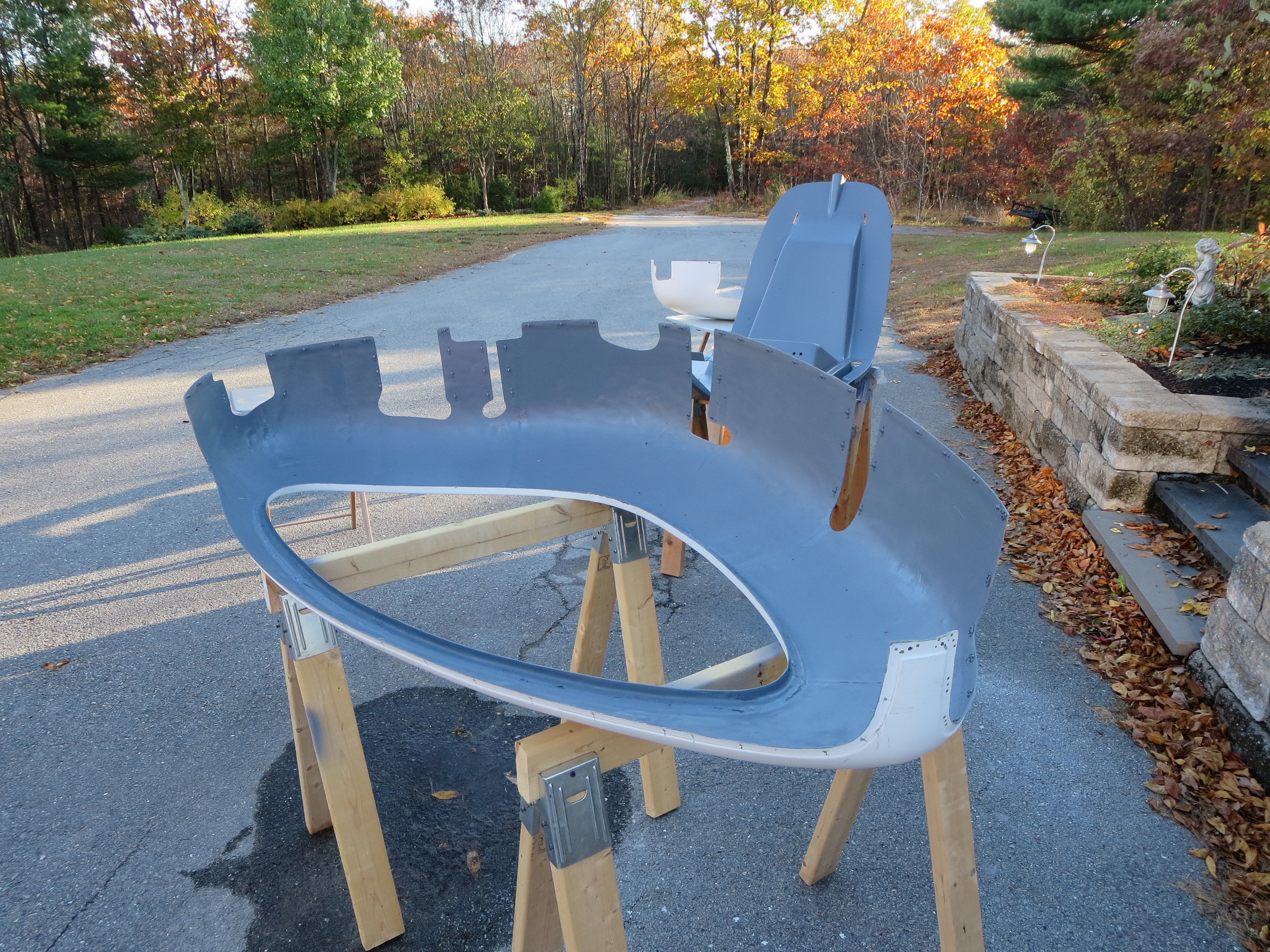
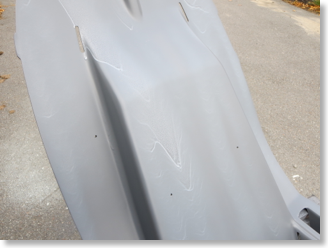
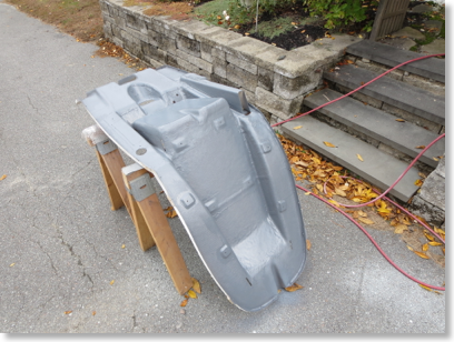
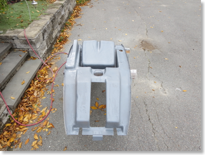
After the disastrous last priming session, I sanded down and removed most of the previous coat of primer. Then, more importantly, waited for relatively dry and mostly sunny conditions. Much, much, much better results.
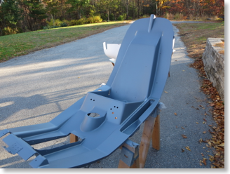
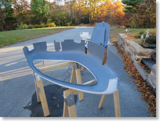
I also spent a whole lot more time tweaking the gun for a good spray pattern and quantity. This is kind of a matter of feel as much as anything else.
The interior of the cabin will be painted with a Rustoleum "Simply Stone" textured paint. It's kind of like spatter paint from old car trunks. The seat pan top and instrument pod will be satin black for low reflections.
More SP Priming
10/21/14 12:14 Filed in: All
Lulled into smugness over how easy the primer worked out on the back side of the seatpan, I filled and sanded the top side and primed it too as well as the panel.
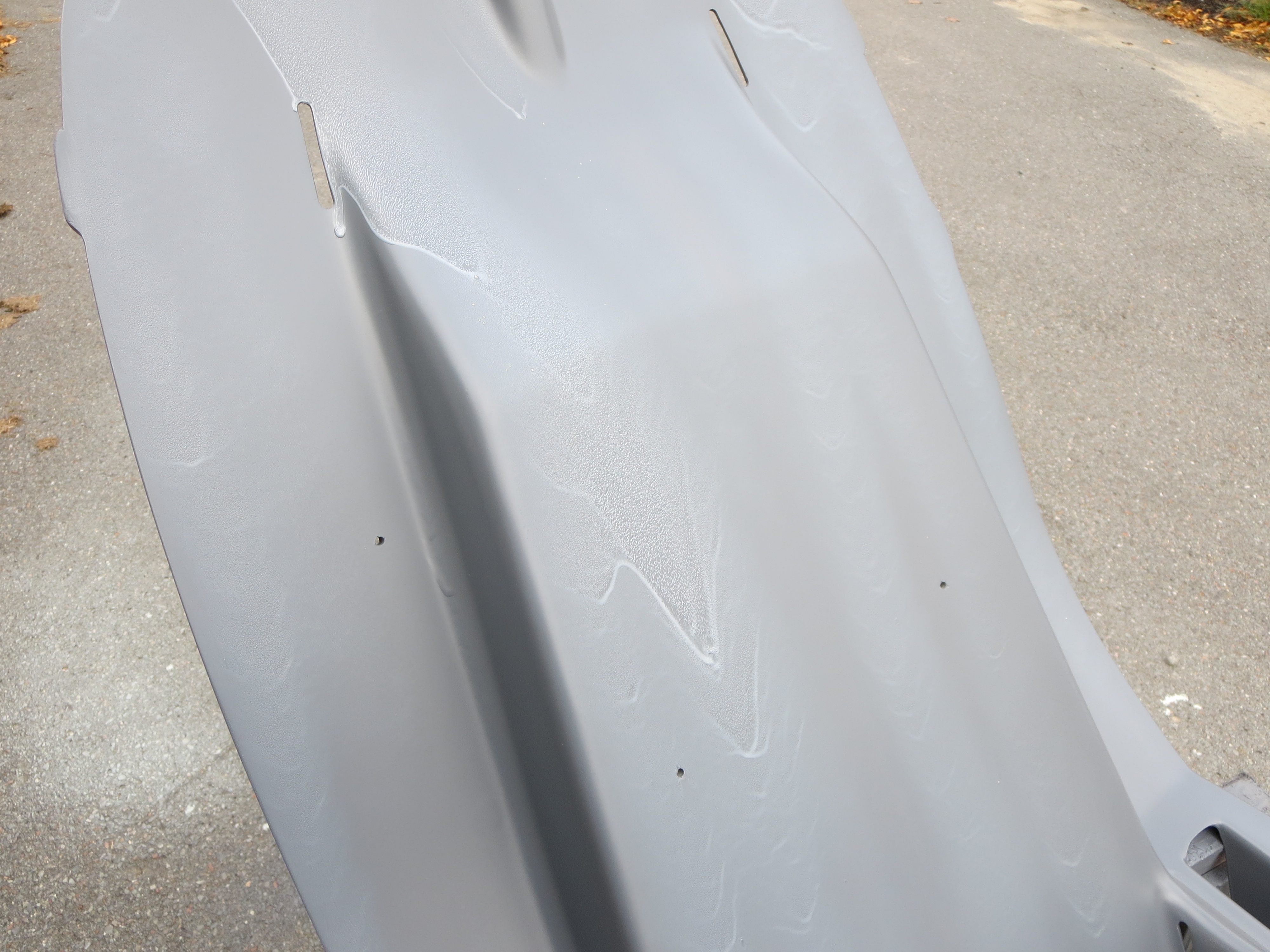
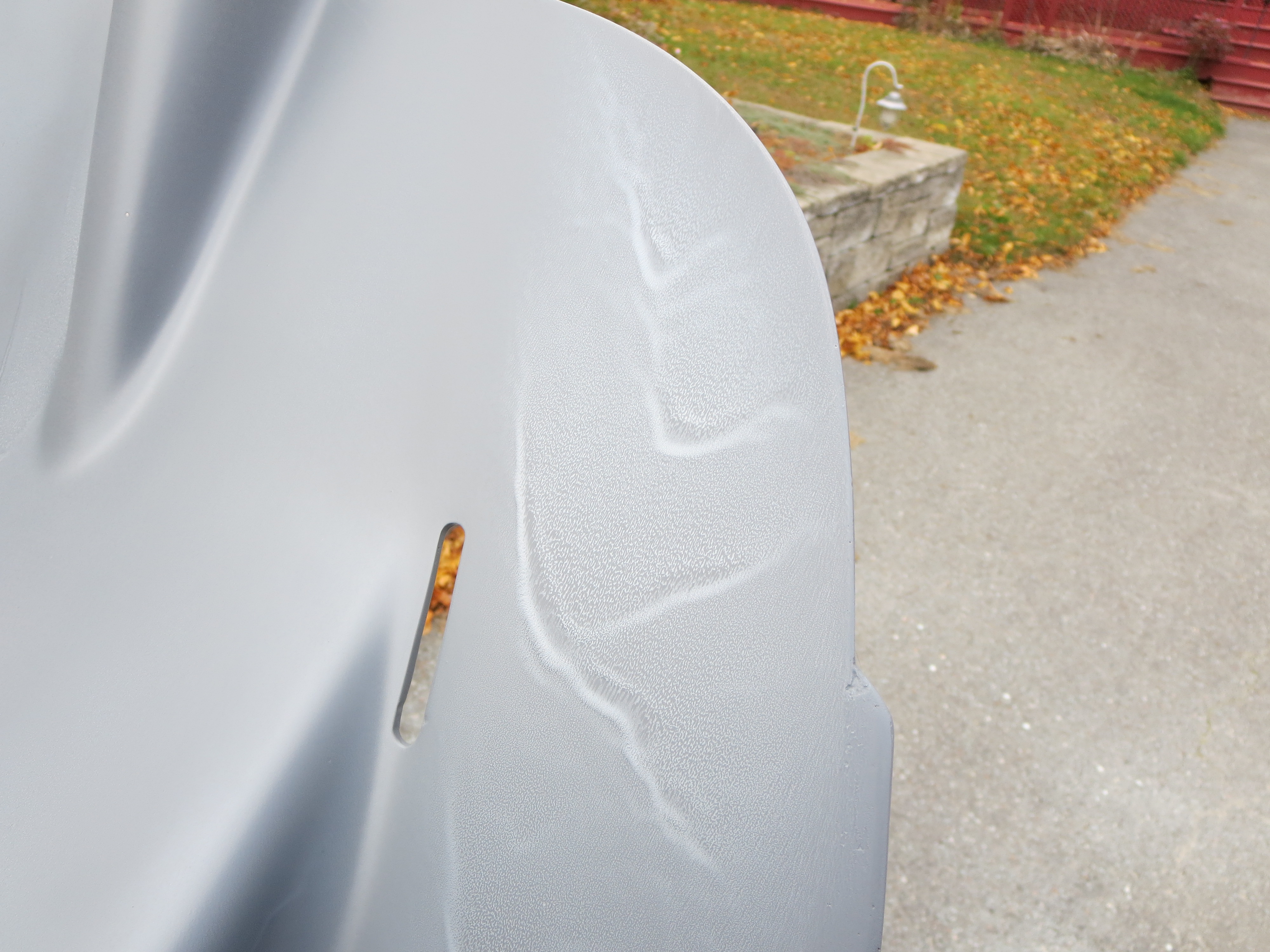
DISASTER. Right when I was thinking this painting stuff wasn't too hard, this thing turned into a runny, saggy, ugly mess.
Yuck! You can see the sags, runs, and droops.

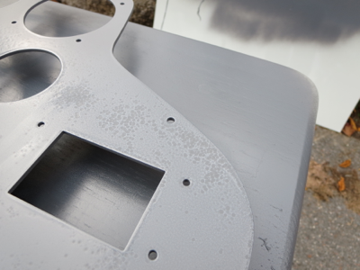
This is the cut panel blank which I primed as well. Those aren't really fisheyes. They are more dimples.
Very rough texture when dry.
Conclusion: Weather, weather, weather. Whereas when I primed the rear of the pan, the day was sunny and dry, the day I did the top side was cloudy and overcast and the humidity was relatively high. It was supposed to rain that afternoon and I wanted to get the primer on before it turned wet. Because of the moisture in the air and the lack of sun I think two things happened. 1) When I did my final wipedown with IPA, it never evaporated all the way. I think that is why the panel has the dimples. There was still residual IPA in the pores of the aluminum. 2) Because of the moisture and lack of sun, the primer did not dry or flash as quickly. The longer to stayed on wet, the more it sagged and ran.
This epoxy primer is tough stuff, so this will be laborious to sand off and start again, but that is the price to pay for getting too cocky about painting. At least it was the only primer. My lesson is learned and I will redouble my attention to conditions.
Lesson learned.
DISASTER. Right when I was thinking this painting stuff wasn't too hard, this thing turned into a runny, saggy, ugly mess.

Yuck! You can see the sags, runs, and droops.

This is the cut panel blank which I primed as well. Those aren't really fisheyes. They are more dimples.
Very rough texture when dry.
Conclusion: Weather, weather, weather. Whereas when I primed the rear of the pan, the day was sunny and dry, the day I did the top side was cloudy and overcast and the humidity was relatively high. It was supposed to rain that afternoon and I wanted to get the primer on before it turned wet. Because of the moisture in the air and the lack of sun I think two things happened. 1) When I did my final wipedown with IPA, it never evaporated all the way. I think that is why the panel has the dimples. There was still residual IPA in the pores of the aluminum. 2) Because of the moisture and lack of sun, the primer did not dry or flash as quickly. The longer to stayed on wet, the more it sagged and ran.
This epoxy primer is tough stuff, so this will be laborious to sand off and start again, but that is the price to pay for getting too cocky about painting. At least it was the only primer. My lesson is learned and I will redouble my attention to conditions.
Lesson learned.
Seat Pan Rear Priming
10/18/14 12:04 Filed in: All
Since winter is rapidly approaching it is time to get painting out of the way while the weather is not impossible.
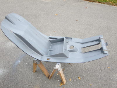
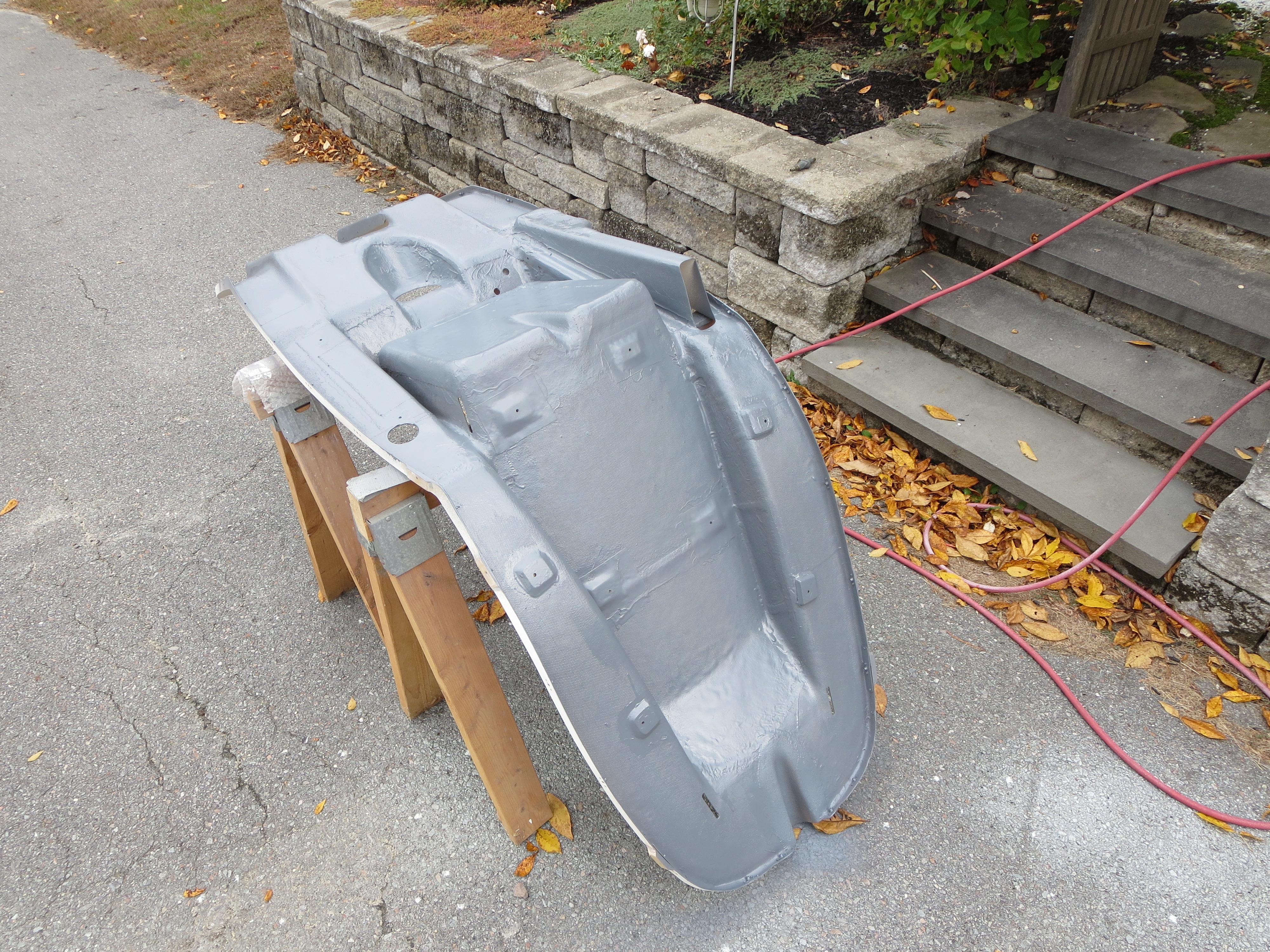
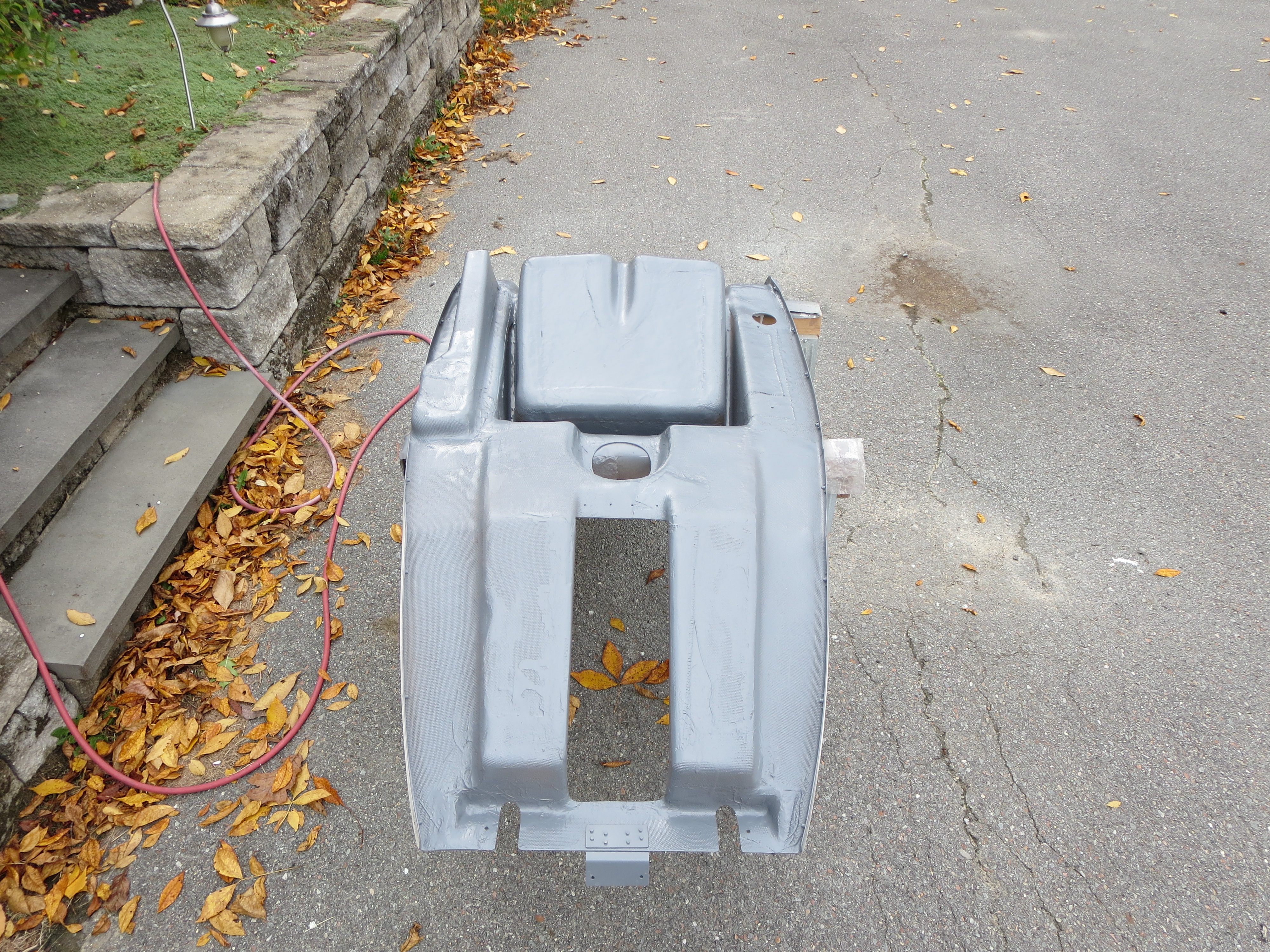
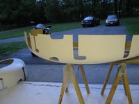
I broke out my Eastwood 2-part epoxy primer for a quick couple of coats to seal the rear of the pan. This stuff flows nicely and surprisingly almost exactly matches the color of the plastic used on the fuel tanks.
I am not too concerned about the finish on the backside of the pan. This is just a sealer, for the most part.
Instrument Pod Bracket
06/19/11 22:15 Filed in: All
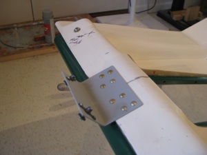
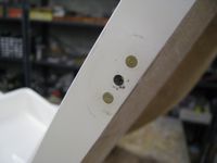
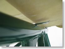
The front bracket is riveted on to stabilize the instrument pod. I have a lot of solid rivets in stock from my RV project and use them wherever possible instead of pop rivets.
Pan Drilling
06/15/11 22:06 Filed in: All
Finally got around to drilling the pan to the frame. It took a little more flox and some sanding to get things perfectly level and the tabs in place without much bending of the tabs (only a couple needed very minor tweaking).
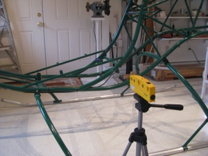
To drill the “blind” hole I first marked the arc at the correct distance, and also lined up a laser level with the hole from the outside. I started with a tiny bit and worked up to final, tweaking the position while checking from the inside.
It was only maybe 10 mils off by the time I got to final size. Not bad.
More BodyWork
05/23/11 22:01 Filed in: All
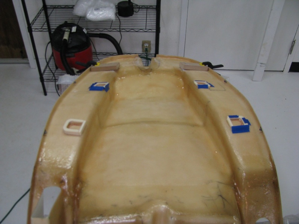
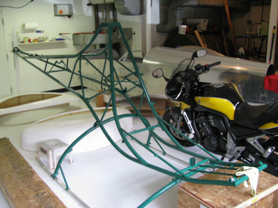
With the controls initially fit, it’s time to get back to mounting the seatpan and body shell. When I last left this task I had done all the fitting of the pan, and added some flox pads to fill the gaps between the pan and the metal tabs. They’re fit up pretty well and tomorrow I’ll drill the floorpan bolts.
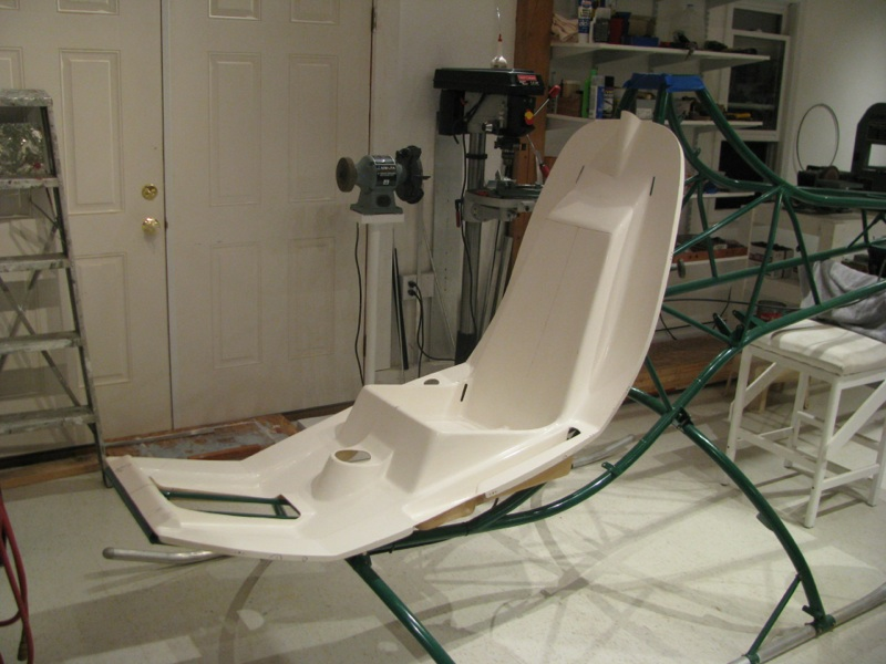
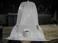
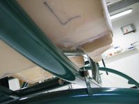
The pan pretty-well centered. The hump at the top is slightly offset to the right in this picture. This is because the mast will be slightly offset as well and the control rod presumably goes to the center of the mast.
Flox Pads
05/09/10 16:37 Filed in: All
I laid up a strip of fiberglass on the right hand side between the tabs. The pan currently rests on the tab welds, and I don't want to grind those or the flat part of the pan, so I will build up the area between the tabs slightly. Two strips of cloth was not enough, so I will probably build a little dam and pour a thin strip of flox (resin and cotton fibers) between the tab locations and sand it down until the pan rests on it.
I did this little section first to get reacquainted with fiberglass. It's been a while. Warm the resin! My can was maybe 65 degrees when I poured it and it glooped out like toothpaste. I had to heat the cup in a pan of warm water until it flowed like honey before starting. I remember that now and have re-set-up my box with a lightbulb to keep the resin warm on fiberglass days. Unlike most RV builders I actually like working with fiberglass. It's kinda magic to take chemicals and floppy cloth and build something remarkably strong out of it.
I made little U-shaped dams out of urethane foam to contain the flox "pads" for the seatpan mounting tabs. The foam was tacked down with 5-minute epoxy, then the flox was mixed and poured into the cavity. Flox is much thicker than resin, but still thin enough to flow, so you have to either pour it flat or contain it.
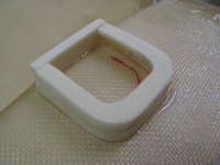
On the left side curve (second tab down from the top, the distance is quite large. Instead of bending the tab a ton, which will draw the hole closer to the curve of the seatback, I will just build this one up taller and leave the tab only slightly tweaked to be flat with it.
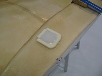
Flox poured. In all cases I built the pads to be taller than needed so I can then sand them down. The foam will then get sanded to a nice radius and a layer of thin cloth laid up over the top of the whole thing.
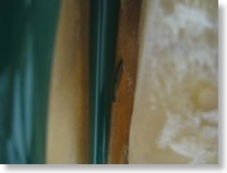
I cut the scribed slots in the fuselage halves. Overall the fiberglass looked sound, and there are just a couple of locations on the edges where the gelcoat got thick and there is a little separation between fiberglass layers. Those will get sanded out and a new strip of cloth or two added since they're right on the joggle lip mating surface and need to be strong. Gelcoat is non-structural. The interior is quite sloppy. There are a lot of little hairs and some places where resin pooled up. I will sand those down and probably be able to take down enough to compensate for the weight of my flox pads. Net sum zero on weight gain for my mods.
I may be critical of certain things on this kit that are less than perfect, but overall I am impressed by what you get for the money here. I have no idea how Eagle can do this for the price of the kit.
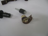
The sanding drums for the die grinder are quite remarkable. They work great, right up until you catch the end on a lip or edge, then they explode, sounding like a gunshot going off and just disappear at high speed across the room. I've used this thing a lot and have never done that before, then I had it happen twice in ten minutes. Guess that means I'm getting sloppy and it's time to stop for the day.
Eye, ear, and dust protection are a must.
More Pan Fitting
04/28/10 16:25 Filed in: All
I pulled the wood doubler out from between the collective pocket and the edge of the seat pan. I don't really know what it was supposed to do, but judging by how easily I was able to tear it out, not much. It was clearly glassed in as a secondary operation and an afterthought. If there is clearance after the seatpan is fit, I may glass in a layer just for peace of mind.
 You can see that the pan drops much further down on the left side now. So much so that instead of being canted to the right on the frame, it is now canted to the left. However, that single modification of removing that wooden piece allowed the seat pan to "nest-in" much better, and the clearance between the pan and the mounting tabs is now less than 1/4 inch all around. With my floxed pads and very, very minor bending, this will be a clean fit (my prediction).
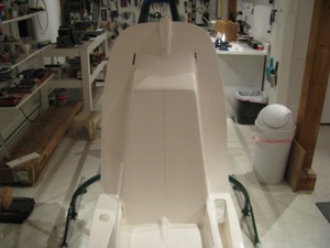
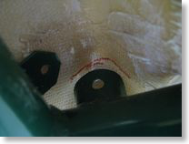
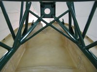 This view is looking up from the bottom at the back of the seat pan. You can see now that the seat is offset to the left. I am discovering the limitations of the "video" approach, instead of a manual and blueprints. I would very much like to know the exact offset of the control rod clearance tunnel at the top of the seat pan relative to the hood bracket at the top of the frame. You really have to watch BJ closely. As far as I can tell, he only mentions in one brief sentence, much later on, that the hump is intended to be aligned with the hole at the top of the frame, and the seat pan edges are centered relative to the frame tubes.
Of course with some prints and a manual this would all be immediately evident. Instead you have to watch the same video over and over (drives my daughter nuts) to try to glean this.
Perhaps I just got spoiled with the Van's RV8A kit, which has great documentation by comparison. Now don't get me wrong, I am immensely impressed with the Helicycle kit so far. For the money spent, the frame, fiberglass, materials, and especially the machined parts appear to be of very high quality. The budget was spent on machining parts and tooling, and not on documentation.
The source of the misalignment are the vertical tabs next to the collective pocket. Looks like those have to be bent inward a hair.
One thing I do not like about the fiberglass is the appearance of the bottom surface. The whitish areas almost appear as if they weren't wetted out fully. When I get my epoxy I will probably brush on a thin coat to "seal" them. It doesn't look to be a structural issue, but certainly a cosmetic one that bothers me.
I looked ahead in the videos to the next step, which is the instrument pod mounting. I did not get the 12 inch long 3/8" drill bit when I picked up the kit, so I'll probably have to order one. I must admit that the "jiggle and elongate the holes" approach does not excite me. I'm pretty sure there must be some sort of clamping arrangement that can be constructed to more precisely achieve the same effect. I don't like the idea of elongating the holes, then tightening the bolts to hold it all in place. Once again, I will consult Tim Drnec's and Juan R's sites to see what they did. Those two guys really set a high bar when it comes to fastidiousness and quality workmanship. While I want a straight, true, clean, and reliable ship, I doubt that I will be able to meet their standards of excellence.
Pan Fitting
04/24/10 21:35 Filed in: All
Fitting seat pan. Cleaned up holes and edges. Mounted nutplates (with flush rivets, instead of the pop rivets), and started trying to fit the pan to the frame. The fit is tricky. A lot more material than I would have thought had to be removed from the outsides of the front of the footwells. Lots of small trimming, then refitting of the pan.
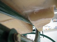
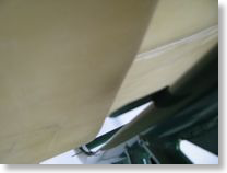
As can be seen below, a fair amount of material has to come off both sides of the front of the footwells to fit down between the two front frame tubes. The fiberglass is at least doubled up here around the bends, so hopefully the strength is not compromised too much. We shall see as this will probably be a high stress area in getting in and out of the ship.
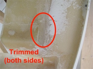
As can be seen below, a fair amount of material has to come off both sides of the front of the footwells to fit down between the two front frame tubes. The fiberglass is at least doubled up here around the bends, so hopefully the strength is not compromised too much. We shall see as this will probably be a high stress area in getting in and out of the ship.
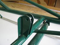
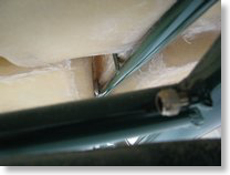
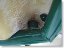
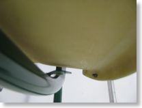
Shown here is the grinding I had to do on the control bracket to clear the seat pan as specified in the video. Still seems to be plenty of meat between the hole and the ground edge. There's about 1/16 of an inch clearance between it and the seat pan. I DO plan on repainting the frame after all the preliminaries are done just prior to final assembly. Green - what was he thinking?
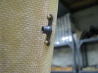
Here are the control tube mount tab locations when the front of the pan is flush against the mounting tabs. Pretty tight. I am going to shave a little off the inside of the round to fit the front plane of the pan down a hair lower.
 Aft of the front two holes, the fit is not good. There is a large gap between the floor pan and the seat back. I am not sure I want to, or even could, bend the tabs enough to close the gap. Also, the seat pan is canted to the right. The right cant seems to be partially due to the frame first hitting the wooden reinforcing rod that is laminated alongside the collective pocket. I noticed on Tim Drnec's site that he just removed this piece, and I may do so too. It is kind of sloppily glassed in there. Tim glassed in anchor nuts to the rear of the seat back for a nice flush, no penetration, mount of the pan. Though I doubt I will go to that extreme, I do think I will build up the areas immediately underneath the mounting tabs with flox and resin to bulk up the mounting points. Though it's more work, I think it will beef up the fiberglass under the mounting points, which seemed a little weak with just a hole through that thin layer of fiberglass.
 I placed my first order to Aircraft Spruce for this project to get some fresh epoxy and flox for this procedure. Prior to executing this mod I also need to better jig the seat pan to the frame, especially in the rear before drilling any holes. There is quite a bit of side-side flex on the pan and I want to get it leveled and centered perfectly since the cabin mounts to the pan and presumably any errors will be magnified from that point onward. Perhaps I am seeming overly anal about this, but I want to be as precise as possible since this is a sophisticated and complex mechanical beast. In airplane construction there appears to be a little more wiggle room. Not so with helicopters. Precision matters.
As can be seen below, a fair amount of material has to come off both sides of the front of the footwells to fit down between the two front frame tubes. The fiberglass is at least doubled up here around the bends, so hopefully the strength is not compromised too much. We shall see as this will probably be a high stress area in getting in and out of the ship.
As can be seen below, a fair amount of material has to come off both sides of the front of the footwells to fit down between the two front frame tubes. The fiberglass is at least doubled up here around the bends, so hopefully the strength is not compromised too much. We shall see as this will probably be a high stress area in getting in and out of the ship.
Shown here is the grinding I had to do on the control bracket to clear the seat pan as specified in the video. Still seems to be plenty of meat between the hole and the ground edge. There's about 1/16 of an inch clearance between it and the seat pan. I DO plan on repainting the frame after all the preliminaries are done just prior to final assembly. Green - what was he thinking?
Here are the control tube mount tab locations when the front of the pan is flush against the mounting tabs. Pretty tight. I am going to shave a little off the inside of the round to fit the front plane of the pan down a hair lower.